
Related Manuals for Northern Lights PX-300K1 Series A.C. Generator


Summary of Contents for Northern Lights PX-300K1 Series A.C. Generator
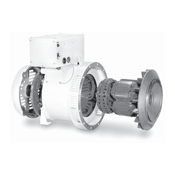
- Page 1 PERATOR’S PERATOR’S & ARTS & ARTS ANUAL ANUAL PX-300K1 SERIES A.C. GENERATORS For Generator Models: PX- 308 K 1 , PX309K1, PX- 310 K 1 , PX- 312 K 1 , PX- 316 K 1 , PX- 320 K 1, PX-325K1, and PX-332K1...
- Page 2 4420 14th Avenue N.W. Seattle, WA 98107 Tel: (206) 789-3880 Fax: (206) 782-5455 Copyright ©2009 Northern Lights, Inc. All rights reserved. Northern Lights™, and the Northern Lights logo are trademarks of Northern Lights, Inc. Printed in U.S.A. PART NO.: OPX300K1 09/09...
-
Page 3: Table Of Contents
This publication is the property of Northern Lights, Inc. It may not be reproduced in whole or in part without the written permission of Northern Lights, Inc. © Northern Lights, Inc. 2009. All rights reserved. Litho U.S.A. Publication number OPX300K1 09/09... -
Page 4: Introduction
Introduction • Insulation Resistance and Dielectric: When This manual describes procedures for operation, measuring insulation resistance and dielectric, be maintenance, inspection and adjustment. It will help the sure to disconnect the AVR and rectifi er. operator realize peak performance through effective, economical and safe operation. -
Page 5: Models And Serial Numbers
M864 ..............PX-325K M984 ............PX-332K1 SERIAL NUMBERS • When referencing Northern Lights equip ment by serial number, it is important to differentiate between the engine, generator end and generator set serial numbers. • The engine serial number is either on a metal tag or stamped directly into the engine block. -
Page 6: Mechanical Construction
Mechanical Construction STATOR COUPLING BOLT SPECIFICATIONS The stator frame is fabricated from rolled steel. The The Coupling Bolt Torque for all PX-300K series models round construction provides rigidity and strength to is 32 lbs.ft. resist excessive mechanical shocks. The stator core is made of high quality silicon steel plates coated with COUPLING WITH PRIME MOVER insulating fi... -
Page 7: Performance And Function Excitation System
Performance and Function EXCITATION SYSTEM The excitation system of the PX-300K Series genera- tor uses an Automatic Voltage Regulator (AVR) which uses a portion of the output power to supply controlled DC power to the exciter fi eld (EX) as show in Figure 2. When DC power is supplied to the exciter fi... -
Page 8: Characteristics
Characteristics VOLTAGE REGULATION SHORT CIRCUIT Generator terminal voltage regulation is within ± 1% of the PX-300K Series AC generators can provide over 300% of rated voltage in lagging power factor. 1.0 to 0.8, when the the rated current for a short period of time, with an load is varied gradually from no load to full load. -
Page 9: Operation - Generator Set
Operation – Generator Set STOPPING After putting the running generator in a no-load condition STARTING by removing the generator load, stop the engine in Before starting generator, check the following: accordance with the Engine Manual. 1. Make sure that the wiring is correct. 2. -
Page 10: Operation - Voltage Regulator
Operation – Automatic Voltage Regulator SAFETY RULES • Do not leave AVR connected when testing generator 2. Voltage Adjustment: with high-pot or megger. If the voltage output is low, increase the voltage by • Adjust the engine only when the CPR is in “OFF” turning the Voltage Adjust (VR1) slowly clockwise. -
Page 11: Maintenance
Maintenance BEARING INSPECTION b. Using a bearing puller, extract bearing from For bearing inspection, make sure that there is no shaft. abnormal sound during normal running and no c. When installing a new bearing, place a steel pipe over heating. Greasing is not necessary for generators on the inner race surface, and fi... -
Page 12: Parts Replacement Method
Maintenance 2. Replacement of Rotary Rectifi er Parts: • Good surge absorber elements have about 10-30 K a. Rotary rectifi er parts are all located at the rear ohms, but if the resistance reading is near 0 ohms, the of Exciter rotor. For parts replacement, remove the surge absorber elements is defective and must be bearing shield. -
Page 13: Automatic Voltage Regulator Maintenance
4. Rotating Rectifi er Assembly Detailed Structure: Figure 9. Rotating Rectifi er. Maintenance – Automatic Voltage Regulator 1. Keep the AVR clean at all times. Make sure no dust or moisture accumulates on the AVR. 2. Inspect periodically making sure that wiring connections are not loose. OPX300K1 09/09... -
Page 14: Generator Specifi Cations
Generator Specifi cations: Taiyo Winding Resistances All ratings in Ohms @ 20° C Model 4 Wire - 1 Phase 12 Wire - 3 Phase Number –V –V MAIN PX-308K1 0.3685 ohms 0.3685 ohms 0.599 ohms STATOR: PX-309K1 0.3685 ohms 0.3685 ohms PX-310K1 0.2480 ohms 0.2480 ohms... -
Page 15: Generator Specifi Cations
Generator Specifi cations: Taiyo Winding Resistances All ratings in Ohms @ 20° C Model Number U - V EXCITER PX-308K1 & PX-309K1 0.493 ohms ROTOR: PX-310K1 0.493 ohms PX-312K1 0.493 ohms PX-316K1 0.527 ohms PX-320K1 0.532 ohms PX-325K1 0.573 ohms PX-332K1 0.311 ohms Model Number... -
Page 16: Specifi Cations: Dst-51-Dfk
Automatic Voltage Regulator: DST-51-DFK Sensing Output Frequency 50 Hz 60 Hz (4) – (100) 100V Class 100 Volt Class 100V 120V (4) – (200) 200V Class 200 Volt Class 200V 240V Phase: Single Phase Single Phase Power Input Voltage: 100V 139V (4 –... -
Page 17: Troubleshooting
Trouble Shooting PROBLEM POSSIBLE CAUSE RECOMMENDATION(S) Only a FEW VOLTS Loss of residual magnetism of the exiter fi eld • Flash fi eld. of output Disconnection or short circuit of windings • Check the insulation of all windings and check the resistance value. Defective AVR •... -
Page 18: Parts List
PX-300K1 Series Parts List No Description PX-308K1/PX309K1 PX-310K1 PX-312K1 PX-316K1 PX-320K1 Stator Assembly WKC-00011-ST WKC-00012-ST WKC-00013-ST WKC-00014-ST WKC-00015-ST (1-Phase) Stator Assembly WKC-00016-ST WKC-00017-ST WKC-00018-ST WKC-00019-ST WKC-00020-ST (3-Phase) Rotor Assembly WKC-00011-RT WKC-00012-RT WKC-00013-RT WKC-00014-RT WKC-00015-RT Excitor Stator Assembly WKC-00031-ST WKC-00031-ST WKC-00031-ST WKC-00032-ST WKC-00032-ST (1-Phase) - Page 19 PX-300K1 Series Parts List No Description PX-308K1/PX-309K1 PX-310K1 PX-312K1 PX-316K1 PX-320K1 Generator Mounting Bracket 3T301-267-2 R 3T301-268-2 R 3T301-268-2 R 3T301-269-2 R 3T301-269-2 R 3T301-267-2 L 3T301-268-2 L 3T301-268-2 L 3T301-269-2 L 3T301-269-2 L J-Box Support Bracket, Right 4T301-309 3T301-309 3T301-309 3T301-309 3T301-309...
- Page 20 PX-320C Parts List Description PX-320C Stator Assembly WKC-00020-1-ST Rotor Assembly WKC-00020-1-RT Excitor Stator Assembly WKC-00034-ST Rectifi er Assembly 3T201-084 Bearing Shield 3T301-253-3 O-Ring 1BG70 Ball Bearing 6306ZZ Ventilation Cover 3T302-896 Terminal Box 3T302-637-1 (M Type) Terminal Box 4T301-108 (Top) Terminal Box 4T301-109 (Side) Rubber Damper...
- Page 21 Notes OPX300K1 09/09...
- Page 22 PX-325K1 Parts List Single Phase Description PX-325K1 1 Phase Stator Assembly WKC-00077-ST (1-Phase) Rotor Assembly WKC-00077-RT Excitor Stator Assembly WKC-00032-ST (1-Phase) Rectifi er Assembly 3T201-084 Bearing Shield 3T301-253-3 O-Ring 1BG70 Ball Bearing 6306ZZ Ventilation Cover 3T301-331 Terminal Box 3T301-168-2 Terminal Box 4T301-108 (Top) Terminal Box...
- Page 23 PX-325K1 Parts List Three Phase Description PX-325K 3 Phase Stator Assembly WKC-00078-ST (1-Phase) Rotor Assembly WKC-00078-RT Excitor Stator Assembly WKC-00034-ST (1-Phase) Rectifi er Assembly 3T201-084 Bearing Shield 3T301-253-3 O-Ring 1BG70 Ball Bearing 6306ZZ Ventilation Cover 3T301-331 Terminal Box 3T302-637 Terminal Box 4T302-144 (Top) Terminal Box...
- Page 24 PX-332K1 Parts List With Small Junction Box Description Part Number Stator Assembly (Single Phase) WKC-00039-ST Stator Assembly (Three Phase) WKC-00040-ST Rotor Assembly WKC-00039-RT Exciter Stator Assembly (Single Phase) WKC-00060-ST Exciter Stator Assembly (Three Phase) WKC-00061-ST Rectifi er Assembly 3T201-084 Bearing Shield 3T301-349-2 O-Ring 1BG90...
- Page 25 PX-332K1 Parts List Small Junction Box Description Part Number •• Junction Box Sub-assembly 4T301-496-2 (includes keys 9 - 11) Junction Box 3T301-222-2 Junction Box, Top 4T301-108 Junction Box, Side 4T301-109 22-42037 Circuit Breaker (for AVR) 22-42053 Circuit Breaker (for Engine) 22-42043 Terminal (for AVR) TS-212-6P...
- Page 26 PX-332K1 Parts List With Large Junction Box Description Part Number Stator Assembly (Single Phase) WKC-00039-ST Stator Assembly (Three Phase) WKC-00040-ST Rotor Assembly WKC-00039-RT Exciter Stator Assembly (Single Phase) WKC-00060-ST Exciter Stator Assembly (Three Phase) WKC-00061-ST Rectifi er Assembly 3T201-084 Bearing Shield 3T301-349-2 O-Ring 1BG90...
- Page 27 PX-332K1 Parts List Large Junction Box Rigid Mounting Description Part Number •• Junction Box Assembly 39-65417 Junction Box 3T302-142 Junction Box, Top 4T302-144 Junction Box, Side 4T302-145 Terminal (Output) 22-45413 AVR (Automatic Voltage Reg.) 22-42037 Circuit Breaker (for AVR) 22-42053 Circuit Breaker (for Engine) 22-42043 Terminal (for AVR)
- Page 28 PX-332K1 Parts List 1 Phase Junction Box On Flex Mounts Description Part Number •• Junction Box Assembly 39-65418 Junction Box 3T302-858-1 Junction Box, Top 4T302-144 Junction Box, Side 4T302-859 Terminal (Output) TE-K60-4 AVR (Automatic Voltage Reg.) 22-42037 Circuit Breaker (for AVR) 22-42053 Circuit Breaker (for Engine) 22-42043...
-
Page 29: Parts List
PX-332K1 Parts List 3 Phase Junction Box On Flex Mounts Description Part Number •• Junction Box Assembly 39-65419 (Includes keys 9-11, 18, 25) Junction Box 3T302-784-2 Junction Box, Top 4T302-144 Junction Box, Side 4T302-859 Terminal (Output) TE-K60-4 AVR (Automatic Voltage Reg.) 22-42037 Circuit Breaker (for AVR) 22-42053... -
Page 30: Wiring Diagram Avr Dst-51-Dfk
OPX300K1 09/09... - Page 31 4420 14th Ave. NW., Seattle WA 98107 Tel: (206) 789-3880 • 1-800-762-0165 • Fax: (206) 782-5455 Northern Lights and Lugger are registered trademarks of Northern Lights, Inc. www.northern-lights.com © 2009 All rights reserved. Litho USA.
Need help?
Do you have a question about the PX-300K1 Series A.C. Generator and is the answer not in the manual?
Questions and answers