
Subscribe to Our Youtube Channel
Related Manuals for Northern Lights NL673L


Summary of Contents for Northern Lights NL673L
- Page 1 ONL673L For Model: NL673L OPERATOR’S MANUAL Marine Generators | Marine Diesel Engines | Land-Based Generators...
- Page 2 fi ll port for diesel driven equipment. This label is to state: ULTRA LOW SULFUR FUEL ONLY Northern Lights is providing this label for application to the fuel inlet of the fuel supply tank for each engine or generator set. This is to be applied by the installer of the engine or gen set, or by the manufacturer of the equipment that the engine or gen set is installed in.
-
Page 3: Table Of Contents
This publication is the property of Northern Lights, Inc. It may not be reproduced in whole or in part without the written permission of Northern Lights, Inc. © Northern Lights, Inc. All rights reserved. Litho U.S.A. Publication number ONL673L 7/13... -
Page 4: Introduction
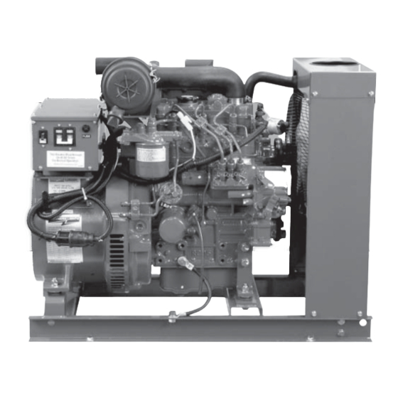
NL - Northern Lights industrial generator set Bore Cylinders 67 mm Northern Lights industrial diesel generator set with an 673 engine, TF-276D generator end, NL673L an automatic voltage regulator, and a radiator. Serial Numbers Your set has three serial numbers:... -
Page 5: Warranty
For replacement signs, ALWAYS STOP ENGINE proper placement of safety signs or clarifi cation on any BEFORE FUELING safety issue, consult your Northern Lights dealer or the MACHINE. Always fi ll factory. portable fuel tank outdoors. - Page 6 Revised 6-19-12 Safety Rules Prevent accidental discharge of starting fl uids by Operating equipment requires the full attention of storing all cans in a cool, safe place, away from sparks the operator. Do not use radio or music headphones or open fl ame. Store with cap securely on container. while operating machinery.
- Page 7 Among the potentially hazardous with a metal object. Use a volt-meter or hydrometer. chemicals that may be used with Northern Lights Frozen batteries may explode if charged. Never products are lubricants, charge a battery that has not been allowed to warm to at least 16 o C (60 o F).
- Page 8 Slowly loosen cap to relieve pressure before opening fully. Contact your Northern Lights dealer or Northern Lights factory for MSDS’s used on Northern Lights products. Avoid High Pressure Fluids Work in Well Ventilated Areas Relieve pressure prior to disconnecting pressurized lines.
-
Page 9: Safety Rules
Disposing of waste improperly can threaten the handling components containing environment and lead to unsafe working conditions. asbestos fi bers, including some Potentially harmful waste used in Northern Lights gaskets. equipment can include oil, fuel, coolant, fi lters and batteries. -
Page 10: Lock Out / Tag Out Procedures
Scope During maintenance, repairs or retooling of a Northern Lights generator set, simply turning the machine off or unplugging it while it is being worked on does not give enough protection to others who are not performing the maintenance or repair. - Page 11 Notes ONL673L 7/13...
-
Page 12: Component Locations Nl673 Industrial Generator
Industrial Generator Component Locations Figure 4: NL673L Non-Service Side. Figure 5: NL673L Service Side. 1. DC Alternator 7. Air Filter 19. Fuel Inlet and Return 13. Fuel Lift Pump 2. Muffl er, Exhaust Outlet 8. DC Circuit Breaker 14. Block Water Drain 20. -
Page 13: Northern Lights Generator Sets
Control Panels 1. SHUTDOWN BYPASS-PREHEAT SWITCH There are two functions built into this switch: preheating the engine and bypassing the engine safety shutdown circuit, enabling a start. Hold the switch in the ON position for approximately 10 to 20 seconds before starting a cold engine. - Page 14 Industrial Control Panels 1. ENGINE CONTROL SWITCH Manual Start (S-7.1 through S-7.6) Move the switch in the MANUAL position and the engine will start and run. Auto Start Panels (S-7.1 through S-7.6) When the switch is placed in the AUTO START position, the unit will automatically start if an ATS is connected.
-
Page 15: Operating Procedures
Operating Procedures BREAK-IN PERIOD STARTING FOR S-1, S-1B, S3, AND S4 SEE PAGE 6 FOR S7 1. The fi rst 100 hours on a new or reconditioned engine are critical to its life and performance. 1. Hold the Shutdown Bypass-Preheat switch in the ON 2. -
Page 16: Shutdowns And Alarms
SPARE PARTS 1. Your unit may be fi tted with a warning horn to 1. Northern Lights recommends that you keep the protect it from high water temperature or low oil following spare parts on hand for fi eld service. The pressure. -
Page 17: Servicing Schedule Chart
Servicing Schedule Chart The Servicing Schedule Chart below shows the service schedule required for proper maintenance of your generator set. More detailed coverage of each Service Point (SP) is listed on the page noted in the ‘page’ column. DAILY: EVERY 500 HOURS: Check oil level in engine Change primary fuel fi... - Page 18 Service Record Notes ONL673L 7/13...
-
Page 19: Servicing
Servicing LUBRICATION - GENERAL SP2. OIL CHANGES 1. Use only clean, high quality lubricants stored in 1. The set is delivered with special break-in oil. clean containers in a protected area. Change the engine oil and oil fi lter after 50 hours 2. -
Page 20: Air Filter
4. Replace with new element once every year. Part SP6. VALVE CLEARANCES number is: NL673L – #408620002 1. Readjust valve clearance after fi rst 50 hours of 5. After cleaning, shine a light from the element if operation and every 1000 hours thereafter. -
Page 21: Fuels - General
Avoid storing fuel for long periods of time. c. Fill the fuel tank at the end of each day’s operation. This will reduce condensation. Found on older NL673 units Found on newer NL673 & NL673L units ONL673L 7/13... -
Page 22: Bleeding The Fuel System
Serious infection or reaction can develop if proper medical treatment isn't adminis- tered immediately. Figure 11-B: NL673L Fuel System. 1. The fuel system is self-bleeding. However, any system may need manual bleeding when: a. A new fuel fi lter is installed;... - Page 23 Servicing Figure 12: Remove delivery line fl are nuts. Figure 16: Remove return line. Figure 13: Remove delivery lines. Figure 17: Unscrew injector. Figure 14: Cover lines, inlets and injection pump outlets. Figure 18: Remove and replace copper sealing washer. Figure 15: Remove return line nuts.
-
Page 24: Injector Service
1. Injectors should be checked every 1000 hours. 1. Since operating conditions may vary considerably, it Check should be made by a Northern Lights dealer is diffi cult to give a defi nite interval for checking the or local injection repair station. -
Page 25: Cooling System Flushing
Servicing SP14. COOLING SYSTEM FLUSHING ELECTRICAL SYSTEM - GENERAL 1. Flush the cooling system every 2500 hours or every 1. Never switch battery switch off or break the circuit 12 months, whichever comes fi rst. between the alternator and batteries while the engine is running. -
Page 26: Glow Plugs
Servicing GLOW PLUGS SP 18-19. BATTERY CARE 1. Each cylinder is supplied with a glow plug which 1. Check electrolyte level every 50 hours or once per serves to heat the combustion chamber for starting. month. Add distilled water to manufacturer’s recom- 2. -
Page 27: Ac Generator - Tf-276D
Revised 6-19-12 AC Generator - TF-276D GENERAL A Generator Set includes the engine, the generator, and the control or “J” box ( Figure 22 2. The generator and the control or “J” box produce the electrical power. 3. Generator excitation is provided by residual magnetism and electrical output voltage is controlled by the automatic voltage regulator (AVR) located in the control box (... -
Page 28: Connections
AC Generator - TF-276D CONNECTIONS 1. 120 Volt Output: a. 120 volt output can be selected by connecting the terminals of the control terminal board to 120 Figure 25 also see page 29 Figure 28: Output Terminal Board, 240 Volt Output 3. -
Page 29: Operation
Dust and foreign material may reduce the fl ow of d. Generator bearing should be replaced by your cooling air, reducing heat dissipation and causing Northern Lights dealer at 10,000 hours. the generator to overheat. 6. Check the brushes b. - Page 30 AC Generator - TF-276D 7. Replacing Brushes a. Shut down the generator. Remove four screws and end cover of the generator. b. Brush assembly is white plastic with two wires leading to it. It is located at ten o’clock and is held in position by two screws ( Figure 33 Remove the screws and unplug leads.
-
Page 31: Troubleshooting
• Clean and tighten battery and harness plug connections. Sulfated or worn out batteries • Check specifi c gravity and electrolyte level of each battery. Dead Battery • Charge battery. If you cannot correct problems with these procedures, see your Northern Lights dealer. ONL673L 7/13... -
Page 32: Engine
Troubleshooting ENGINE PROBLEM POSSIBLE CAUSE RECOMMENDATION(S) Engine Hard to Start Improper starting procedure • See starting section of this manual. Take or Will Not Start special note of Bypass Switch operation. No fuel • Check level of fuel in fuel tank. Low battery output •... - Page 33 • Fill crankcase to proper level. Improper type of oil • Drain and fi ll crankcase with correct oil. Partially plugged oil fi lter • Replace fi lter. If you cannot correct problems with these procedures, see your Northern Lights dealer. ONL673L 7/13...
- Page 34 Cold engine • Warm up engine to normal operating temperature. Defective thermostat • Remove and check thermostat. Engine out of time • See your dealer. If you cannot correct problems with these procedures, see your Northern Lights dealer. ONL673L 7/13...
-
Page 35: Nl673L
Northern Lights Industrial Data NL673L Model: 1800 1500 kW Rating Frequency (Hz) kW OUTPUT @ 60 Hz, 1800 RPM 25 A 120/240 Volt Amperage 120 Volt Amperage 50 A Phase/Optional Phase 1 / – kW OUTPUT @ 50 Hz, 1500 RPM 22.7... -
Page 36: Dc Electrical
DC Wiring Diagrams ONL673L 7/13... -
Page 37: Wiring Diagrams
AC Wiring Diagrams AC Wiring Diagram Drawing #B-6105D Wiring diagrams are subject to change without notice. ONL673L 7/13... -
Page 38: Ac Electrical 120/240V
AC Wiring Diagrams AC Wiring Diagram Drawing #B-6103G Wiring diagrams are subject to change without notice. ONL673L 7/13... -
Page 39: Ac Electrical 240V
AC Wiring Diagrams AC Wiring Diagram Drawing #B-6104E Wiring diagrams are subject to change without notice. ONL673L 7/13... - Page 40 4420 14th Ave. NW., Seattle WA 98107 Tel: (206) 789-3880 • 1-800-762-0165 • Fax: (206) 782-5455 Northern Lights and Lugger are registered trademarks of Northern Lights, Inc. www.northern-lights.com © 2013 All rights reserved. Litho USA.
Need help?
Do you have a question about the NL673L and is the answer not in the manual?
Questions and answers
where does the neutral wire come from, when trying to use 240, the schematic if pretty vague.
In the Northern Lights NL673L schematic for 240V use, the neutral wire connects to either terminal V1 or U2 on the output terminal board.
This answer is automatically generated