Table of Contents
Advertisement
Quick Links
Advertisement
Table of Contents

Related Manuals for Sunways NTX3000


Summary of Contents for Sunways NTX3000
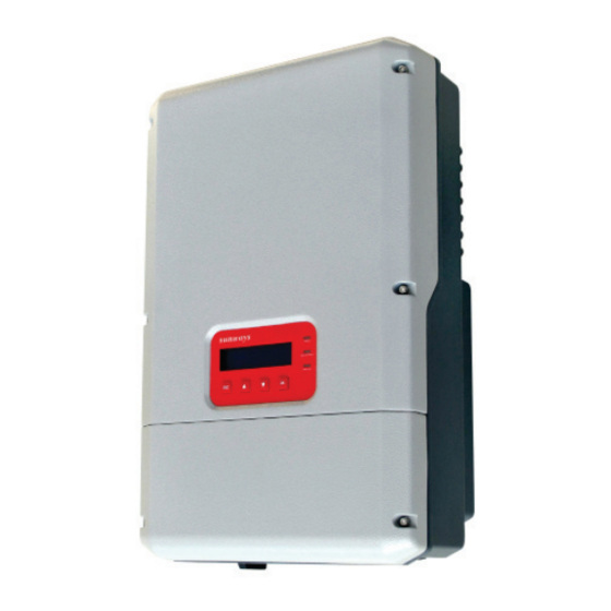
- Page 1 User Manual Sunways Solar Inverter NTX 3000/4000/5000/6000 english...
- Page 2 SUNWAYS AG. SUNWAYS AG makes no representation, express or implied, with respect to this documentation or any of the equipment and/or software it may describe, including(with no limitation) any implied warranties of utility, merchantability, or fitness for any particular purpose.
-
Page 3: Important Safety Instructions
Important Safety Instructions IMPORTANT SAFETY INSTRUCTIONS Save these instructions NOTICE This manual contains important instructions for NTX inverter, that must be followed during installation NOTICE is used to address practices not related to and maintenance of the inverter. personal injury. The NTX is designed and tested according to inter- Other symbols in this document national safety requirements, but as with all electri-... - Page 4 DC current filters behind the fans. For all repair and main- tenance, always return the unit to an authorized Sunways Service Center. Before installing or using the NTX, read all of the instructions, cautions and warnings in the user manual.
-
Page 5: Table Of Contents
Contents Contents Notes on this manual Validity Target group Storage of the documentation Additional information Nomenclature Safety Appropriate usage Anti-Islanding protection PV series fusing Operating temperature Interconnection code compliance FCC compliance Safety instructions Installation overview Unpacking and inspection Scope of delivery Product label Mounting Safety... - Page 6 Contents Opening wiring cover of NTX inverter AC wiring AC voltage configuration AC wiring procedure DC wiring Configuring the DC input channel DC wiring procedure Connection to a single PV array (NTX 4000/5000/6000) Parallel Connection to 2 PV arrays (NTX 4000/5000/6000) Two MPPTS connection to 2 PV arrays or 4 PV arrays (NTX 4000/5000/6000) Connection to 1 PV array or 2 PV arrays...
- Page 7 Contents Technical data 10.1 FCC compliance information 10.2 NTX wiring diagrams NTX connections for 208 V and 240 V AC grids NTX connections for 277 V AC grids 10.3 Technical data 10.4 Trip limits/trip times Contact Notes...
-
Page 8: Validity
Keep all NTX manuals in a convenient place for future reference. Additional information You will find further information on special topics in the download area at WWW.SUNWAYS.EU/EN. Nomenclature In this document SUNWAYS AG is referred to the fol- lowing as Sunways. -
Page 9: Safety
2 Safety Safety Appropriate usage The NTX is a DC to AC grid-tied utility interactive inverter for use with photovoltaic (PV). In general, the NTX takes power from a DC source (PV modules) and converts it to AC power for the utility grid. This power is delivered first to local loads (household appliance, lights, motor loads, etc.), with any excess power fed to the utility. -
Page 10: Anti-Islanding Protection
2 Safety Anti-Islanding protection Interconnection code compliance Islanding is a condition that can occur if the utility The NTX has been tested and listed by Canadian grid is disconnected while the NTX is operating and Standards Association to meet the requirements of the remaining load is resonant at 60 Hz and matches UL 1741 Static Inverters and Charge Controller for the output of the NTX perfectly. -
Page 11: Safety Instructions
2 Safety Safety instructions Installation overview This section provides a brief overview of the installa- tion process of NTX. Section 3: Unpacking and inspection This section provides instructions and information DANGER for unpacking the NTX and inspecting it for shipping ·... -
Page 12: Scope Of Delivery
If you need assistance with a damaged NTX, contact it, report the damage immediately to your Sunways your Sunways dealer or Sunways. Contact informa- dealer and to the shipping company that delivered tion is provided in section “11 Contact”, see page... -
Page 13: Product Label
3 Unpacking and inspection Product label The product label provides basic information of the inverter. Pay special attention to the type of inverter and other specifications. -
Page 14: Safety
4 Mounting Mounting Package inspection Safety NOTE The distributor delivered your NTX inverter to the carrier safely packaged and in perfect condi- WARNING tion. Upon acceptance of the package, the carrier The electrical installation of the NTX inverter must assumes responsibility for its safe delivery. In spite be performed in accordance with the electrical stan- of careful handing, transportation damage to the dards prescribed by the local regulations and by the... -
Page 15: Installation Precaution
Allow sufficient room around the inverter to Recommended arrangement enable easy installation and removal from the mounting surface. WARNING Not installing the inverter in the place mentioned above may cause the malfunction of the system. Sunways will not compensate the fault caused by the above situation. -
Page 16: Preparation
+5° NOTE When the wall is made of a different material (other than concrete), the installation should be done using adequate mounting material. Sunways recom- mends always using stainless steel screws. NOTE The size of the holes Vertical mounting is propositional. Tilted mounting is permitted, but will reduce heat dissipation and result in self-derating. - Page 17 4 Mounting Installation of wall plug NOTE The bracket needs to be mounted vertically to the wall and the side with the hook (shown as pos C in the next figure) should be mounted with the hook pointing upward as shown in the figure. 3.
- Page 18 4 Mounting 5. Lock the inverter and the bracket with lock for safety. Lock the inverter 6. Complete the installation process.
- Page 19 5 Electrical connection Electrical connection · Maximum array DC current input to each MPPT circuit: 17.5 A DC under any condition. For NTX 6000 models, 14.5 A DC under any condition, for NTX 5000 models, 11 A DC under any condi- tion, for NTX 4000 models, 17.5 A DC under any condition, for NTX 3000 models (only one MPPT WARNING...
-
Page 20: General Electrical Connection Procedure Of Ntx Inverter
5 Electrical connection General electrical connection procedure of NTX inverter The DC input from the PV arrays and the output to the AC utility grid connect to the inverter inside the NTX inverter case. AC, DC and COM knockouts are provided on the bottom of the NTX inverter. -
Page 21: Pin Definition
5 Electrical connection Pin Definition RS485 RJ45 Pin Definition P1 and RS485 are as the following figure. Code Name Description RS 485-TX+ RS 485-TX- RS 485-RX+ RS 485-RX- Ethernet RS485 RS485 RS485 1 2 3 4 5 6 7 8 9 10 11 RS485 Signal Lock Terminal Pin Definition Code... - Page 22 5 Electrical connection Models Wire size AWG Temperature Torque min-max °C In-bs NTX 6000 AC field wiring terminals 1.69 DC field wiring terminals 8-10 1.69 Grounding Electrode 5.08 NTX 5000 AC field wiring terminals 1.69 DC field wiring terminals 8-12 1.69 Grounding Electrode 5.08...
-
Page 23: Wiring Procedure Of Ntx Inverter
5 Electrical connection Wiring procedure of NTX inverter Opening wiring cover of NTX inverter 1. Disconnect the inverter from the AC Grid by opening all AC breakers/disconnects and turn the integrated DC disconnect OFF. 2. Carefully cover all PV modules using opaque material. -
Page 24: Ac Voltage Configuration
5 Electrical connection 2. If adjustment is necessary, choose the wire with AC voltage configuration the correct voltage for your application and tighten all wires on the right terminal block with The NTX may be easily configured for the different enough torque described in section “5.1 General grid types commonly found in the U.S. -
Page 25: Ac Wiring Procedure
5 Electrical connection 10. Verify that all connections are correctly wired and properly torqued. Pull on the cable in order to make sure that it is sufficiently fixed in the terminal. WARNING The NTX 3000/4000/5000 may not be connect to a 277 V grid. -
Page 26: Dc Wiring
5 Electrical connection DC wiring If the inverter is configured as two individual MPPTs, the max current for each channel shall not exceed This section provides complete, step-by-step proce- 17.5 A DC for each input channel (NTX 6000), 14.5 A dures for wiring the DC input from the PV array to DC (NTX 5000), 11 A DC (NTX 4000). -
Page 27: Dc Wiring Procedure
5 Electrical connection 4. Turn AC breaker/disconnect ON. Ethernet RS485 GridMode: 240V ² MPPT Input: 2 DC wiring procedure 1– 1– 2– 2– 1. Cover all PV modules using opaque material. 2. Turn AC breaker/disconnect OFF. 3. Turn the integrated DC disconnect OFF. 4. -
Page 28: Parallel Connection To 2 Pv Arrays (Ntx 4000/5000/6000)
5 Electrical connection Parallel Connection to 2 PV arrays If the inverter configured as two individual MPPTs (NTX 4000/5000/6000) connect to 4 PV arrays, the max total current for PV arrays connect terminals “PV1±” or “PV2±” shall not be exceed 17.5 A DC for each input channel (NTX 6000), 14.5 A DC (NTX 5000), 11 A DC (NTX 4000). -
Page 29: Communication Wiring
5 Electrical connection Communication wiring 1. Remove the covers on RS485 and Ethernet knockouts. WARNING If the inverter connect to 2 PV arrays, the max total 2. Install two 1/2 in. conduit fitting in the RS485 current for PV arrays connect terminals “PV1±” shall and Ethernet knockouts (the knockout on the not be exceed 17.5 A DC for the single input channel bottom of the NTX inverter). - Page 30 5 Electrical connection SolaPower Manager Ethernet RS485 Router adapter Ethernet RS232 NOTE The RJ485 pin definition refer to section “5.1 General electrical connection procedure of NTX inverter”, see page 20. NOTE When using a third-party RS485 cables to connect the inverters, attach the supplied ferrite cores to the RS485 cables as shown.
- Page 31 6 Commissioning Commissioning All NTX inverters require that PV array normally operates in an ungrounded configuration. As WARNING required by UL 1741 update, the GFCI protection is active whenever there is sufficient DC voltage to If there is a ground fault in the array, the message feed PV power into the utility grid in the NTX.
-
Page 32: Led Indicators
7 Display and messages Display and messages · The green “Normal” LED indicates that the NTX inverter is operating correctly. This LED stays on steady upon start-up, during the system check routine. If the system is all right, the system will go to the running state. -
Page 33: Available Data
1. Starting up (remain 5 seconds) · Current of photovoltaic array 1 · Voltage of photovoltaic array 2 Welcome to use · Current of photovoltaic array 2 Sunways Inverter · Serial number/Part number · Firmware revision code 2. Waiting · Daily energy After starting up the system go to waiting state, ·... -
Page 34: Default Menu
-key; If you want quit Main Menu, press the -key, and LCD will turn to the default menu. Welcome to use Checking. Sunways Inverter Please Wait Running Menu Welcome to use Checking.. Waiting. Sunways Inverter... -
Page 35: Setting Menu
7 Display and messages T-mon:000.0 h E-mon:000.0 KWh Pin1:0000 W Pin2:0000 W T-mon: Pin1: Input power of channel 1 This month’s lifetime counter of energy trans- Pin2: Input power of channel 2 ferred to the grid. E-mon: Pin:0000 W This month’s energy transferred to the grid. In a configuration with one input connected and T-tot:000.0 h a second input connected in parallel, this screen... - Page 36 7 Display and messages · If the password is wrong, the LCD will give the Or else, the LCD will give the message, and your message: selection will retain the previous setting. Incorrect! Setting Lose! Input again! Please check it! And then turn to the password input screen Press ESC key to quit and go back to the previous again.
- Page 37 7 Display and messages New Password: · Press -key to enter the setting mode which you selected. This function is used to change the default pass- word 0000. · Press the -key to scroll numbers backwards (from 9 to 0). To set your personal code, use the display keys as follows: ·...
- Page 38 7 Display and messages Operation guide · Press the -key to scroll numbers backwards (from 9 to 0). · Press the - or -key to scroll screen and select your submenu. · Press the -key to scroll numbers from 0 to 9. ·...
-
Page 39: Event
Event Service The Event Menu has two submenus: The service Menu contains some system info, such as serial number, hardware version number, software version number and contacts about Sunways. The Error Log screens messages as follow: Operation Log · Press the - and -keys to scroll through items. -
Page 40: General
· If the system problem persists, contact Sunways technical support at: Tel: 49(0) 753199677-0. Email: info@sunways.de In order to better assist you when contacting Sun- ways, please provide the following information. -
Page 41: Messages And Error Codes
8 Troubleshooting Messages and Error Codes The system status is identified through message or error codes appearing on the LCD. When the system appears error status, the LCD will show correspond- ing message. The table that follows summarizes the messages that can be displayed. Message Code Description... - Page 42 8 Troubleshooting Message Code Description Solutions No Utility Missing Grid · Check whether AC grid(voltage and frequency) is beyond the scope; · Check whether the connection of AC side is correct; · If still at fault, please ask for help. Comm loss Communication abnormity Ask for help if still at fault after...
- Page 43 8 Troubleshooting Message Code Description Solutions DC Reverse DC Reverse · Check whether the output voltage of PV array is in the allowing range. · Check whether the insulation of PV cable is good; · Inspect whether the installation is correct according to the manual.
-
Page 44: Cleaning The Fans
9 Maintenance Maintenance 4. Screw up 4 screws on the fan screen and remove it carefully because the fan mounted behind and The NTX is designed to provide many years of trou- the cables are not so long. ble-free service. Performing regular maintenance will help ensure the long life and high efficiency of 5. -
Page 45: 10.1 Fcc Compliance Information
· Consult the dealer or an experienced radio/TV technician for help. · The user is cautioned that changes or modi- fications not expressly approved by Sunways could void the user’s authority to operate this equipment. -
Page 46: 10.2 Ntx Wiring Diagrams
10 Technical data 10.2 NTX wiring diagrams NTX connections for 208 V and 240 V AC grids Utility Ground Equipment Ground Main Neutral Breaker Size PV– N L1 L2 PE 2p 50 Amp AC Switch PV– Array Distribution Panel Earth Ground NTX connections for 277 V AC grids Utility Ground... -
Page 47: 10 Technical Data
10 Technical data 10.3 Technical data Model NTX 3000 NTX 4000 NTX 5000 NTX 6000 PV generator connection Peak power tracking voltage 200 V…500 V Range of input operating 100 V…550 V voltage 400 V Normal input operating voltage Maximum array input power 3850 W 5050 W 6300 W... -
Page 48: 10.4 Trip Limits/Trip Times
Model NTX 3000 NTX 4000 NTX 5000 NTX 6000 Efficiency Peak inverter efficiency 97.6% 97.7% 97.8% 97.8% CEC weighted efficiency at 208 V 96.5% 97.0% 97.0% 96.5% CEC weighted efficiency at 240 V 97.0% 97.0% 97.0% 97.0% CEC weighted efficiency at 277 V 97.0% Ambient condition Ambient Temperature range... - Page 49 10 Technical data Nominal voltage Trip limit Trip voltages Trip voltages Trip times line to neutral line to line 208 V Adjustable Adjustable 0.01 s 52.0 V~98.8 V 104.0 V ~197.6 V (default 52.0 V) (default 104.0 V) Adjustable Adjustable Adjustable 57.2 V~98.8 V 114.4 V~197.6 V...
- Page 50 10 Technical data Nominal voltage Trip limit Trip voltages Trip voltages Trip times line to neutral line to line 277 V Adjustable 0.01 s 138.5 V~263.2 V (default 138.5 V) Adjustable Adjustable 152.4 V~263.2 V 0.16 s~10 s (default 243.8 V) (default 1.67 s) 110% Adjustable...
- Page 51 11 Contact 11 Contact If you have any questions about NTX inverter, please call service support hotline: +49(0) 753199677-0. Please keep following information to better our service for you. · Inverter’s Model; · Inverter’s Serial No.; · Communication Method; · PV modules’...
- Page 52 12 Notes 12 Notes...
- Page 53 12 Notes...
- Page 54 12 Notes...
- Page 55 C&F | Kommunikation und Dokumentation, Villingen-Schwenningen · www.cundf.de...
- Page 56 Sunways AG Photovoltaic Technology Max-Stromeyer-Strasse 160 D - 78467 Konstanz Telefon +49 (0)7531 996 77-0 Fax +49 (0)7531 996 77-444 E-Mail info@sunways.de www.sunways.de Technische Hotline +49 (0)7531 996 77-577...
Need help?
Do you have a question about the NTX3000 and is the answer not in the manual?
Questions and answers