Sunways STS-3KTL User Manual
Grid-connected pv inverter single phase dual mppt
Hide thumbs
Also See for STS-3KTL:
- Manual (28 pages) ,
- Quick installation manual (2 pages) ,
- User manual (28 pages)

Related Manuals for Sunways STS-3KTL


Summary of Contents for Sunways STS-3KTL
- Page 1 Grid-connected PV Inverter S i n g l e P h a s e D u a l M P PT User Manual STS-3K/3.6K/4.2K/4.6K/5K/6KTL Ningbo Sunways Technologies Co., Ltd.
-
Page 3: Table Of Contents
CONTENTS 1.Preface .........................5 1.1 Overview ......................5 1.2 Target Groups ....................5 2.Safety Instructions ....................5 2.1 Safety Notes ....................5 2.2 Statement ......................5 2.3 Important Safety Matters ................6 2.4 Symbols Explanation ..................7 3. Product Introduction ...................9 3.1 Basic Features ....................9 3.2 Appearance Introduction ................10 3.3 Display Interface ..................12 3.4 Packing list....................13 4. - Page 4 Attention The products, services or features you purchase are subject to the commercial contracts and terms of Ningbo Sunways technologies Co., Ltd. All or part of the products, services or features described in this document may not be within your purchasing or using scope.
-
Page 5: Preface
2.2 Statement Ningbo Sunways technologies Co., Ltd. has the right not to undertake quality assurance in any of the following circumstances: 2.2.1 Damages caused by irregular transportation. -
Page 6: Important Safety Matters
2.2.2 Damages caused by incorrect storage, installation or use. 2.2.3 Damages caused by installation and use of equipment by non-professionals or untrained personnel. 2.2.4 Damages caused by failure to comply with the instructions and safety warnings in the products and documents. 2.2.5 Damages of running in an environment that does not meet the requirements stated in the document. -
Page 7: Symbols Explanation
2.4 Symbols Explanation This chapter mainly elaborates the symbols displayed on the inverter, nameplate and packing box. 2.4.1 Symbols on the Inverter Symbol Description Inverter status indicator. Inverter running indicator. Grounding symbol, the inverter casing needs to be properly grounded. 2.4.2 Symbol on the Inverter nameplate Symbol Description... - Page 8 2.4.3 Symbol on the Packing box Symbol Description Handle with care. This side up. Keep dry. Stacked layers.
-
Page 9: Product Introduction
3.1.3 Applicable grid type The applicable grid types for the Sunways STS 3~6kW series are TN-S, TN-C, TN-C-S and TT. When applied to the TT grid, the voltage of N to PE should be less than 30V. See Figure 3-1 for details: 3.1.4 Storage conditions... -
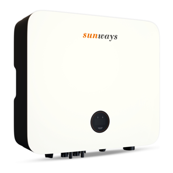
Page 10: Appearance Introduction
3.2 Appearance Introduction 3.2.1 Inverter front view, as shown in Figure 3- 2: 410mm Logo Display Figure 3- 2 Front view 3.2.2 Inverter side view, as shown in Figure 3-3: 120mm Name Plate Figure 3- 3 Side view... - Page 11 3.2.3 Inverter bottom view, as shown in Figure 3- 4: DC Switch Back Rail DC Input Terminal Com Port Figure 3-4 Bottom view 3.2.4 Inverter back view, as shown in Figure 3- 5: Back Rail Vent Valve Figure 3-5 Inverter back view...
-
Page 12: Display Interface
3.3 Display Interface sunways Figure 3-6 Display interface Item Indicator Status Description No input voltage detected or input voltage is too low. Slow flashing Inverter powered on, waiting for the grid connection. Power Indicator Quick flashing Inverter detected grid power and entered self-test status. -
Page 13: Packing List
Figure 3- 7 Packing list 4. Product Installation 4.1 Selection of Installation Location The Sunways STS 3~6kW series is designed with IP65 protection for indoor and outdoor installations. When selecting an inverter installation location, the following factors should be considered: 1) The wall on which the inverter is mounted must be strong and can withstand the weight of the inverter for a long time. - Page 14 Figure 4-1 Recommended installation location Warning Do not put flammable and explosive articles around the inverter. 4.1.2 The requirements for inverter installation spacing are shown in Figure 4-2: 300mm 300mm 300mm Figure 4-2 Recommended installation space 4.1.3 The installation angle of the inverter is recommended as shown in Figure 4-3: Figure 4-3 Recommended installation angle...
-
Page 15: Mounting The Inverter
4.2 Mounting the Inverter 4.2.1 Wall bracket installation Dimensions of wall bracket, see Figure 4-4: 220mm 16mm 110mm 110mm 10mm FRONT Figure 4-4 Dimensions of wall bracket 1) Use the wall bracket as the template to mark the position of 4 holes on the wall. See Figure 4-5 for details: Figure 4-5 Mark the hole position... - Page 16 2) Use an electrical driller with 10mm diameter bit to drill 4 holes on the wall and make sure hole depth is 80mm. Before drilling, make sure to avoid the buried water tube and Warning electric wires in the wall to avoid danger. 3) Insert the expansion tubes into the holes and tighten them, then fix the bracket onto the wall with expansion screws by using a cross screwdriver, as shown in Figure 4-6: Figure 4-6 Fix the wall bracket...
-
Page 17: Electrical Connection
Do not use other brands or other types of terminals other than the Attention terminals in the accessory package. Sunways has the right to refuse all damages caused by the mixed-use of terminals. Moisture and dust can damage the inverter, ensure the cable gland Attention is securely tightened during installation. - Page 18 3) Disassemble the connector in the accessory bag, as shown in Figure 4-9: Figure 4-9 4) Insert the DC cable through the DC connector nut into the metal terminal and press the terminal with a professional crimping plier (pull back the cable with some power to check it’s tight enough or not), as shown in Figure 4-10: C r i mpi n g P l i e r Figure 4-10...
- Page 19 Figure 4-12 4.3.2 Connection of AC output The Sunways STS 3~6kW series single phase inverter applies to the single-phase power grid with a voltage of 220/230V and a frequency of 50/60Hz. The recommended cable and AC breaker for the Sunways STS 3~6kW series single phase...
- Page 20 2) According to the table above, select an appropriate cable, peel the insulation sleeve of AC cable off for 50mm, and peel off the end of L /PE / N wires for 8mm, as shown in Figure 4-14: Wire Diameter:10-14mm St r i p Le n gt h: 8mm 50 mm Figure 4-14...
- Page 21 5) Connect the AC connector to the inverter AC terminal, and the slight click represents the connection is in the place. As shown in figure 4-17: Figure 4-17 Connect the AC connector 4.3.3 External ground connection Danger Do not connect the N-wire as a protective ground wire to the inverter casing.
-
Page 22: Monitoring Device Installation
Figure 4-18 Grounding terminal connection 4.4 Monitoring Device Installation Sunways STS 3~6kW series single phase inverter supports WiFi, GPRS and RS485 communication, you can choose according to your specific needs. Plug the WiFi or GPRS module into the COM port in the bottom of inverter by following the direction the side with indicator is up (as shown in Figure 4-19). -
Page 23: Power Limiting Device & Dred Connection
4.5 Power Limiting Device & DRED Connection An external CT is needed to realize the power export limiting function on Sunways STS 3-6kW series inverter. You may refer to the diagram and steps below to complete the CT installation. - Page 24 (DRM). This function is for inverter that comply with AS/ NZS4777.2:2015 standard. Sunways STS 3-6kW series single phase inverter is fully complied with all DRM. The 6pin connector in the bottom of inverter is used for DRM connection.
-
Page 25: System Layout Of Units Without Integrated Dc Switch
4.6 System Layout of Units Without Integrated DC Switch Local standards or codes may require that PV systems are fitted with an external DC switch on the DC side. The DC switch must be able to safely disconnect the open-circuit voltage of the PV array plus a safety reserve of 20%.Install a DC switch to each PV string to isolate the DC side of the inverter. -
Page 26: General Operation
6. General Operation 6.1 Display Operation When the inverter is turned on, the following interfaces will be displayed on the OLED display, and you can check the information and modify the parameters of the inverter by short or long pressing the button. Please refer to the following display operation flow for details: Short press(1s), switch window Firmware Updating... -
Page 27: Troubleshooting
7. Troubleshooting 7.1 Fault Messages Sunways STS 3~6kW series single phase inverter is designed in accordance with grid operation standard, and conform to the requirements of the safety and EMC. The inverter had passed a series of rigorous tests to ensure it runs sustainably and reliably before shipment. -
Page 28: Technical Parameters
8. Technical Parameters Model STS-3KTL STS-3.6KTL STS-4.2KTL STS-4.6KTL STS-5KTL STS-6KTL Start-up Voltage (V) Max. DC Input Voltage (V) Rated DC Input Voltage (V) MPPT Voltage Range (V) 100~550 100~550 100~550 100~550 100~550 100~550 Full power MPPT voltage range (V) 130~500... - Page 29 Model STS-3KTL STS-3.6KTL STS-4.2KTL STS-4.6KTL STS-5KTL STS-6KTL Max. Efficiency 98.1% 98.1% 98.1% 98.1% 98.1% 98.1% Effi- European Efficiency 97.5% 97.5% 97.5% 97.5% 97.5%w 97.5% ciency MPPT Efficiency 99.9% 99.9% 99.9% 99.9% 99.9% 99.9% DC Reverse Polarity Protection Integrated Insulation Resistance Protection...
- Page 30 Address: No. 1, Second Road, Green Industrial Zone, Chongshou Town, Cixi City, ZheJiang Province, PEOPLE’S REPUBLIC OF CHINA Website: www.sunways-tech.com Service Mail: service@sunways-tech.com Hotline: +86 400-9922-958...
Need help?
Do you have a question about the STS-3KTL and is the answer not in the manual?
Questions and answers