
Subscribe to Our Youtube Channel
Related Manuals for Rocktron Taboo ARTIST


Summary of Contents for Rocktron Taboo ARTIST
- Page 1 ANUAL May be covered by one or more of the following: U.S. Patents #4538297, 4647876, 4696044, 4745309, 4881047, 4893099, 5124657, 5263091, 5268527, 5319713, 5333201, 5402498 and 5493617. Other patents pending. Foreign patents pending.
- Page 2 Your Taboo Artist footpedal has been tested and complies with the following Standards and Directives as set forth by the European Union: Council Directive(s): 89/336/EEC (Electromagnetic Compatibility) Standard(s): EN55022, EN50082-1 This means that this product has been designed to meet stringent guidelines on how much RF energy it can emit, and that it should be immune from other sources of interfer- ence when properly used.
- Page 3 Rocktron Corporation 2870 Technology Drive Rochester Hills, MI 48309 Phone: (248) 853-3055 (248) 853-5937 Fax: WWW: http://www.rocktron.com E-mail: rocktron@eaglequest.com F398 0498 098-0218...
- Page 6 NOTE: IT IS VERY IMPORTANT THAT YOU READ THIS SECTION TO PROVIDE YEARS OF TROUBLE FREE USE. THIS UNIT REQUIRES CAREFUL HANDLING. • All warnings on this equipment and in the operating instructions should be adhered to and all operating instructions should be followed. •...
- Page 9 control control provides access to each of the primary functions of the current Artist preset. These include effects, MIDI functions and various utility functions. The functions that are available for a particular preset depend on which configuration is selected for the current preset (see page 18 for more information). control Once a function heading has been selected via the control, the...
- Page 10 switch The function of this switch is dependent on the status of the “2nd” LED. When the Artist is in “normal” mode (2nd LED off) this switch is used to instantly recall the third preset within the current bank. When the Artist is in “2nd” mode (2nd LED on) this switch is used to mute the outputs of the Artist.
- Page 11 jack This ¼” unbalanced mono jack accepts the output from a guitar. jack This ¼” jack provides the left unbalanced mono output of the Artist for use with a guitar amplifier. This jack also allows for the connection of stereo headphones (600 ohms impedance or greater).
- Page 12 jack This 5-pin DIN connector must be connected to the M jack of the transmitting MIDI device via a standard MIDI cable, or to the M jack of the preceding device (if the Artist is within a chain of MIDI devices). jack This standard 5-pin DIN connector can be connected to the M jack of another device...
- Page 19 1. Set the controller number for the first parameter to be controlled. 2. Select the parameter to be controlled. 3. Select upper and lower limits for the parameter that the controller will not exceed (if desired). 4. Repeat steps 1-3 for up to eight controllers. Example: Configuring an Artist preset to control the Wah Frequency parameter with the expression pedal To access the Controller Assign function, turn the After selecting a controller number, press the...
- Page 20 Turn the control one step clockwise to display Turn the control one step clockwise to access the the current upper limit parameter for the current controller. lower limit parameter for the current controller. LLIM C1 -¥ ulim c1 Use the control to select the highest value that the Use the control to select the lowest value which the...
- Page 21 1. A preset is currently recalled in which the expression pedal controls the VOLUME parameter, and the pedal is used to set the VOLUME at 48. 2. Another preset is then recalled which has the VOLUME STATUS parameter stored ON, and the VOLUME parameter is stored at 75.
- Page 22 • H GAIN ISTORTION HORUS ELAY EVERB • H GAIN ISTORTION LANGE ELAY EVERB • H GAIN ISTORTION REMOLO ELAY EVERB • H GAIN ISTORTION ITCH HIFT ELAY EVERB • W GAIN ISTORTION ELAY EVERB • P HASE HIFT GAIN ISTORTION ELAY EVERB...
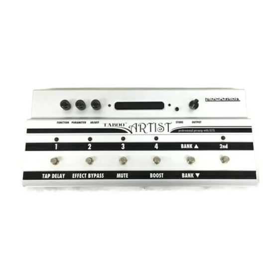
- Page 23 Turn to select Turn to select a parameter Turn to alter the value of a function. within the selected function. the selected parameter. Artist top panel...
- Page 24 OUTPUT The OUTPUT parameter determines whether the output of the Artist is a stereo (left and right) signal or two mono signals. This SPEAKER SIMULATOR parameter under the Global function allows you to globally (all presets) SPKR SIM lock the Speaker Simulator off (LOCKOFF) so that it will always be off for all presets—regardless of the status of the “SPKR SIM”...
- Page 25 VOLUME The VOLUME parameter determines the overall signal level of the current preset. LEFT OUT LVL The LEFT OUT LEVEL parameter allows you alter the level of the left channel output of the current preset independent of the right channel. RIGHT OUT LVL The RIGHT OUT LEVEL parameter allows you alter the level of the right channel output of the current preset independent of the left channel.
- Page 26 GAIN The GAIN parameter determines the amount of gain in the distortion stage. VARlAC ADJUST The VARIAC ADJUST parameter adjusts the level at which the preamp stage in the Artist begins to distort. A Variac is a voltage attenuating device that plugs into an AC wall outlet and allows you to adjust the voltage level to any device that is plugged into it.
- Page 27 GAIN The GAIN parameter determines the amount of gain in the distortion stage. DIST The DISTORTION TYPE parameter allows you to select between four different distortion types — Solid State, Pentode, Triode A and Triode B. The Solid State setting provides the hardest clipping, while the Pentode type provides a softer clipping and the Triode A and B types provide the softest clipping.
- Page 28 ® HUSH HUSH HUSH HUSH HUSH HUSH HUSH HUSH I/O The HUSH I/O parameter simply determines whether the HUSH ® circuit is active for the current preset. HUSH THRESH The HUSH THRESHOLD parameter determines the level at which downward expansion begins. For example, if the HUSH THRESHOLD was set at -20dB and the input signal dropped below -20dB, downward expansion would begin.
- Page 29 LF LEVEL The pre-LF (low frequency) LEVEL parameter allows you to cut or boost the low frequencies from -15dB to +6dB prior to the distortion stage. This EQ section is a shelving-type. LF FREQ The pre-LF (low frequency) FREQUENCY parameter allows you to select a frequency band with an upper frequency between 63Hz and 500Hz to be cut or boosted by the pre-LF LEVEL parameter.
- Page 30 BASS LVL The post-BASS LEVEL parameter allows you to cut or boost the low frequencies by 15dB after the distortion stage. BASS FREQ The post-BASS FREQUENCY parameter allows you to select a center frequency between 63Hz and 500Hz to be cut or boosted by the post-BASS LEVEL parameter. BASS BW The post-BASS BANDWIDTH parameter determines (in octaves) the width of the selected bass band.
- Page 31 COMPRESSOR I/O The COMPRESSOR IN/OUT parameter determines whether the compressor is active for the current preset. COMP THRESH The COMPRESSOR THRESHOLD parameter determines the input level (in dB) at which compression will begin. Lower settings of this parameter will result in more compression. COMP ATTACK The COMPRESSOR ATTACK parameter determines the speed (in milliseconds) in which the compressor will reach its maximum compression level after the input signal has exceeded the threshold level (set by the...
- Page 32 Note: The parameters provided in this function are operational only when the SPKR SIM parameter under the GLOBAL FUNCTION is stored UNLOCK, LOCK L or LOCK B. SPKR SIM I/O The SPEAKER SIMULATOR parameter allows you to select whether the Speaker Simulator is on for BOTH outputs, on for only the LEFT output or OFF.
- Page 33 WAH-WAH I/O The WAH-WAH I/O parameter determines whether the wah-wah is active for the current preset. WAH FREQ The WAH FREQUENCY parameter allows you to manually sweep the frequency range of the wah-wah via control. Selecting a frequency for this parameter and storing the WAH-WAH parameter IN allows you to use the wah-wah as a fixed wah.
- Page 34 PHASER I/O The PHASER IN/OUT parameter determines whether the Phaser is active for the current preset. DEPTH The DEPTH parameter determines the modulation depth of the phase shift effect. Higher parameter settings result in the sweep of the filtering effect occurring over a wider frequency range. RATE The RATE parameter determines the speed at which the phase shifted signal is modulated.
- Page 35 LEVEL 1 The LEVEL 1 parameter determines the volume of Voice 1 relative to Voice 2. Tip: Keep the settings of these levels high and use the DIR/EFF mix parameter in the Mixer function to control the overall amount of flanged signal. PAN 1 The PAN 1 parameter allows you to pan Voice 1 to the left or right channel.
- Page 36 TREMOLO I/O The TREMOLO IN/OUT parameter determines whether the Tremolo is active or bypassed for the current preset. LOCATION The LOCATION parameter determines whether the Tremolo is located Pre-Reverb or Post-Reverb. Most vintage amplifiers configured the Tremolo (or vibrato) Post-Reverb. DEPTH The DEPTH parameter determines the amount of modulation for the Tremolo signal.
- Page 37 PITCH SHIFT I/O The PITCH SHIFT IN/OUT parameter determines whether the Pitch Shifter is active or bypassed for the current preset. LEVEL The LEVEL parameter determines the volume of the pitch shifted signal. The DIR/EFF MIX parameter in the Mixer function also affects this volume. The PAN parameter allows you to pan the shifted signal to the left or right channel.
- Page 38 PARAMETER CORRESPONDING VALUE INTERVAL +1200 1 Octave +1100 Major 7th +1000 minor 7th +900 Major 6th +800 minor 6th +700 perfect 5th Voices above the input signal +600 diminished 5th +500 perfect 4th +400 Major 3rd +300 minor 3rd +200 Major 2nd +100 minor 2nd...
- Page 39 CHORUS I/O The CHORUS I/O parameter determines whether the Chorus is active or bypassed for the current preset. LEVEL 1 / LEVEL 2 The LEVEL parameters determine the volume of Voice 1 and Voice 2 relative to each other. The DIR/EFF MIX parameter in the Mixer function also determines the Chorus level.
- Page 40 DELAY The DELAY parameter determines whether the Delay function is active or muted for the current preset. MUTE TYPE The MUTE TYPE parameter allows for muting the delay at its input (PRE), its output (POST) or BOTH. Muting the input (PRE) of the delay will not allow any signal to enter the delay section until the delay is switched in.
- Page 41 SOURCE 2 The SOURCE 2 parameter is used to select whether the Source 2 input will be the VOICE 2 output from the previous effect in the signal chain or the direct signal (DIR). DLY HF DAMP The DELAY HIGH FREQUENCY DAMPING parameter controls the amount of high frequency content in the delayed and regenerated signals.
- Page 42 REV INPUT The REVERB INPUT parameter determines whether the input to the Reverb section is ACTIVE (passing a signal) or MUTED (will not pass a signal). MIX DIR/DLY The MIX DIRECT/DELAY parameter is used to define the ratio of direct signal to delayed signal to be input to the reverb section.
- Page 43 The Artist's 252 presets are arranged as 63 banks (or groups) of four, where the switch is used to select the desired bank of presets. Once the desired bank has been selected, individual presets within that bank are then instantly recalled via switches through .
- Page 44 If the desired preset is located below the current bank, press the 2nd switch to activate the secondary functions of the Artist's switches. The secondary functions are labeled below each switch, and are active whenever the 2nd l.e.d. is lit. Press the switch to "bank down"...
- Page 45 Turn the control to select the function heading which contains the parameter(s) to be edited. **** reverb **** Turn the control to select a parameter to edit. rev decay Turn the control to alter the parameter value. rev decay...
- Page 46 While viewing a function or parameter title, press the button to initiate the store procedure. Once has been pressed, display will alternate between the current destination preset number (to store the preset to) and title and “STORE AT PRESET”. preset title store preset...
- Page 47 Press the button a second time to store the new values into the selected preset destination. The display will briefly flash “STORED” before display- ing the new preset number and title. Turning either the controls before completing this step will cancel the store procedure. s t o r e d If a preset with altered parameters is exited before completing Step 3, all edited parameter values will be lost, and the preset will...
- Page 48 To select a new configuration, turn the control clockwise until “CONFIG SELECT” is displayed. config select Turn the control clockwise to display the current configuration. h g a i n , c r s , d l y , r e v Use the control to scroll through the Artist configurations.
- Page 49 Press the button to initiate the store procedure. The Artist display will alternate between the current preset number/title and “STORE AT PRESET”. preset title store preset The modified preset can either be stored into the current preset location or a different one.
- Page 50 After the parameter values have been stored (Step 6) into a new location, the Artist will display “COPY TITLE TOO?”. This message is displayed only when storing into a new preset location, and allows you to also copy the title from the original preset into the new preset location.
- Page 51 Turn the control clockwise until the Artist displays “TITLE EDIT”. **title edit** Turn the control clockwise to initiate the Title Edit mode. This control is used to select the character location to be edited. A flashing decimal will follow the character currently selected. p.reset title Flashing decimal...
- Page 52 To edit the character in the next position, turn the control one step clockwise. The flashing decimal will move to the next character. mr.eset title Flashing decimal After all the characters have been edited as needed, press the button to save the new title.
- Page 53 The Controller Assignment function allows for specific Artist adjustable parameters to be mapped (or assigned) to a MIDI controller for real-time control by an expression pedal. The Controller Assignment option also lets you store an upper and lower parameter value limit which the controller cannot exceed. For example, when using the expression pedal to send continuous control changes to control the “PITCH”...
- Page 54 Use the control to select the controller to be assigned to the PARA 1 parameter. Any number from 0 to 120 may be selected, as well as OFF (will not respond to MIDI control changes) or PED (where the selected parameter is controlled by the included expression pedal).
- Page 55 After selecting the parameter that you which to assign to a controller, press the STORE button to save it. The Artist will flash “STORED” briefly. s t o r e d The Artist allows you to select upper and lower parameter values which will not be exceeded when used with a MIDI controller.
- Page 56 After selecting a value for the upper limit, press the button to save it. “STORED” will flash briefly on the display. s t o r e d Turn the control one step clockwise to access the lower limit parameter for the current controller. LLIM C1 -¥...
- Page 57 The Artist's Tap Delay feature allows for the current delay time settings to be set on- the-fly (while playing). When activated, tapping the dedicated switch changes the current delay time settings based on the length of time between two taps. The Artist detects the length of time between any two taps that are less than one second apart (if more than one second passes after the first tap, two more taps—less than one second apart—are required to change the delay time again).
- Page 58 Turn the control to display the status for the DELAY 1 param- eter. This parameter determines the formula used to calculate the delay time for Delay 1. delay 1 whole Use the control to select the desired note-type for Delay 1. “NONE” may also be selected to disable the Tap Delay function for Delay 1.
- Page 59 MIDI program changes allow for user-specified MIDI program numbers to be sent when Artist presets are recalled. For example, Artist preset 33 can be set to send MIDI program 58 when it is recalled. Note that the default setting for the Artist MIDI transmit channel is OFF in all presets, therefore no MIDI commands are sent from the Artist when a preset is recalled until it is configured by the user.
- Page 60 Press the button to save the status selection. “STORED” will flash briefly on the display. S T O R E D...
- Page 61 The Artist can receive MIDI commands from other MIDI transmitting devices, as well as transmit MIDI program changes to other MlDI-based equipment when a preset is recalled. The MIDI Channels function allows you to select the MIDI channels that the Artist will receive and transmit MIDI information on.
- Page 62 Press the button to save the new channel that the Artist will receive MIDI commands on. “STORED” will flash briefly on the display. s t o r e d Turn the control one step clockwise to display the current channel that the Artist receives MIDI information on. TRANS CHANL Use the...
- Page 63 Any or all of the Artist presets may be dumped to a sequencer or another Artist via system exclusive messages. The information exchanged when performing a MIDI Dump consists of parameter values, title characters and controller assignment/limit informa- tion. When dumping a single preset into another Artist, the dumped preset may be loaded into any preset location on the receiving Artist.
- Page 64 Turn the controls on both the transmitting and receiving Artists until “MIDI DUMP/LOAD” is displayed on each. midi dump/load midi dump/load Receiving Artist Transmitting Artist Turn the control on each unit one step clockwise to “PR DUMP/ LOAD”. dump/load dump/load Receiving Artist Transmitting Artist On the transmitting Artist, select the preset that is to be dumped.
- Page 65 To initiate the dump, press the button on the transmitting Artist. The transmitting Artist will display the preset number being dumped and “DUMPED”. The receiving Artist will display the preset location being stored to and “RECEIVING...” while it receives and stores the preset parameters and title.
- Page 66 Connect a standard MIDI cable from the MIDI OUT of the transmitting Artist to the MIDI IN on the receiving sequencer. It is important not to allow a looping connection from the MIDI OUT/THRU of the receiving sequencer back to the MIDI IN of the transmitting Artist.
- Page 67 Turn the control on the transmitting Artist until “BULK DUMP/ LOAD” is displayed. bulk dump/load Transmitting Artist Start the sequencer recording. RECORD Press the button on the Artist to initiate the data dump. As the Artist performs the dump, it will display “XXX DUMPED” - where “XXX” repre- sents the data string number currently transmitting (i.e.
- Page 68 Connect a standard MIDI cable from the MIDI OUT of the transmitting sequencer to the MIDI IN on the receiving Artist. It is important not to allow a looping connection from the MIDI OUT/THRU of the receiving Artist back to the MIDI IN of the transmitting sequencer. Turn the control on the receiving Artist until “MIDI DUMP/LOAD”...
- Page 69 Play back the data stored on the sequencer. PLAY The Artist will display each data string as it is being stored. Each data string will appear with the word “LOADED”. After all the user data has been loaded, the Artist will display “LOAD COMPLETE”. load complete Receiving Artist...
- Page 70 The Factory Restore function returns altered Artist presets to their original condi- tion as shipped from the factory. Either the entire Artist memory (all presets) can be restored, a single preset can be restored to any preset location, or the the controller information can be restored.
- Page 71 Turn the control to select the preset location to store the restored preset into. restr 98 to Pressing the button at this time will overwrite the current preset with the displayed factory preset! Press the button to restore the selected factory preset into the selected location.
- Page 72 This procedure will permanently erase all user presets (1-252) and replace them with the original factory presets as shipped from Rock- tron. If you have altered and stored presets which you do not want to erase, do not perform the following procedure. Turn the control clockwise to “FACTORY RESTORE”.
- Page 73 Pressing the button at this time will permanently erase all user presets and replace them with the original factory presets. If you have altered and stored presets which you do not want to erase, turn the control to exit this function immediately. Press the button at this time to initiate the All Restore procedure and erase all current Artist presets, replacing them with the original factory...
- Page 74 The Artist allows you to store the preset that will always be recalled when the unit is first turned on. Use the preset selection switches ( , - ) to select the preset that is to be recalled each time the unit is turned on. preset title Press the...
- Page 75 Error Message Possible Cause Corrective Action MEMORY ERROR CODE BYTE IS NOT CORRECT IN MAKE SURE EEPROM IS TIGHT IN EEPROM MEMORY . SOCKET . MAKE SURE WITHIN CORRECT OPERA TING TEMPERA TURE. DUMP ERROR MIDI INFORMA TION IS BEING DISCONNECT MIDI CORD A T M I D I I N RECEIVED A T THE MIDI IN A T THE OF TRANSMITTING UNIT .
- Page 76 The user interface of the Artist presents its 252 presets such that they are divided into 63 banks, with each bank consisting of 4 presets. This configuration allows for the user to arrange presets into groups (usually by song), with one-button access to up to four presets per song.
- Page 77 Artist MIDI Artist MIDI Artist MIDI Artist MIDI Bank/Preset Program Bank/Preset Program Bank/Preset Program Bank/Preset Program Number Number Number Number Number Number Number Number 25/1 35/1 45/1 55/1 25/2 35/2 45/2 55/2 25/3 35/3 45/3 55/3 25/4 35/4 45/4 55/4 26/1 36/1 46/1...
- Page 78 Model: Taboo Artist Date: March 14, 1998 Version: Key: O = YES X = NO FUNCTION TRANSMITTED RECOGNIZED REMARKS BASIC DEFAULT 1-16 1-16 May be saved in non-volatile memory CHANNEL CHANGED 1-16 1-16 DEFAULT MODE MESSAGES ALTERED NOTE NUMBER TRUE VOICE...
- Page 79 Input Impedance ............. 470 k W Maximum Input Level ........... +20 dBu Input Jack ............... ¼” mono Output Impedance ..........< 150 W Maximum Output Level ........+20 dBu Output Jacks ....... ¼" unbalanced left and right. (Left jack can drive stereo headphones of 600 W or more.) MIDI In ..............
Need help?
Do you have a question about the Taboo ARTIST and is the answer not in the manual?
Questions and answers