Quadra-Fire TOPAZ Direct Vent Room Heater 839-1290 Owner's Manual
Direct vent room heater
Hide thumbs
Also See for TOPAZ Direct Vent Room Heater 839-1290:
Table of Contents
Advertisement
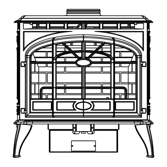
Quartet Front
• Important operating and
maintenance instructions
included.
WARNING: If the information in these
instructions is not followed exactly, a fire
or explosion may result causing property
damage, personal injury, or death.
• Do not store or use gasoline or other flammable
vapors and liquids in the vicinity of this or any other
appliance.
• What to do if you smell gas
- Do not try to light any appliance.
Do not touch any electrical switch. Do not use any
phone in your building.
- Immediately call your gas supplier from a neigh-
bor's phone. Follow the gas supplier's instructions.
- If you cannot reach your gas supplier, call the fire
department.
• Installation and service must be performed by a
qualified installer, service agency, or the gas supplier.
This appliance may be installed as an OEM installation in manufactured
home (USA only) or mobile home and must be installed in accordance with
the manufacturer's instructions and the manufactured home construction
and safety standard, Title 24 CFR, Part 3280 or Standard for Installation
in Mobile Homes, CAN/CSA Z240MH.
This appliance is only for use with the type(s) of gas indicated on the
rating plate.
www.quadrafire.com
TOPAZ
DIRECT VENT ROOM HEATER
Owner's Manual
Installation and Operation
Model:
839-1290
839-1320
839-1340
844-4120
TOPAZ-D-CSB
TOPAZ-D-CWL
CAUTION
DO NOT DISCARD THIS MANUAL
• Read, understand and
follow these instructions
for safe installation and
operation.
In the Commonwealth of Massachusetts:
• installation must be performed by a licensed plumber or gas
See Table of Contents for additional Commonwealth of Mas-
sachusetts requirements.
7009-113G
• Leave this manual with
party responsible for use
and operation.
WARNING
HOT SURFACES!
Glass and other surfaces are
hot during operation AND cool
down.
Hot glass will cause burns.
• Do not touch glass until it is
cooled
• NEVER allow children to touch glass
• Keep children away
• CAREFULLY SUPERVISE children in the same
room as appliance
• Alert children and adults to hazards of high
temperatures
High temperatures may ignite clothing or other
flammable materials.
• Keep clothing, furniture, draperies and other
combustibles away.
fitter.
Installation and service of this appliance should be
performed by qualified personnel. Hearth & Home
Technologies suggests NFI certified or factory-trained
professionals, or technicians supervised by an NFI
certified professional.
R
Portland
Tested and
O-T L
Oregon USA
Listed by
C
US
OMNI-Test Laboratories, Inc.
Solitaire Front
September 1, 2008
Advertisement
Table of Contents

Related Manuals for Quadra-Fire TOPAZ Direct Vent Room Heater 839-1290


Summary of Contents for Quadra-Fire TOPAZ Direct Vent Room Heater 839-1290
-
Page 1: Installation And Operation
Quartet Front • Important operating and maintenance instructions included. WARNING: If the information in these instructions is not followed exactly, a fire or explosion may result causing property damage, personal injury, or death. • Do not store or use gasoline or other flammable vapors and liquids in the vicinity of this or any other appliance. - Page 2 and Welcome to the Quadra-Fire Family Hearth & Home Technologies welcomes you to our tradition of excellence! In choosing a Quadra-Fire appliance, you have our assurance of commitment to quality, durability, and performance. This commitment begins with our research of the market, including ‘Voice of the Customer’...
-
Page 3: Table Of Contents
Section 1: Listing and Code Approvals A. Appliance Certifications ...4 B. Glass Specifications ...4 C. BTU Specifications ...4 D. High Altitude Installations ...4 E. Non-Combustible Materials ...4 F. Combustible Materials ...4 G. Requirements for the Commonwealth of Massachusetts ...5 Section 2: Getting Started A. -
Page 4: Section 1: Listing And Code Approvals
Listing and Code Approvals A. Appliance Certification Topaz MODEL: OMNI Test Laboratories, Inc. LABORATORY: 061-S-24-5 Direct Vent Gas Heater TYPE: STANDARD: ANSI Z21.88a-2000 ּ UL307b CAN/CBA 2.17-M91 The product is listed to ANSI standards for “Vented Gas Appliance Heaters” and applicable sections of “Gas Burning Heating Appliances for Manufactured Homes and Recre- ational Vehicles”... -
Page 5: Requirements For The Commonwealth Of Massachusetts
NOTE: The following requirements reference various Massachusetts and national codes not contained in this document. G. Requirements for the Commonwealth of Massachusetts For all side wall horizontally vented gas fueled equipment installed in every dwelling, building or structure used in whole or in part for residential purposes, including those owned or operated by the Commonwealth and where the side wall exhaust vent termination is less than seven (7) feet above... -
Page 6: Section 2: Getting Started
Getting Started A. Design & Installation Considerations Quadra-Fire direct vent gas appliances are designed to oper- ate with all combustion air drawn from outside of the building and all exhaust gases expelled to the outside. No additional air source is required. CAUTION Check building codes prior to installation. -
Page 7: Section 3: Appliance Location & Clearances A. Selecting Appliance Location
Appliance Location and Clearances NOTE: · Illustrations reflect typical installations and are FOR DESIGN PURPOSES ONLY. · Illustrations/diagrams are not drawn to scale. · Actual installation may vary due to individual design preference. A. Selecting Appliance Location When selecting a location for your appliance it is important to consider the required clearances to walls (see Figure 3.1). -
Page 8: Section 4: Termination Locations
Termination Locations A. Vent Termination Minimum Clearances WARNING Fire Risk. Explosion Risk. Maintain vent clearance to combustibles as specified. • Do not pack air space with insulation or other materials. Failure to keep insulation or other materials away from vent pipe may cause fire. Measure vertical clearances from this surface. - Page 9 = VENT TERMINAL = 12 inches ... clearances above grade, veran- (See Note 1) da, porch, deck or balcony = 12 inches ... clearances to window or door that may be opened, or to per- manently closed window. (Glass) = 18 inches ... vertical clearance to unventilat- ed soffit or to ventilated soffit lo- cated above the terminal *30 inches ...
-
Page 10: Section 5: Vent Information
Vent Information A. Venting Components In order to comply with applicable codes and product warranties, use only following venting components: • Hearth & Home Technologies (HHT) • Simpson Dura-Vent • Selkirk Direct-Temp • Amerivent Direct • Security Secure Vent FIELD-FABRICATED COMPONENTS. -
Page 11: How To Use The Vent Graph
D. How to Use the Vent Graph Measure the vertical distance from the center line of the flue pipe to the center of the 90° elbow. On the graph below, draw a horizontal line from that measurement on the vertical axis across until it intersects with the slanted line. -
Page 12: Horizontal Termination
F. Horizontal Termination Up & Out Installations for Top Vent Type A - Configurations Wall Thimble 90º Degree Elbow Pipe Length Wall Thimble Cover Pipe Length Type B - Rear Installations for Use with Rear Vent Wall Thimble Cover Pipe Length (See Section 12 for conversion kit and venting components.) This is the only venting configuration that requires the use of the rear vent derating orifice that... - Page 13 Step 3. For installations using a round support box/wall thimble (check pipe manufacturer's instructions), mark the wall for a 10 in. x 10 in. (254mm x 254mm) square hole. The center of the square hole should line up with the center line of the horizontal pipe, as shown in Figure 5.5.
- Page 14 8 in. (203mm) 7 in. (178mm) 7 in. (178mm) 6 in. (152mm) Figure 5.7 (NOTE: Some termination caps may cause the vent pipe to be off center on flashing). Ensure that proper clearances to combustible materials are maintained. If you are not using an approved termination cap with a built-in vinyl siding standoff on a building with vinyl siding, a vinyl siding standoff should be installed between the termination cap and the exterior wall (Figure 5.8).
-
Page 15: Vertical Termination
G. Vertical Termination 1. Direct Vent Pipe Storm Collar Firestop Pipe Length Figure 5.10 Step 1. Check the installation instructions for required 1 in. (25mm) clearances (air space) to combustibles when passing through ceilings, walls, roofs, enclosures, attic rafters, or other nearby combustible surfaces. - Page 16 Step 3. To install the round support box/wall thimble cover in a flat ceiling, cut a 10 in. (254mm) square hole in the ceiling, centered on the hole drilled in Step 2. Frame the hole as shown in Figure 5.13. Framing Figure 5.13 Step 4.
- Page 17 Step 9. Twist-lock the vent cap and seal. Note: For multi-story vertical installations, a ceiling firestop is required at the second floor, and any subsequent floors (Figure 5.16). The opening should be framed to 10 in. x 10 in. (254mm x 254mm) inside dimensions, in the same manner as shown in Figure 5.13.
-
Page 18: Cathedral Ceiling
2. Cathedral Ceiling Step 1. Follow installation Steps 1 and 2 under vertical installation section, page 15. Step 2. Using the plumb-bob, mark the center line of the venting system on the ceiling, and drill a small hole through the ceiling and roof at this point. -
Page 19: Class A Metal Chimney
3. Class A Metal Chimney Termination Cap Top Adaptor Existing Metal Chimney System 4 in. (102mm) Flex Pipe Retro Connector Direct Vent Pipe Figure 5.20 CAUTION Ensure that existing chimney is functionally sound and clean. • Have inspection done by qualified chimney sweep or professional installer BEFORE converting to direct vent appliance. -
Page 20: Existing Masonry Chimney
4. Existing Masonry Chimney Type A - Up & Out Installations for Top Vent Configurations Top Adaptor Retro Connector 90° Elbow Direct Vent Pipe Figure 5.24 Page 20 Type B - Hearth Rear Vent Installations for Use With Rear Vent Kit (see Section 12 for conversion kit and venting components.) Termination Cap Flashing... - Page 21 CAUTION Ensure that existing chimney is functionally sound and clean. • Have inspection done by qualified chimney sweep or professional installer BEFORE converting to direct vent appliance. Step 1. Before cutting any holes, assemble the desired sections of direct vent pipe to determine the center of the masonry penetration.
- Page 22 Figure 5.27 Step 8. Secure the top adapter to the flashing. Use three sheet metal screws through the side of the top adapter into the flange on the flashing (Figure 5.28). Twist lock the high wind termination cap on to the top adapter. High Wind Termination Cap Top Adaptor...
-
Page 23: Section 6: Gas Information
Gas Information A. Fuel Conversions Before making gas connections ensure that the appliance being installed is compatible with the available gas type. Any natural or propane gas conversions necessary to meet the appliance and locality needs must be made by a quali- fied technician using Hearth &... - Page 24 Pull off pilot hood and set it aside. Figure 6.6 NOTE: Do not remove the retaining clip from the hood. Use a 5/32 in. Allen wrench to remove the pilot Figure 6.7 injector. Replace pilot injector with the one supplied with the appli- ance (#35 for Propane, #62 for Natural Gas).
-
Page 25: Gas Pressures
Identification Label Ensure that the rubber gasket (D) is properly posi- Figure 6.9 tioned and install the new HI/LO pressure regulator assem- bly to the valve using the new screws (E) supplied with the kit. Tighten screws securely. (Reference torque = 25 in./lb.) Install the enclosed identification label (F) to the valve body where it can be seen. -
Page 26: Gas Connection
C. Gas Connection NOTE: Have the gas supply line installed in accordance with local building codes, if any. If not, follow ANSI Z223.1. Instal- lation should be done by a qualified installer approved and/or licensed as required by the locality. (In the Commonwealth of Massachusetts, installation must be performed by a licensed plumber or gas fitter.) NOTE: A listed (and Commonwealth of Massachusetts... -
Page 27: Section 7: Electrical Information
Electrical Information A. Recommendation for Wire See B5 below for recommended maximum lead length (two wire) when using wall thermostat/switch. NOTE: This appliance must be electrically wired and grounded in accordance with local codes or, in the absence of local codes, with National Electric Code ANSI/NFPA 70-latest edition or the Canadian Electric Code, CSA C221.1. - Page 28 Ignitor ON/OFF Switch Figure 7.1 CAUTION Label all wires prior to disconnection when servicing controls. Wiring errors can cause improper and dangerous operation. Verify proper operation after servicing. Page 28 Red 28 in. (711mm) Red 28 in. (711mm) Quadra-Fire · Topaz · 7009-113G VALVE CAUTION Shock hazard.
-
Page 29: Section 8: Appliance Setup
Appliance Setup A. Remove Shipping Materials Remove shipping materials from inside or underneath the firebox. B. Top to Rear Vent Conversion KIT CONTENTS: Rear vent grille. TOOLS REQUIRED: Power drill; #2 Phillips bit;high-temp silicone sealant (optional.) Remove top trivet, if installed. Remove vent pipe Figure 8.1 adapter and gasket. -
Page 30: Leg Leveling System
Install vent pipe adapter with gasket or high-temp Figure 8.6 silicone to rear vent opening. Place grille gently into the opening on top of the Figure 8.7 appliance. C. Leg Leveling System Thread Allen bolts through nuts until flush. The Figure 8.8 Allen bolts and nuts are included in the component pack inside the appliance firebox. -
Page 31: Front Installation
E. Front Installation Fronts shipped attached to face INSTALLATION AND REMOVAL INSTRUCTIONS FOR QUARTET AND SOLITAIRE FACE OPTIONS. Quartet Front Solitaire Front Figure 8.11 For BOTH Quartet and Solitaire Fronts: To remove the face, loosen the thumb bolt beneath Figure 8.12 the ashlip. -
Page 32: Positioning The Logs
Install left or right side panel. Place in lower chan- Figure 8.16 nel and rotate into place. NOTE: Side brick panels will fit only if installed at an angle. Do not attempt to push the brick flat against the outer wall of the firebox. -
Page 33: Mineral Wool
Insert locator pin into right front log. Insert rear Figure 8.20 log onto log pan over stud. Insert locator pin into left front log. Place left Figure 8.21 front log on burner in the grooved provided on the burner surface. Insert locator pin into right front log. -
Page 34: Glass Door Assembly Replacement
I. Glass Door Assembly Replacement Remove the glass door assembly by opening latches at the bottom front of the appliance, on both the left and right sides. Lift out and away from the appliance. Replace with a new glass door assembly. CAUTION Handle glass assembly with care. - Page 35 Thermal Disc WHITE Fan Speed Control Power Cord (110 VAC) BLACK BLACK GREEN Ground Strain Relief BLACK Bushing Fan Assembly Figure 8.31 Blower Wiring Diagram Quadra-Fire · Topaz · 7009-113G Page 35 September 1, 2008...
-
Page 36: Damper Adjustment
K. Damper Adjustment FOR TOP OR REAR VENT INSTALLATIONS See Vent Graph for Recommendations on page 11 before you begin your adjustment. If your installation falls within the range of the gray shaded area of graph, it may be necessary to make an adjustment to the vertical damper to improve the flame appearance in your appliance. -
Page 37: Section 9: Operating Instructions
Operating Instructions A. Before Lighting Appliance Read this entire manual prior to using the appliance. Failure to follow the instructions may result in property damage, bodily injury, or even death. • Remove all shipping materials from inside and/or underneath the firebox. •... -
Page 38: Lighting Appliance
C. Lighting Appliance FOR YOUR SAFETY READ BEFORE LIGHTING WARNING: If you do not follow these instructions exactly, a fire or explosion may result causing property damage, personal injury or loss of life A. This appliance has a pilot that must be lit manually. When lighting the pilot, follow these instructions exactly. B. -
Page 39: After Appliance Is Lit
D. After Appliance is Lit Initial Break-in Procedure When you light your appliance, you may notice that it pro- duces heat which does have an associated odor or smell. If you feel this odor is excessive it may require the initial three to four hour continuous burn on high followed by a second burn up to 12 hours to fully drive off any odor from paint and lubricants used in the manufacturing process. -
Page 40: Section 10: Troubleshooting
Troubleshooting With proper installation, operation, and maintenance your gas appliance will provide years of trouble-free service. If you do experience a problem, this troubleshooting guide will assist a qualified service person in the diagnosis of a problem and the corrective action to be taken. This troubleshooting guide can only be used by a qualified service technician. Symptom Possible Cause 1. - Page 41 Symptom Possible Cause 3. (Continued) c. Defective valve. d. Plugged burner orifice. e. Wall switch or wires are defective. 4. Frequent pilot outage a. Pilot flame may problem. be too high or too low, or blowing (high), causing safety pilot to drop out. 5.
- Page 42 Maintaining and Servicing Your Appliance Although the frequency of your appliance servicing and maintenance will depend on use and the type of installation, a qualified service technician should perform an appliance check-up at the beginning of each heating season. WARNING Risk of injury or property damage.
-
Page 43: Maintenance Tasks
A. Maintenance Tasks Inspect Doors 1. Inspect for scratches, dents or other damage and repair as necessary. 2. Verify no obstructions to air flow. 3. Verify maintenance of proper clearance to combustible household objects. Gasket Seal, Glass 1. Inspect gasket seal and its condition. Assembly and Glass 2. -
Page 44: Reference Materials
Reference Materials A. Appliance Dimension Diagram Dimensions are actual appliance dimensions. Use for reference only. For clearances refer to Section 3. Location Figure 12.1 Appliance Dimensions Page 44 Inches Millimeter Location 27-3/8 27-3/4 27-1/2 13-3/4 8-3/8 5-1/8 22-5/8 Quadra-Fire · Topaz · 7009-113G Inches Millimeter 19-3/8... -
Page 45: Vent Components Diagram
B. Vent Components Diagram 6-3/8 in. (162mm) 6-1/2 in. (165mm) 9-1/4 in. (235mm) 6-1/2 in. (165mm) 9-5/8 in. 6-3/8 in. (244mm) (162mm) 6-5/8 in. (168mm) SLP45-BK 6-5/8 in. (168mm) 9-5/8 in. SLP90M (244mm) 17-24 in. 6-1/2 in. (432-610mm) (165mm) 11-3/4 in. (298mm) 5-3/4 in. -
Page 46: Vent Components List
C. Vent Components List Description 4” Pipe Length, Galvanized 4” Pipe Length, Black 6” Pipe Length, Galvanized 6” Pipe Length, Black 7” Pipe Length, Galvanized 7” Pipe Length, Black 9” Pipe Length, Galvanized 9” Pipe Length, Black 12” Pipe Length, Galvanized 12”... - Page 47 Description 45° Elbow, Swivel, Black 90° Elbow, Galvanized 90° Elbow, Black 90° Elbow, Swivel, Galvanized 90° Elbow, Swivel, Black Adjustable Flashing, 0/12-6/12 Adjustable Flashing, 7/12-12/12 Attic Insulation Shield - Cold Climates 36” Attic Insulation Shield 12” Attic Insulation Shield, Adjustable 11”-20” Cathedral Support Box Ceiling Support Co-Axial to Co-Lineal Appliance Connector...
-
Page 48: Service Parts List
Item # Description Face Assembly, Quartet Face Assembly, Solitaire Door Assembly Burner Assembly Pilot Assembly Refractory Assembly Log Set Air Shutter Assembly Bulkhead Stop Page 48 Service Parts List (NG, LP) Exploded Parts Diagram Item # Description Bulkhead Door Retainer Assembly Side Kit Valve Bracket Back Shield, Lower... - Page 49 IMPORTANT: THIS IS DATED INFORMATION. The most current information is located on your dealer's VIP site. When ordering, supply serial and model numbers to ensure correct service parts. Item Adapter, DV (4 in.) Adapter, DV (6-5/8 in.) Air Deflector Air Shutter Assembly Ash Lip, Matte Black Ash Lip, Porcelain (specify color - see chart on page 50) Ash Lip, Powder Coat (specify color - see chart on page 50)
- Page 50 IMPORTANT: THIS IS DATED INFORMATION. The most current information is located on your dealer's VIP site. When ordering, supply serial and model numbers to ensure correct service parts. Item Face Assembly, Solitaire, Powder Coat (specify color - see chart on page 50) Face Assembly, Quartet, Matte Black Face Assembly, Quartet, Porcelain (Must specify color - Mahogany or Crème) Face Assembly, Quartet, Powder Coat Creme...
- Page 51 IMPORTANT: THIS IS DATED INFORMATION. The most current information is located on your dealer's VIP site. When ordering, supply serial and model numbers to ensure correct service parts. Item Orifice, Pilot, NG, EZ, #62 Paint, Touch-up, Matte Black Paint, Touch-up, Porcelain Mahogany Paint, Touch-up, Powder Coat Crème Paint, Touch-up, Powder Coat Linden Green Pilot Assembly, NG...
-
Page 52: Accessories
IMPORTANT: THIS IS DATED INFORMATION. The most current information is located on your dealer's VIP site. When ordering, supply serial and model numbers to ensure correct service parts. Blower Assembly with Speed Control (Rheostat) Decorative Glass Accent for Solitaire Front, Gold Warming Shelves, Matte Black Warming Shelves, Porcelain Mahogany Warming Shelves, Porcelain Midnite Blue... -
Page 53: Service And Maintenance Log
F. Service and Maintenance Log Date of Service Performed By Description of Service Quadra-Fire · Topaz · 7009-113G Page 53 September 1, 2008... -
Page 54: Warranty Policy
G. Warranty Policy Hearth & Home Technologies LIMITED WARRANTY Hearth & Home Technologies (“HHT”) and its respective brands extends the following warranty for HHT gas, wood, pellet and electric appliances purchased from an authorized HHT dealer and installed in the United States of America or Cana- da. - Page 55 Hearth & Home Technologies LIMITED WARRANTY (Cont’d) HHT’s obligation under this warranty does not extend to damages resulting from: (1) installation, operation or main- tenance of the appliance not in accordance with the installation instructions; operating instructions and the listing agent identification label furnished with the appliance;...
-
Page 56: Contact Information
H. Contact Information Please contact your Quadra-Fire dealer with any questions or concerns. For the number of your nearest Quadra-Fire dealer please visit our web site at www.quadrafire.com SERIAL NUMBER: DATE PURCHASED: DATE INSTALLED: This product may be covered by one or more of the following patents: (United States) 4593510, 4686807, 4766876, 4793322, 4811534, 5000162, 5016609, 5076254, 5113843, 5191877, 5218953, 5263471, 5328356, 5341794, 5347983, 5429495, 5452708, 5542407, 5601073, 5613487, 5647340, 5688568, 5762062, 5775408, 5890485, 5931661, 5941237, 5947112, 5996575, 6006743, 6019099, 6048195, 6053165, 6145502, 6170481, 6237588, 6296474, 6374822, 6413079, 6439226,...
Need help?
Do you have a question about the TOPAZ Direct Vent Room Heater 839-1290 and is the answer not in the manual?
Questions and answers