
Subscribe to Our Youtube Channel
Related Manuals for Firich Enterprise Gladius Smart FH-5251


Summary of Contents for Firich Enterprise Gladius Smart FH-5251
- Page 1 Gladius Smart 15” All in one POS PC (M/B: FH-5251) Version 1.7 Copyright © 2012. All rights reserved. All other brand names are registered trademarks of their respective owners.
-
Page 2: Copyright Notice
No part of this manual may be reproduced, copied, translated, or transmitted in any form or by any means without the prior written permission from FIRICH ENTERPRISES CO., LTD.. Information provided in this manual is intended to be accurate and reliable. -
Page 3: Safety And Warranty
Safety and Warranty 1. Read these safety instructions carefully. 2. Keep this user's manual for later reference. 3. Disconnect this equipment from any AC outlet before cleaning. Do not use liquid or spray detergents for cleaning. Use a damp cloth. 4. - Page 4 Copyright The information in this guide is subject to change without prior notice. The manufacturer shall not be liable for technical or editorial errors or omissions contained herein, nor for incidental or consequential damages resulting from the furnishing, performance, or use of this material. This manual contains information protected by copyright.
-
Page 5: Table Of Contents
Introduction Gladius Smart Characteristics....................7 A Quick Tour of GLADIUS SMART ..................9 GLADIUS SMART Dimension..................10 Rear I/O Panel (with variety types of Second IO board) ............. 11 Packing List ........................12 How to Use This Manual....................13 Hardware Setup GLADIUS SMART Assembly ..................... - Page 6 Specifications Gladius Smart Specifications ..................... 37 I/O Pin Definition........................ 38 Jumper Setting ........................41 Troubleshooting Power is on, but there is no Panel Display ..............50 Cannot Detect HDD ....................50 Touch Panel does not Work..................50 ELO Touch Panel Cannot Calibrate Correctly ............. 50 Second LCD Panel is Not Functioning Properly ............
-
Page 7: Introduction
Gladius Smart Characteristics Gladius Smart is a flagship system of FIRICH ENTERPRISES CO., LTD. All-in-one fan-less POS solution. The extensible, robust and fan-less design makes it a perfect solution for retail and hospitality market. System: A high speed fan-less processor enables to process a high capacity of data efficiently. - Page 8 Gladius Smart with Gladius Smart with 2 Display Detachable Stand Optional LCM...
-
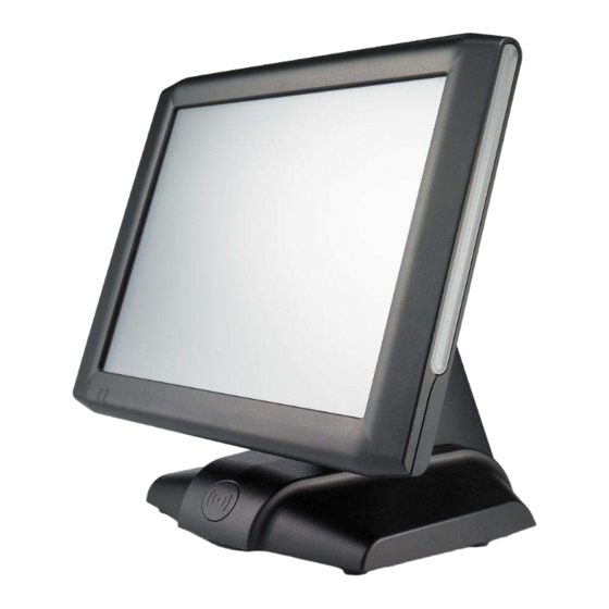
Page 9: A Quick Tour Of Gladius Smart
A Quick Tour of GLADIUS SMART Before you start, please take a moment to become familiar with GLADIUS SMART. Wireless Module Display Power LED VFD or Monitor pole stand Identification Devices Power Cable Back I/O Power Adapter... -
Page 10: Gladius Smart Dimension
GLADIUS SMART Dimension... -
Page 11: Rear I/O Panel (With Variety Types Of Second Io Board)
Rear I/O Panel (with variety types of Second IO board) COM5COM3 COM5COM3 COM5COM3 I/O Port Connector Type Description Power DC Power Connector Connects Gladius Smart to the power supply. The USB (Universal Serial Bus) port can be used to connect USB devices. The LAN port is used to hook Model H700 to a LAN RJ45 Connector local area network. -
Page 12: Packing List
COM4/COM5 COM4 is used for VFD, the rests are optional to RJ45 Connector connect to other devices /COM3(Optional) Power USB 12V 12V/24V power out support /24V(Optional) Line Out Earphone Connector The audio port is for speakers. Mic In(Optional) Microphone Connector This is used for allowing usage of microphone 26 PIN SCSI II The parallel port LPT1 can be used to connect... -
Page 13: How To Use This Manual
How to Use This Manual This manual contains all the information you need to set up and use Gladius Smart. In addition, you can also refer to the manuals for the operating system and added hardware. Chapter 1 Provides an introduction to Gladius Smart and this manual. Chapter 2 Provides all necessary information for all hardware setup. -
Page 14: Hardware Setup
GLADIUS SMART Assembly Please make sure that the system power is turned off and the power supply is disconnected when making any hardware changes to GLADIUS SMART. Access to jumper setting and RAM 1. Turn off system power 2. Remove four screws to detach the panel 3. -
Page 15: Change The Adapter Under The Terminal And Beware Of The Direction
3. Change the adapter under the terminal and beware of the direction 4. Fix with a iron kit and one screw 5. Link the DC power connector to terminal 2.5” Hard Disk Drive Installation 1. Turn off system power 2. Open the cover on the left of terminal and turn off system power 3. -
Page 16: Magnetic Card Reader Installation
Magnetic Card Reader Installation 1. Turn off system power. 2. The MCR socket can be found on the right side of terminal 3. Attach the MCR Assembly to terminal and connect the MCR cable to the MCR socket. 4. Lock MCR to terminal with 2 screws. Note: If the MCR does not work normally, please refer to troubleshooting... -
Page 17: Vfd Customer Display Installation
MCR Parameter Modification This option is for users who need to customize the MCR parameters for a particular task. The MCR parameters can be modified by using the supplied utility program. The utility can be found on the DVD that came with your system in the “\Utilities\USB MSR\Software”... -
Page 18: Cash Drawer Installation
Cash Drawer Installation Before connecting the cash drawer to the GLADIUS SMART, please make sure the drive voltage and cable pin assignment of the cash drawer matches the definition of the cash drawer port of GLADIUS SMART. For programmers, please refer to the folder “Utility” “Cash Drawer”... -
Page 19: Software Setup
Driver Download from FEC Website Model A: Please go to FEC website and download Gladius Smart(AL-7435) driver. B: The installation sequence: Chipset Driver -> VGA Driver -> LAN Driver -> Audio Driver - >Touch Driver ->Other Driver (optional) C: Then, you can start to install. Please follow this installation sequence accordingly. -
Page 20: Chipset Driver Installation
Chipset Driver Installation Intel ATOM D525 Chipset Installation Utilities for Windows XP Step 1. Please download the Intel chipset driver from website. Step 2. Click Next Step 3. Read the License Agreement and click Yes. -
Page 21: Vga Driver Installation
Step 4. Click Next and the drivers for the Intel Chip set will install. Step 5. Please wait while the setup program processing. Step 6. When the 'Setup COMPLETE' message appears click Finish to restart your computer. VGA Driver Installation... - Page 22 Step 1. Please download the VGA driver from website Step 2. Click Next and click Yes of License Agreement Page Note: When installing the IEGD driver for VGA under POSready 2009, the default setting is 800x600 with Clone mode; if you need to use Extension Mode, please set the 2 panel as primary as below.
-
Page 23: Lan Driver Installation
LAN Driver Installation Step 1. Please double confirm the LAN driver from website. Step 2. Click “Next” to continue Step 3. Click “Next” to continue Step 4. Click Next to continue Step 5. Click Finish to complete the installation procedure. -
Page 24: Audio Driver Installation
Audio Driver Installation Step 1. Please download the Audio driver from website. Step 2. Click “Next” to continue Step 3. Click Next to continue. -
Page 25: Elo Touch Installation
Step 4. Click Finish and restart the system. ELO Touch Installation Step 1. Please double confirm the ELO driver from website Step 2. Click “OK” to continue unzip the driver(for latest version, please reference to FEC website) - Page 26 Step 3. Install Elo Touch drivers and utilities. Step 4. Tick the Install Touchscreen Drivers and click Next to continue Step 5. Read the “License Agreement” and click Yes if you accept it.
- Page 27 Step 6. Select “Auto-detect Elo devices.” and click Next. Step 7. Click Calibrate Elo Touchscreen monitors...
-
Page 28: Elo Control Panel
Step 8 .Using a soft tip object such as finger to calibrate the touch screen (Red bull’s eye will pop up three time on different position) ELO Control Panel This section explains the different options in the ELO control Panel. General tab The General tab allows you to calibrate the touch screen with the Align button. - Page 29 Mode tab The Mode tab allows you to: Adjust all mouse emulation controls. Change cursor properties Enable or disable right mouse button utility. Sound tab The Sound tab allows you to: To change sound properties for ELO touch tools.
- Page 30 Properties tab The Properties tab allows you to: View Controller Information. About tab The About tab displays Information about ELO Touch systems...
-
Page 31: Eeti Touchkit Tools Installation
EETI TouchKit Tools Installation Step 1. Please double confirm the EETI driver downloaded from website Step 2. Click “OK” to continue unzip the driver Step 3. Open Setup.exe Step 4. Click Next Step 5. Click Next... - Page 32 Step 6. Click OK to close the pop-up dialog. Step 7. Click “Support Multi-Monitor System” and then Next to continue. Step 8. Click Next Step 9. Click OK and turn off the computer to restart your system again.
- Page 33 After the system finish rebooting follow the directions to calibrate the Touch screen.
-
Page 34: Touchkit Control Panel
TouchKit Control Panel This section explains the different options in the TouchKit control Panel. General tab The general tab allows you to: Manage the touch screen controller you installed. Tools tab The tools tab allows you to: Calibrate the touch screen with the 4 Points Calibration button. -
Page 35: Wireless Lan Driver Installation
GLADIUS SMART System manual version 1.4 Wireless LAN Driver Installation Step 1. Please double confirm the Wireless LAN driver from website. Step 2. Click “Next” to continue Step 3. Select Install driver and Ralink WLAN Utility Step 4. Select “Ralink Configuration Tool”Select “Optimize for WiFi mode”... - Page 36 GLADIUS SMART System manual version 1.4 Step 5. Select Install to continue Step 6. Select Finish to complete the installation...
-
Page 37: Specifications
GLADIUS SMART System manual version 1.4 Gladius Smart Specifications System Configuration Processor Intel D525 1.8GHz (Dual Core, L2 cache 1MB) Chipset D525+ICH8M Memory 1 x DDRIII 800MHz SO-DIMM (Up to 4GB) Size / Resolution 15" LED / 1024 x 768 / 100K hrs (Option: CCFL / 1024 x 768 / 30K hrs) Brightness 450 nits (Option:250 nits) Touch Screen... -
Page 38: I/O Pin Definition
GLADIUS SMART System manual version 1.4 Hard Disk Drive 1 x 2.5" SATA type Speaker Integrated 2W x 2 stereo speakers Power Supply 150W 12V External Power Adaptor Construction Whole Aluminum Housing Color / ID Black Optional LCM Use COM6 with 5V as default Thermal Conditions Fanless Thermal Design Operating... - Page 39 GLADIUS SMART System manual version 1.4 The definition of pin1 , pin 2 and pin4 are depending on jumper setting from JCOM4 and VFD_JR1 D. USB 2.0/1.1 Port COM4_USB1 USB_LAN1 Definition USB 5V E. COM2 Definition COM2 RI/ 5V /12V F.
- Page 40 GLADIUS SMART System manual version 1.4 Definition Data 0+ Connection/Speed LED: Data 0- State Description Data 1+ 1 Gbps Data 1- 1 00 Mbps Data 2+ Data 2- Data 3+ Activity LED: Data 3- State Description Transmitting USB_LAN1 H. LPT Port Definition Definition STB-...
-
Page 41: Jumper Setting
GLADIUS SMART System manual version 1.4 J. RJ11 Port RJ11 Definition GPIO-0 CASH Drawer Switch GPIO-1 K. AUDIO_JACK (Audio Line Out) Definition Audio Jack Line Out (L) AUDIO_JD -ACZ_DET Line Out (R) Jumper Setting... - Page 42 GLADIUS SMART System manual version 1.4 1. DC_OUT (12V for external/internal use, This connector is reserved for future use) DC 12V OUT: Definition 2. CPU_FAN (CPU FAN) 3. SYS_FAN (System FAN) CPU_FAN: SYS_FAN: Pin Definition Definition +12V/RPM +12V/RPM control control RPM detect RPM detect RPM control...
- Page 43 GLADIUS SMART System manual version 1.4 4. KB_MS2 (PS/2 Keyboard and PS/2 Mouse) KB_MS2: Definition KDAT F_KDAT KCLK F_KCLK 5. LVDS_PWR1 (LVDS 3V/5V selection) LVDS_PWR1: Default: 1-2 Definition 3.3V DC input 6. INV_BRIG1 (Inverter with Box-header ) INV_BRIG1: Definition 12V DC out 12V DC out Backlight Controller Backlight Enable...
- Page 44 GLADIUS SMART System manual version 1.4 Definition Definition Definition Backlight Enable LVDS Clock+ Backlight 5V EDID Data Backlight Controller Data1+ EDID Clock Data2- Data1- LVDS Power 3.3V Data2+ LVDS Power 3.3V Data0+ Backlight 5V LVDS Clock- Data0- Backlight 5V 8. JRS1, JRS2, JRS3, JRS4, JRS5 (Only COM2 available for RS232,RS422 or RS485 selections) Default 1-2 Definition...
- Page 45 GLADIUS SMART System manual version 1.4 9. JCOM1, JCOM2, JCOM3, JCOM4,JCOM5,JCOM6 for D-sub 9’s Pin 9 output 5V,12V or RI (COM4 output on RJ-45’s Pin1&2) Default 3-4 Short Definition 1-2 Short 3-4 Short 5-6 Short ***PS: JCOM4 is pre-set as 5-6 short for 12V customer display JCOM6 is pre-set as 1-2 short for 5v built-in LCM display 10.
- Page 46 GLADIUS SMART System manual version 1.4 VFD_JR1 (VFD & RS232 Mode select) Definition Definition CTS4- RTS4- Signal for PIN2 of COM4 port Signal for PIN4 of COM4 port RI4-/1_5V/12V_F ***PS: JCOM4 is set to 5-6 short for 12V VFD display as default. Definition VFD Mode VFD_JR1[1-2], [3-5], [4-6]...
- Page 47 GLADIUS SMART System manual version 1.4 12. JFRONT (Front Panel Connector with Box-header) Definition Definition Stand-by LED Power LED Power Switch# LAN Action LED Stand-by 5V HDD LED# VCC 5V System Reset# 13. F_USB1, F_USB2, (USB Pin-header) Definition Definition USB Power 5V USB Power 5V USB Dx- USB Dy-...
- Page 48 GLADIUS SMART System manual version 1.4 14. USB_PWR1, USB_PWR2, USB_PWR3 (Jumper for Stand-by ,5V or VCC 5V selections) Default 1-2 short Definition VCC 5V USB DC IN Stand-by 5V 15. F_AUDIO (Front Audio Box-header) Definition Definition Amplifier Out_R+ MIC_L Amplifier Out_R- MIC_R Line In_R Amplifier Out_L+...
- Page 49 GLADIUS SMART System manual version 1.4 17. CLR_COMS1 (Clear CMOS Pin-header) Default 2-3 short Definition Battery 3V Battery 3V 18. SATAPW_1, SATAPW_2 (SATA HDD Power 5V & 12V) Definition +12V 19. LCDPWR_CON (LCD Power ON/OFF) Default 1-2 Open Short 1-2 Open 1-2 20.
-
Page 50: Troubleshooting
GLADIUS SMART System manual version 1.4 Please note that the following troubleshooting guide is designed for people with strong computer hardware knowledge such as System Administrators and Engineers. Power is on, but there is no Panel Display A) Enter BIOS setup program and then get into the Boot Display option. Check if the default setting is [ Auto ];... -
Page 51: Second Lcd Panel Is Not Functioning Properly
GLADIUS SMART System manual version 1.4 controller, the touch panel may be not installed properly or it could be defective. Second LCD Panel is Not Functioning Properly Check that the VGA driver is installed properly (Please refer to the VGA driver installation section). -
Page 52: Lan Is Not Functioning Properly
GLADIUS SMART System manual version 1.4 Ensure that COM4 is enabled in the CMOS setup, and data is written to COM4 in the application. Check if there is any display when system power is ON, if the screen is blank, please follow the steps below.
Need help?
Do you have a question about the Gladius Smart FH-5251 and is the answer not in the manual?
Questions and answers