Table of Contents
Advertisement
U
s
e
U
s
e
MegaPOS Lite
Mega POS MP-3000 Series
MP-3435 / MP-3432
MP-3425 / MP-3422
15" /12" Fanless POS system
Copyright © 2012. All rights reserved.
All other brand names are registered trademarks of their respective owners.
r
'
s
M
a
r
'
s
M
a
(M/B: FH-5251/FH-4551)
Version 1.7
1
n
u
a
l
n
u
a
l
Advertisement
Table of Contents

Related Manuals for Firich Enterprise FH-5251


Summary of Contents for Firich Enterprise FH-5251
- Page 1 MegaPOS Lite (M/B: FH-5251/FH-4551) Mega POS MP-3000 Series MP-3435 / MP-3432 MP-3425 / MP-3422 15” /12” Fanless POS system Version 1.7 Copyright © 2012. All rights reserved. All other brand names are registered trademarks of their respective owners.
- Page 2 Firich Enterprise Co., Ltd. Information provided in this manual is intended to be accurate and reliable. However, Firich Enterprise Co., Ltd assumes no responsibility for its use, nor for any infringements upon the rights of third parties, which may result from its use.
- Page 3 Safety and Warranty 1. Read these safety instructions carefully. 2. Keep this user's manual for later reference. 3. Disconnect this equipment from any AC outlet before cleaning. Do not use liquid or spray detergents for cleaning. Use a damp cloth. 4.
-
Page 4: Table Of Contents
About this Manual ........................ 5 Introduction MegaPOS Lite (MP-3435 / MP-3432) Introduction ............... 1 A Quick Tour for MP-3435 ....................2 MP-3435 Dimension ......................3 Rear I/O Panel........................4 Packing List ......................... 5 Optional Devices:......................... 6 Hardware Installation and Upgrading 2.5”... -
Page 5: About This Manual
COM1, COM2, COM5 Are Not Functioning Properly ............44 Cash Drawer Port Is Not Functioning Properly..............44 USB Device Is Not Functioning Properly................44 About this Manual This manual contains all the information you need to set up and use MP-3435/3432. Chapter 1 Provides an introduction to MP-3435/3432 and this manual. -
Page 6: Introduction
ersion 0.3 MP-3435 / MP-3432 System manual v MegaPOS Lite (MP-3435 / MP-3432) Introduction To reach the balance of budget-saving and strong requirement for product quality, MegaPOS Lite is designed with quality-oriented and cost-effective concept. Fanless as it is, MP-3435 / MP- 3432 provide a decent choice for noise-free environment applications with optimized product reliability. -
Page 7: A Quick Tour For Mp-3435
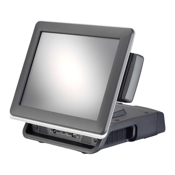
ersion 0.3 MP-3435 / MP-3432 System manual v A Quick Tour for MP-3435 Before you start, take a moment to become familiar with MP-3435. Display Identification Device System Venting Power Switch with LED HDD LED / LAN LED / USB Port Built-in Customer Antenna Display (LCM) -
Page 8: Mp-3435 Dimension
ersion 0.3 MP-3435 / MP-3432 System manual v MP-3435 Dimension... -
Page 9: Rear I/O Panel
ersion 0.3 MP-3435 / MP-3432 System manual v Rear I/O Panel I/O Port Connector Type Description Audio Jack Earphone connector Connect the speakers to this port USB type A Standard USB connector for external device connector DC IN DC-in connector Connect the power adaptor to this port +12V DC Out 12V DC-out... -
Page 10: Packing List
ersion 0.3 MP-3435 / MP-3432 System manual v Packing List • MP-3435 / MP-3432 Main System x 1 • Power Adaptor x 1 / AC Power Cord x 1 • COM port switching cable (RJ45 to D-SUB 9 pin) x 1... -
Page 11: Optional Devices
ersion 0.3 MP-3435 / MP-3432 System manual v Optional Devices: • Integrated LCM Display • Pole-type Customer Display • • WiFi Wireless Module... -
Page 12: Hardware Installation And Upgrading
ersion 0.3 MP-3435 / MP-3432 System manual v Do not remove the rear cover until you have verified that no power is supplied to the system. Power must be switched off and the power cord must be unplugged. Every time you service the system, you should be aware of this. -
Page 13: Pole-Type Vfd Installation
ersion 0.3 MP-3435 / MP-3432 System manual v 4. Place HDD kit on the door, 2.5” fasten it with 4 screws and connect with the SATA cable. SATA cable 5. Restore the maintenance door to the system. 6. Fix the door with the screw. 7. -
Page 14: Memory (Ddrii Ram) / Dom Installation
ersion 0.3 MP-3435 / MP-3432 System manual v Memory (DDRII RAM) / DOM Installation Unscrew and remove the top cover Install the DDRII RAM or DOM you require Before restore the top cover, please check the thermal pad stays Compact Flash Card (CF) Installation Unscrew and remove the maintenance door Install the CF you require... -
Page 15: Mcr Configuration Modification
ersion 0.3 MP-3435 / MP-3432 System manual v MCR Configuration Modification This option is for users who need to customize the MCR configurations for a particular task. To enter the Configuration Mode, please execute text editor program (such as Microsoft Word, Notepad…etc.) first, and then press [Ctrl] + [Alt] + [F10]. - Page 16 ersion 0.3 MP-3435 / MP-3432 System manual v Up to two cash drawers may be driven from this port. Driving voltage of the solenoid is DC+12V. I/O port 284 is used for drawer operation. A test program is supplied, for Linux and Windows, source code of which is available on request by software developers.
-
Page 17: Software Installation And Setup
ersion 0.3 MP-3435 / MP-3432 System manual v Driver Download from FEC Website Model A: Please go to FEC website and download the drivers. B: The installation sequence: Chipset Driver -> VGA Driver -> LAN Driver -> Audio Driver - >Touch Driver ->Other Driver (optional) C: Then, you can start to install. -
Page 18: Chipset Driver Installation
ersion 0.3 MP-3435 / MP-3432 System manual v Chipset Driver Installation Intel ATOM D525 Chipset Installation Utilities for Windows XP Step 1. Please download the Intel chipset driver from website. Step 2. Click Next Step 3. Read the License Agreement and click Yes. - Page 19 ersion 0.3 MP-3435 / MP-3432 System manual v Step 4. Click Next and the drivers for the Intel Chip set will install. Step 5. Please wait while the setup program processing. Step 6. When the 'Setup COMPLETE' message appears click Finish to restart your computer.
-
Page 20: Vga Driver Installation
ersion 0.3 MP-3435 / MP-3432 System manual v VGA Driver Installation Step 1. Please download the VGA driver from website Step 2. Click Next and click Yes of License Agreement Page Note: When installing the IEGD driver for VGA under POSready 2009, the default setting is 800x600 with Clone mode;... -
Page 21: Lan Driver Installation
ersion 0.3 MP-3435 / MP-3432 System manual v LAN Driver Installation Step 1. Please double confirm the LAN driver from website. Step 2. Click “Next” to continue Step 3. Click “Next” to continue Step 4. Click Next to continue Step 5. Click Finish to complete the installation procedure. -
Page 22: Audio Driver Installation
ersion 0.3 MP-3435 / MP-3432 System manual v Audio Driver Installation Step 1. Please download the Audio driver from website. Step 2. Click “Next” to continue Step 3. Click Next to continue. Step 4. Click Finish and restart the system. -
Page 23: Elo Touch Installation
ersion 0.3 MP-3435 / MP-3432 System manual v ELO Touch Installation Find the setup file through index(Tools) 2. Open SW601854_TETouch_5.4.2.exe (for latest version, please reference to FEC website) 3. Click OK to continue. 4. Click Unzip; Unzip the files successfully and click OK to continue the installation. - Page 24 ersion 0.3 MP-3435 / MP-3432 System manual v 5. Click Next to continue. 6. Choose Install Serial Touch Screen Driver and click Next to continue. 7. Read the “License Agreement” and click Yes and select Auto Detect ELO touchscreens and click Next...
- Page 25 ersion 0.3 MP-3435 / MP-3432 System manual v 8. Select COM3 and click Next for further installation steps. 9. Setup complete and execute Calibrate Elo Touch Screen Monitors and Click Finish. 10. Start calibrating the touchscreen by touch the targets showed on the screen.
- Page 26 ersion 0.3 MP-3435 / MP-3432 System manual v 11. According to ELO Touch Screen Properties; Make sure the COM port listed is COM3 for your touch monitor; adjust a proper sound of touch buzzer Press Next to continue.
-
Page 27: Elo Control Panel
ersion 0.3 MP-3435 / MP-3432 System manual v 12. If the cursor is working fine, click to finish the setting; if not, click to calibrate the screen again. IT MAY BE NECESSARY TO RESTART YOUR COMPUTER TO UTILIZE YOUR TOUCHSCREEN FEATURES. 13. - Page 28 ersion 0.3 MP-3435 / MP-3432 System manual v Mode tab The Buttons tab allows you to: • Adjust all mouse emulation controls. • Change cursor properties • Enable or disable right mouse button utility. Sound tab The Sound tab allows you to: •...
-
Page 29: Eeti Touchkit Tools Installation
ersion 0.3 MP-3435 / MP-3432 System manual v • View Controller Information. About tab The About tab displays Information about ELO Touch systems EETI TouchKit Tools Installation Step 1. Please double confirm the EETI driver downloaded from website Step 2. Click “OK” to continue unzip the driver Step 3. - Page 30 ersion 0.3 MP-3435 / MP-3432 System manual v Step 4. Click Next Step 5. Click Next...
- Page 31 ersion 0.3 MP-3435 / MP-3432 System manual v Step 6. Click OK to close the pop-up dialog. Step 7. Click “Support Multi-Monitor System” and then Next to continue. Step 8. Click Next...
- Page 32 ersion 0.3 MP-3435 / MP-3432 System manual v Step 9. Click OK and turn off the computer to restart your system again. After the system finish rebooting follow the directions to calibrate the Touch screen.
-
Page 33: Touchkit Control Panel
ersion 0.3 MP-3435 / MP-3432 System manual v TouchKit Control Panel This section explains the different options in the TouchKit control Panel. General tab The general tab allows you to: • Manage the touch screen controller you installed. Tools tab The tools tab allows you to: •... -
Page 34: Wireless Lan Driver Installation
ersion 0.3 MP-3435 / MP-3432 System manual v Wireless LAN Driver Installation Step 1. Please double confirm the Wireless LAN driver from website. Step 2. Click “Next” to continue Step 3. Select Install driver and Ralink WLAN Utility Step 4. Select “Ralink Configuration Tool”Select “Optimize for WiFi mode”... - Page 35 ersion 0.3 MP-3435 / MP-3432 System manual v Step 5. Select Install to continue Step 6. Select Finish to complete the installation...
-
Page 36: Specifications
ersion 0.3 MP-3435 / MP-3432 System manual v MP-3435 Specifications System Configuration CPU (On Board) INTEL ATOM D525 (1.8GHz with 1M L2 cache) Chipset ICH8M 1 x 204pin DDR3 up to 4GB memory Memory VGA controller GMA3150 LCD Panel 15” TFT LCD Panel (1024x768). Touch Panel 15”... -
Page 37: I/O Pin Definition
ersion 0.3 MP-3435 / MP-3432 System manual v 20 – 30W Power Consumption (Standard system while running programs and accessing HDD). Operating temperature 0 ℃ ~ 40 ℃ Operating Temperature I/O Pin Definition A. DC_IN (DC Adapter 12V in) DC_IN Definition B. - Page 38 ersion 0.3 MP-3435 / MP-3432 System manual v Definition USB 5V E. COM2 Definition COM2 RI/ 5V /12V F. VGA Definition GREEN BLUE VCC 5V DDC Data H-SYNC V-SYNC DDC Clock G. USB_LAN1 (LAN connector RJ45+USB 2.0/1.1 Port)
- Page 39 ersion 0.3 MP-3435 / MP-3432 System manual v Definition Data 0+ Connection/Speed LED: Data 0- State Description Data 1+ 1 Gbps Data 1- 1 00 Mbps Data 2+ Data 2- Data 3+ Activity LED: Data 3- State Description Transmitting USB_LAN1 H.
- Page 40 ersion 0.3 MP-3435 / MP-3432 System manual v I. KB_MS1 (PS/2 Connector) Definition Keyboard Data Mouse Data Mouse Clock Keyboard Clock J. RJ11 Port RJ11 Definition GPIO-0 CASH Drawer Switch GPIO-1 K. AUDIO_JACK (Audio Line Out) Definition Audio Jack Line Out (L) AUDIO_JD -ACZ_DET Line Out (R)
-
Page 41: Jumper Setting
ersion 0.3 MP-3435 / MP-3432 System manual v Jumper Setting 1. DC_OUT (12V for external/internal use, This connector is reserved for future use) DC 12V OUT: Definition 2. CPU_FAN (CPU FAN) 3. SYS_FAN (System FAN) CPU_FAN: SYS_FAN: Pin Definition Definition +12V/RPM +12V/RPM control control... - Page 42 ersion 0.3 MP-3435 / MP-3432 System manual v 4. KB_MS2 (PS/2 Keyboard and PS/2 Mouse) KB_MS2: Definition KDAT F_KDAT KCLK F_KCLK 5. LVDS_PWR1 (LVDS 3V/5V selection) LVDS_PWR1: Default: 1-2 Definition 3.3V DC input 6. INV_BRIG1 (Inverter with Box-header ) INV_BRIG1: Definition 12V DC out 12V DC out...
- Page 43 ersion 0.3 MP-3435 / MP-3432 System manual v 8. JRS1, JRS2, JRS3, JRS4, JRS5 (Only COM2 available for RS232,RS422 or RS485 selections) Default 1-2 Definition RS232 UART RXD RS422 UART RXD RS485 UART RXD JRS2, JRS3, JRS4, JRS5 JRS2: Default 2-3 short JRS3: Default 2-3short Definition Definition...
- Page 44 ersion 0.3 MP-3435 / MP-3432 System manual v Definition Definition RI/+5V/+12V RI/+5V/+12V VFD_JR1 (VFD & RS232 Mode select) Definition Definition CTS4- RTS4- Signal for PIN2 of COM4 port Signal for PIN4 of COM4 port RI4-/1_5V/12V_F ***PS: JCOM4 is set to 5-6 short for 12V VFD display as default. Definition VFD Mode VFD_JR1[1-2], [3-5], [4-6] Short...
- Page 45 ersion 0.3 MP-3435 / MP-3432 System manual v 12. JFRONT (Front Panel Connector with Box-header) Definition Definition Stand-by LED Power LED Power Switch# LAN Action LED Stand-by 5V HDD LED# VCC 5V System Reset# 13. F_USB1, F_USB2, (USB Pin-header) Definition Definition USB Power 5V USB Power 5V...
- Page 46 ersion 0.3 MP-3435 / MP-3432 System manual v 14. USB_PWR1, USB_PWR2, USB_PWR3 (Jumper for Stand-by ,5V or VCC 5V selections) Default 1-2 short Definition VCC 5V USB DC IN Stand-by 5V 15. F_AUDIO (Front Audio Box-header) Definition Definition Amplifier Out_R+ MIC_L Amplifier Out_R- MIC_R...
- Page 47 ersion 0.3 MP-3435 / MP-3432 System manual v 17. CLR_COMS1 (Clear CMOS Pin-header) Default 2-3 short Definition Battery 3V Battery 3V 18. SATAPW_1, SATAPW_2 (SATA HDD Power 5V & 12V) Definition +12V 19. LCDPWR_CON (LCD Power ON/OFF) Default 1-2 Open Short 1-2 Open 1-2 20.
-
Page 48: Troubleshooting
ersion 0.3 MP-3435 / MP-3432 System manual v Please note that the following troubleshooting guide is designed for people with strong computer hardware knowledge such as System Administrators and Engineers. Touch Panel Does Not Work Check CMOS settings, COM3 needs to be “Enabled”. Check if there are no conflicts between COM3 and any other devices. -
Page 49: Ps/2 Keyboard Is Not Functioning Normally
ersion 0.3 MP-3435 / MP-3432 System manual v PS/2 Keyboard Is Not Functioning Normally Make sure the keyboard is properly connected to the PS/2 keyboard port before the system is powered up. If the keyboard is connected after Windows2000 has been booted, the keyboard will not work.
Need help?
Do you have a question about the FH-5251 and is the answer not in the manual?
Questions and answers