Table of Contents
Advertisement
Member of:
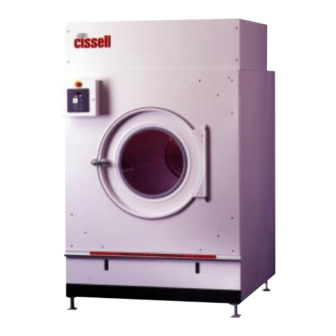
OWNER'S MANUAL
175 Lb. Laundry Dryer
MODELS
GAS
STEAM
HD175G
HD175S
CISSELL MANUFACTURING COMPANY
HEADQUARTERS
PHONE: (502) 587-1292
831 SOUTH FIRST ST.
SALES FAX: (502) 585-3625
P.O. BOX 32270
SERVICE/PARTS FAX: (502) 681-1275
LOUISVILLE, KY 40232-2270
THIS MANUAL MUST BE GIVEN TO THE EQUIPMENT OWNER.
MAN2175
(ECN5530)
8/99
Page 1
Advertisement
Table of Contents
Troubleshooting

Related Manuals for Cissell HD175G


Summary of Contents for Cissell HD175G
-
Page 1: Model Numbers & Company Address
Member of: OWNER'S MANUAL 175 Lb. Laundry Dryer MODELS STEAM HD175G HD175S CISSELL MANUFACTURING COMPANY HEADQUARTERS PHONE: (502) 587-1292 831 SOUTH FIRST ST. SALES FAX: (502) 585-3625 P.O. BOX 32270 SERVICE/PARTS FAX: (502) 681-1275 LOUISVILLE, KY 40232-2270 THIS MANUAL MUST BE GIVEN TO THE EQUIPMENT OWNER. -
Page 2: Important Notices
IMPORTANT NOTICES—PLEASE READ For optimum efficiency and safety, we recommend that you read the manual before operating the equipment. Store this manual in a file or binder and keep for future reference. WARNING: For your safety, the information in this manual must be followed to minimize the risk of fire or explosion or to prevent property damage, personal injury or loss of life. - Page 3 WARNING: To avoid fire hazard, do not dry articles containing foam rubber or similar texture materials. Do not put into this dryer flammable items such as baby bed mattresses, throw rugs,undergarments (brassieres, etc.) and other items which use rubber as padding or backing. Rubber easily oxidizes causing excessive heat and possible fire.
- Page 4 ATTENTION: L’ACHETEUR DOIT PLACER L’AVERTISSEMENT SUIVANT DANS UN ENDROIT CLAIR ET VISIBLE: AVERTISSEMENT. Assurez-vous de bien suivre les instructions donnees dans cette notice pour reduire au minimum le risque d’incendie ou d’explosion ou pour eviter tuot dommage materiel, toute blessure ou la mort. __ Ne pas entreposer ni utiliser d’essence ni d’autres vapeurs ou liquides inflammables dans le voisinage de cet appareil ou de tout autre...
-
Page 5: Dryer Warranty
Cissell’s factory, transportation prepaid, within the applicable warranty period and found by Cissell to have been defective, and in no event shall Cissell be liable for damages of any kind, whether for any injury to persons or property or for any special or consequential damages. -
Page 6: Table Of Contents
TABLE OF CONTENTS 175 LB. LAUNDRY DRYER PAGE Model Numbers & Company Address................. 1 Important Notices ......................2-4 Dryer Warranty ........................5 Table of Contents ........................ 6 Warnings, Cautionary Notes and Symbols................ 7-8 Unpacking and General Installation ................9-10 Dryer Specifications ....................11-17 Main Drive Motor List ...................... -
Page 7: Warnings, Cautionary Notes And Symbols
SYMBOLS The following symbols are used in this manual and/or on the machine. Symbol Description NOTE! Hot! Do Not Touch Heib! Nicht Beruhren Haute temperature! Ne pas toucher Caliente! no tocar Heet! Niet Aanraken dangerous voltage tension dangereuse Gafahrliche elektrische Spannung tension peligrosa marche conectado... - Page 8 SYMBOLS The following symbols are used in this manual and/or on the machine. Symbol Description rotation in two directions rotation dans les deux sens Drehbewigung in zwei Richtungen movimiento rotativo en los dos sentidos direction of rotation sens de mouvement continu de rotation Drehbewegung in Pfeilrichtung movimiento giratorio o rotatorio en el sentido de la flecha...
-
Page 9: Unpacking And General Installation
Unpacking/General Installation (All Dryers) This dryer is packed in a large (heavy-duty) protective wooden crate. UNPACKING Upon arrival of the equipment, any damage in shipment should be reported to the carrier immediately. Upon determining permanent location of a unit, care should be taken in movement and placement of equipment. - Page 10 General Installation (All Dryers) GENERAL Position dryer for the least amount of exhaust piping and elbows, INSTALLATION and allow free access to the rear of dryer for future servicing of (ALL DRYERS) belts, pulleys and motors. Installation clearance from all combustable material for gas dryers is 24”...
-
Page 11: Dryer Specifications
175 LB. GAS DRYER SPECIFICATIONS (ILLUSTRATION) REAR VIEW ALL DIMENSIONS ARE +/- 1/4” (6.4 MM) AND ARE SUBJECT TO CHANGE WITHOUT NO- TICE Page 11... - Page 12 175 LB GAS DRYER SPECIFICATIONS (ILLUSTRATION) TOP VIEW DIMENSIONS REAR VIEW DIMENSIONS REAR COVER NOT SHOWN ALL DIMENSIONS ARE +/- 1/4” (6.4 MM) AND ARE SUBJECT TO CHANGE WITHOUT NO- TICE Page 12...
- Page 13 175 LB. STEAM DRYER SPECIFICATIONS (ILLUSTRATION) REAR VIEW ALL DIMENSIONS ARE +/- 1/4” (6.4 MM) AND ARE SUBJECT TO CHANGE WITHOUT NO- TICE Page 13...
- Page 14 175 LB. STEAM DRYER SPECIFICATIONS (ILLUSTRATION) TOP VIEW DIMENSIONS REAR VIEW DIMENSIONS REAR COVER NOT SHOWN ALL DIMENSIONS ARE +/- 1/4” (6.4 MM) AND ARE SUBJECT TO CHANGE WITHOUT NO- TICE Page 14...
- Page 15 Specifications for 175 lb. Gas Heated Dryer Basket Capacity .........175 lb (79 kg) Dryweight GENERAL SPECIFICATIONS FOR Electrical Specifications ......208-240/60/3, 480/60/3, 175 lb. GAS HEATED 220-380/50/3 DRYERS Motor Size: Basket ........2 Hp (1.49 kW) Motor Size: Fan ........5 Hp (3.73 kW) Floor Space ..........89”...
- Page 16 Specifications for 175 lb. Steam Heated Dryer Basket Capacity .........175 lb (79 kg) GENERAL SPECIFICATIONS FOR Electrical Specifications ......208-240/60/3, 480/60/3, 175 lb. STEAM HEATED 220-380/50/3 DRYERS Motor Size: Basket ........2 Hp (1.49 kW) Motor Size: Fan ........5 Hp (3.73 kW) Floor Space ..........89”...
-
Page 17: Dryer Specifications
175 lb. Steam Heated Laundry Dryers - Specifications ELECTRICAL Dryers must be electrically grounded by a separate #14 or larger CONNECTIONS green wire from the grounding terminal within the service connection (ALL DRYERS) box to a cold water pipe. In all cases, the grounding method must comply with local electrical code requirements;... -
Page 18: Main Drive Motor List
Main Drive Motors Motor No. Voltage Phase Amps MTR290 208/240 6.2 - 6.0 1725 Basket MTR290 1725 Basket MTR296 4.2 - 4.6 1725 Basket MTR292 220/380 6.4/3.7 1425 Basket MTR292 240/415 6.4/3.7 1425 Basket MTR309 208/240 13.0 3450 MTR291 1725 MTR298 1425 MTR298... -
Page 19: Gas Pipe Size Chart
Gas Pipe Size Chart TOTAL BTU/HR GAS PIPE SIZE FOR 1000 BTU (250 KCAL) NATURAL GAS (for LP Gas correct AT 7” (17.8 CM) W.C. PRESSURE TOTAL total BTU/HR below by KCAL multiplying by .6) In figuring total length of pipe, make allowance for tees and elbows. HOUR (25 ft.) (50 ft.) -
Page 20: Gas Piping Installation
Gas Piping Installation (Illustration) Page 20... -
Page 21: Gas Piping Installation
Gas Piping Installation 1. Gas service installation must conform with local codes, or in GAS PIPING the absence of local codes with the National Fuel Gas Code, INSTALLATION ANSI Z223.1 or the CAN/CGA-B149, Installation Codes. 2. Check rating plate located on rear wall of dryer, for type of gas to equip the dryer and the altitude (elevation). -
Page 22: Steam Piping Installation
Steam Piping Installation (Illustration) INDIVIDUALLY TRAPPED COILS ARE RECOMMENDED RATHER THAN MANFOLDING RETURN INTO ONE TRAP. Page 22... -
Page 23: Steam Piping Installation
Steam Piping - Installation Instructions 1. Set and anchor dryer in position. Machine should be level to assure STEAM PIPING INSTALLATION proper steam circulation. INSTRUCTIONS 2. To prevent condensate draining from headers to dryer, piping should have a minimum 12” above respective header. Do not make steam connection to header with a horizontal or downwardly facing tee or elbow. -
Page 24: Dryer Installation With Multiple Exhaust
Dryer Installation with Multiple Exhaust (Illustration) Page 24... -
Page 25: Dryer Installation With Multiple Exhaust
Dryer Installation with Multiple Exhaust For Exhaust Duct more than 14 feet and 2 elbows equivalent and more DRYER INSTALLATION than 0.6 inches static pressure. WITH MULTIPLE (See illustration on previous page.) EXHAUST 1. Make-up air from outside building may enter enclosure from top or side walls. - Page 26 Dryer Installation with Multiple Exhaust For Exhaust Duct less than 14 feet and 2 elbows equivalent and less than 0.6 inches static pressure. DRYER EXHAUSTS Area of section "A-A" must be equal to the sum of dryer exhaust pipes entering muliple exhaust pipe. (See chart below.) MODELS: L28FD30, L28US30, L36FD30, L36UR30, L36CD36, L44FD42 No.
-
Page 27: Dryer Installation With Separate Exhaust
Dryer Installation With Separate Exhaust (Preferred) For ductwork less than 14 feet and 2 elbows equivalent and less than 0.6 DRYER INSTALLATION inches static pressure. WITH SEPARATE EXHAUST (PREFERRED) NEVER exhaust the dryer into a chimney. NEVER install wire mesh screen over the exhaust or makeup air area. -
Page 28: Exhaust And Venting
Exhaust and Venting Nothing is more important than air flow for the proper operation of a DRYER AIR FLOW clothes dryer. A dryer is a pump which draws make-up air from the out-of- INSTALLATION doors, through the heater, through the clothes and then forces the air through the exhaust duct back to the out-of-doors. -
Page 29: Link Belts
Link Belts The Fan Assembly is rated at 0.6” W.C. back pressure. - Link Belts are adjustable for belt length. Please take links out to tighten fan belt. This may need to be done after dryer has been running for several days. If fan seems to be vibrating excessively, this may be an indication that the fan belt needs to be tightened. -
Page 30: Rules For Safe Operation Of Your Dryer
Rules for Safe Operation of Your Dryer RULES RULES FOR SAFE OPERATION OF YOUR 1. Be sure your dryer is installed properly in accordance with DRYER the recommended instructions. 2. CAUTION Be safe - Shut main electrical power supply and gas supply off externally before attempting service. -
Page 31: Rules For Safe Operation Of Your Dryer
Rules for Safe Operation of Your Dryer CAUTION Synthetic solvent fumes from dry cleaning machines create acids when drawn through the dryer. These acid fumes cause rusting of painted parts, pitting of bright plated parts and completely removes the zinc from galvanized metal parts, such as the tumbler basket. -
Page 32: Service Savers
Service Savers To help you troubleshoot the dryer, we list below the most TROUBLESHOOTING common reasons for service calls and some answers to the problems. Before you call service, please review the following items: DRYER WON’T START DRYER WON'T START 1. -
Page 33: Troubleshooting Charts
Troubleshooting Chart TROUBLE CAUSE REMEDY Basket motor runs, but V-Belt broken. Replace V-Belt. basket will not revolve. V-Belt loose. Adjust belt tension. Motor Pulley loose. Tighten Set Screw. Basket overloaded. Remove load. Not leveled. Check manual for proper leveling procedures. Dryer noisy or vibrating. -
Page 34: Troubleshooting Chart
Troubleshooting Chart TROUBLE CAUSE REMEDY Dryer runs, but no heat Line fuse or heater circuit fuse Replace fuse. (continued). blown to unit. Defective door switch. Check continuity across contacts, opened & closed. If defective, replace door switch. Air switch not operating. Clean out lint compartment daily. - Page 35 Troubleshooting Chart TROUBLE CAUSE REMEDY Dryer runs, but no heat Defective thermostat. Check continuity across thermostat. (continued). Limiting or safety thermostats are normally closed. If open, replace thermostat. Defective safety overload thermo- See above. stat. Lint compartment drawer open. Close drawer. Main burners Dirt in burner.
- Page 36 Troubleshooting Chart TROUBLE CAUSE REMEDY Motor will not start. No power. Check fuses on circuit breakers. Make sure main control switch is ON. Incorrect power. Check power source: voltage, phase, and frequency must be the same as specified on electrical rating plate.
-
Page 37: Troubleshooting Charts
Troubleshooting Chart TROUBLE CAUSE REMEDY Defective timer. Replace timer. Dryer does not stop at end of time period (6). Valve closed. Check all valves in steam supply and return Dryer runs no steam to -- make sure they are open. coils. -
Page 38: Direct Spark Ignition Operation
Direct-Spark Ignition Operation DIRECT SPARK NOTE: Some models are equipped with a dual ignition system. The dual ignition system contains two direct spark IGNITION ignition modules in parallel. Each module has its own OPERATION flame sense circuit and acts independently of the other. If either bonnet limit thermostat opens because of high heat or flame impingement, the entire ignition system will shut down. -
Page 39: Direct Spark Ignition Operation
DIRECT SPARK IGNITION OPERATION FLOW CHART The DSI module is powered by a 24 volts AC suppled by a step-down transformer in series with eight safety interlocks: A. Timer switching device (1) B. Main door and lint door switches (2) C. -
Page 40: General Maintenance
Maintenance—General MAINTENANCE MAINTENANCE 1. CLEAN LINT SCREEN DAILY. Remove lint before starting day’s operation. A clean lint screen will increase the efficiency of the dryer, as the moisture-laden air will be exhausted more quickly. 2. CLEAN BASKET AND SWEEPSHEETS. Clean periodically and/or as often as required. -
Page 41: General Maintenance
Maintenance—General MAINTENANCE (continued) MAINTENANCE 6. GAS BURNERS. Keep burners clean. Check and clean often. 7. GAS PRESSURE. Gas pressure should be checked periodically per specifications on separate page. 8. EXHAUST SYSTEM. Periodically check and clean. VOLTAGE. Voltage should be checked periodically per rating plate located on rear wall of dryer. - Page 42 BASKET ALIGNMENT Jacket Rear View BASKET TOO LOW If there are shims under Bearing B; 1. Loosen bolts 2. Remove shim(s). 3. Tighten bolts - check alignment. If there are no shims under B; 1. Loosen bolts on bearing A. 2.
-
Page 43: Shimming The Basket And Spider Assembly
Shimming the Basket and Spider Assembly (Illustration) Page 43... -
Page 44: Shimming The Basket And Spider Assembly
Shimming the Basket and Spider Assembly INSTRUCTIONS FOR This procedure is normally necessary when replacing either the basket or the spider assembly on any dryer. The alignment of these SHIMMING THE two parts is crucial in assuring a true running basket. BASKET AND SPIDER ASSEMBLY A. -
Page 45: Air Switch Adjustment
Air Switch Adjustment 1. Shut off current; disconnect leads and remove air switch. AIR SWITCH ADJUSTMENT 2. Lay air switch assembly on flat surface. Adjust air blade at “A” (figure 1) so that air blade lays flat and surface “B” is parallel to the flat surface. -
Page 46: Pulley And Belt Maintenance
Pulley and Belt Maintenance DRIVE PULLEYS DRIVE PULLEYS AND BELTS AND BELTS Before placing the dryer into operation, ensure that the drive belts and pulleys are in good condition and have sufficient belt tension. Check belt tension after dryer is in operation 2-3 weeks. Tighten as necessary. -
Page 47: Front Of Dryer - Parts
175 LB LAUNDRY DRYER (FRONT EXPLODED VIEW) EA-11621-0 LINT DOOR SWITCH TU14490 FRONT VALANCE ESA-00961-0 SWITCH ASSEMBLY TU14537 LINT DOOR ASM. IB140 3/8 FLAT WASHER TU14542 DMP CONTROL ASM. TU14340 JACKET WELDED ASM. TU3246 3/8-16 SCREW TU14360 FRONT PANEL ASM. TU6854 #14 S.M. -
Page 48: Rear Of Dryer - Parts
175 LB LAUNDRY DRYER (REAR EXPLODED VIEW) - Page 49 PARTS - 175 LB LAUNDRY DRYER (REAR) C249 NUT, HEX 5/16-18 27 TUX308 PLATE, IDLER W/A FB124 SCREW, H H 5/16-18 X 1” 28 TUX310 MTR PLATE W/A IB140 WASHER, FLAT 3/8" 29 TUX327 BOLT, H H. 5/8-11X2 1/2"LG TU14372 BRG, 2 1/2"...
-
Page 50: Front Panel And Door Assembly
TU14360 - FRONT PANEL ASSEMBLY EA-00652-0 REED SWITCH TU3209 #14 PAN HD. SCREW EA-00827-0 REED SWITCH HOUSING TU3212 5/16 LOCK WASHER PIF172 HINGE POST BEARING TU3785 #8 E.T. CUP WASHER TU14359 FRONT PANEL TU5503 DOOR LATCH SPACER TU14467 LOADING DOOR TU7169 GASKET TU2236... -
Page 51: Lint Door Assembly
LINT DOOR ASSEMBLY LA-00124-0 LATCH SB-00836-0 PANCAKE SCREW SB-00949-0 FASTENER TU14357 LINT DR. W/A TU14529 HANDLE TU14530 BUMPER TU14594 LABEL, CLEAN DAILY TU14640 TRIM, KICKPLATE Page 51... -
Page 52: Dmp Control Assembly
PARTS - TU14542 DMP CONTROL ASSEMBLY FB187 #10 LOCKWASHER M270 #6 LOCKWASHER P104 1/4" BRASS WASHER TU13621 CTRL. BOX TU14404 DMP CONTROL TU14405 OVERLAY TU14435 EMERGENCY STOP TU14469 DMP PANEL TU14470 DMP CTRL. PNL. TU2842 #10-32 HEX NUT TU3209 #14 S.M. SCREW TU3400 #6-32 NUT TU3479... -
Page 53: Fan Assembly
TU14481 - FAN MOTOR ASSEMBLY C249 NUT, 5/16-18 TU3246 SCREW, 3/8-16 H.H. IB140 WASHER, 3/8" FLAT TU4706 PLATE, MTR. MOUNT MTR* SEE MOTOR CHART TU4787 NUT, 3/8-16 HEX OP380 SCREW, 3/8-16 H.H. TU5439 SCREW, 5/16-18 H.H. TU14336 MTR. MTG TU6723 BUSHING, 1 1/8"... -
Page 54: Basket/Spider Assembly
TU14430 - BASKET/SPIDER ASSEMBLY TU10686 1/2-13 HEX NUT TU14326 ASM, BASKET TU14344 175# SPIDER ASM. TU2831 1/2 LOCKWASHER TUX285 1/2-13 SCREW Page 54... -
Page 55: Reversing Control Panel Assembly
TU14765 - REVERSING CONTROL PANEL ASSEMBLY CB36 SCREW, 1/4-20 EA-00673 MTR. CONTACTOR EA-00685 REV. CONTACTOR TU13480 TRANSFORMER TU14706 REV. OVERLOAD TU14707 MTR. OVERLOAD TU7733 #8 SELF DRILL SCR. TUX195 CTRL. BOX COVER TUX197 MTG. PLATE Page 55... -
Page 56: Gas Bonnet Assembly
TU14429 - 24V GAS BONNET ASSEMBLY 39060412 3/4 x 3/4 x 1-1/4 TEE TU4600 3/4" UNION CB36 1/4-20 x 1/2 SCR. TU4602 3/4"-90 STREET ELL. GA-00764-0 ELECTRODE TU4605 3/4"-90 ELL. TU13678 THERMOSTAT TU4608 3/4" x 2" NIPPLE TU13695 T-STAT MTG. BRKT. TU4934 1/4-20 H.H. -
Page 57: Steam Bonnet Assembly
TU14398 - 24V STEAM BONNET ASSEMBLY CB36 SCREW, 1/4-20 x 1/2 TU4600 UNION, 3/4 TU13517 VALVE, 3/4 STEAM TU4605 ELL, 3/4 90 DEG. TU14397 ASM, BON. WELD TU4608 NIPPLE, 3/4 x 2” LG. TU1699 COIL, 6 x 10 STEAM TU4610 NIPPLE, 3/4 x 5”... -
Page 58: Air Switch Assembly
TU8206 - AIR SWICTH ASSEMBLY F888 E-RING TU1770 INSULATOR TU1771 #6 TINNERMAN NUT TU2463 ACTUATOR ARM TU3219 #6 x 1 S.M.S. TU3476 DECAL TU7733 #8 x 1/2 S.M.S. TU8155 MICRO SWITCH TU8171 BRACKET ASM. Page 58... -
Page 59: Orifice Information
NOTE: Specifications (propane) For conversion from natural gas to Propane—1.53 specific gravity propane gas. Calorific value—2,500 Btu/cu. ft. 1. Order: 6 each—TU3539 orifice with Gas Input—87,500 Btu/hour per no. 34 drill size. burner total 2 each—K555 natural gas to LP gas conversion kit and follow directions. - Page 60 Table for Ordering Overload Heaters for Overload Relays OVERLOAD HEATER TABLE Motor Full Load Amps (FLA) SF = 1.15 OR GREATER SF = 1.00 Heater Size 40 Deg. C 60 Deg. C 40 Deg. C 60 Deg. C Amb. Amb. or more Amb.
-
Page 61: Ordering Overload Heaters For Overload Relays
Ordering Overload Heaters for Overload Relays ORDERING Properly sized overload heaters provide motor protection for the OVERLOAD HEATERS dryer. Improper heater size may allow the motor to be damaged, or FOR OVERLOAD could cause nuisance tripping. RELAYS Heater sizes are listed on the overload heater table on page 61. To use the table, refer to the motor rating plate and locate the full load amps (FLA), the service factor (SF), and the ambient temperature (Amb.). -
Page 62: Minimum Dryer Make-Up Air Requirements
Suggested Minimum Dryer Make-up Air Requirements Dryer Dryer Pocket Maximum Air Flow Duct Size For Required Make-up Model Capacity Rate per Pocket Service Connection Air Area per Pocket m3/h inch sq. inch cm2 C 30 ST 13.6 C 75 ST 1000 1700 1240... - Page 63 Page 63...
Need help?
Do you have a question about the HD175G and is the answer not in the manual?
Questions and answers