Table of Contents
Advertisement
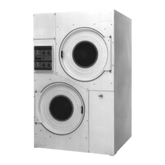
OWNER'S MANUAL
75 lb. HD STACK LAUNDRY DRYER
Gas: Natural and LP
Steam
Cissell Manufacturing Co.
HD75ST
831 S. First St. - P.O.Box 32270 - Louisville, Ky. - 40232-2270
Tel: (502) 587-1292 - Fax: (502) 585-2333 -
Sales Fax: (502) 585-3625 - Service/Parts Fax: (502) 681-1275
THIS MANUAL MUST BE GIVEN TO THE EQUIPMENT OWNER
Page 1
MANHD75ST
05/02
Advertisement
Table of Contents
Troubleshooting

Related Manuals for Cissell MANHD75ST


Summary of Contents for Cissell MANHD75ST
-
Page 1: Model Numbers & Company Address
OWNER'S MANUAL 75 lb. HD STACK LAUNDRY DRYER Gas: Natural and LP Steam Cissell Manufacturing Co. HD75ST 831 S. First St. - P.O.Box 32270 - Louisville, Ky. - 40232-2270 Tel: (502) 587-1292 - Fax: (502) 585-2333 - Sales Fax: (502) 585-3625 - Service/Parts Fax: (502) 681-1275... -
Page 2: Important Notices
IMPORTANT NOTICES—PLEASE READ For optimum efficiency and safety, we recommend that you read the manual before operating the equipment. Store this manual in a file or binder and keep for future reference. WARNING: For your safety, the information in this manual must be followed to minimize the risk of fire or explosion or to prevent property damage, personal injury or loss of life. - Page 3 WARNING: To avoid fire hazard, do not dry articles containing foam rubber or similar texture materials. Do not put into this dryer flammable items such as baby bed mattresses, throw rugs,undergarments (brassieres, etc.) and other items which use rubber as padding or backing. Rubber easily oxidizes causing excessive heat and possible fire.
- Page 4 ATTENTION: L’ACHETEUR DOIT PLACER L’AVERTISSEMENT SUIVANT DANS UN ENDROIT CLAIR ET VISIBLE: AVERTISSEMENT. Assurez-vous de bien suivre les instructions donnees dans cette notice pour reduire au minimum le risque d’incendie ou d’explosion ou pour eviter tuot dommage materiel, toute blessure ou la mort. __ Ne pas entreposer ni utiliser d’essence ni d’autres vapeurs ou liquides inflammables dans le voisinage de cet appareil ou de tout autre...
-
Page 5: Dryer Warranty
Cissell’s factory, transportation prepaid, within the applicable warranty period and found by Cissell to have been defective, and in no event shall Cissell be liable for damages of any kind, whether for any injury to persons or property or for any special or consequential damages. -
Page 6: Table Of Contents
TABLE OF CONTENTS 75 LB. STACK LAUNDRY DRYER PAGE PAGE Model Numbers & Company Address ......... 1 Direct Spark Ignition Flow Chart ..........32 Important Notices ..............2-4 General Maintenance ..............33 Dryer Warranty ................5 Basket Alignment - Double Motor Model ........34 Table of Contents ................. -
Page 7: Warnings, Cautionary Notes And Symbols
SYMBOLS The following symbols are used in this manual and/or on the machine. The numbers between () refer to the numbers on the machine surveys. Symbol Description Part/Measurement NOTE! Hot! Do Not Touch Heib! Nicht Beruhren Haute temperature! Ne pas toucher Caliente! no tocar Heet! Niet Aanraken dangerous voltage... - Page 8 SYMBOLS The following symbols are used in this manual and/or on the machine. Symbol Description rotation in two directions rotation dans les deux sens Drehbewigung in zwei Richtungen movimiento rotativo en los dos sentidos direction of rotation sens de mouvement continu de rotation Drehbewegung in Pfeilrichtung movimiento giratorio o rotatorio en el sentido de la flecha...
-
Page 9: Unpacking And General Installation
Unpacking/General Installation (All Dryers) UNPACKING This dryer is packed in a large (heavy-duty) protective wooden crate. Upon arrival of the equipment, any damage in shipment should be reported to the carrier immediately. Upon determining permanent location of a unit, care should be taken in movement and placement of equipment. - Page 10 General Installation (All Dryers) GENERAL Position dryer for the least amount of exhaust piping and elbows, INSTALLATION and allow free access to the rear of dryer for future servicing of belts, (ALL DRYERS) pulleys and motors. Installation clearance from all combustable material for gas dryers is 0”...
-
Page 11: Dryer Outline Dimensions (Illustration)
75 lb. STACK DRYER Outline Dimensions Page 11... -
Page 12: General Specifications
General Specifications GENERAL Basket Load cket SPECIFICATIONS FOR Floor Space ........87-1/2” (2223 mm) H x 54” 75 lb. STACK LAUNDRY (1372 mm) W x 63-1/2” (1613 mm) Deep DRYERS Basket Size ........36” (915 mm) Diameter x 36” Deep—21 cu. ft. (600 liter) Exhaust Duct ........ -
Page 13: Motor List
Motor List DOUBLE MOTOR MODELS Motor No. Voltage Phase Basket/Fan Amps MTR303 200-240/460 3.2/1.6 1725 MTR303 220/380 3.2/1.6 1725 MTR301 115/200-240 9.0/4.9 1425 MTR303 200/346 3.2/1.6 1425 MTR303 220/380 3.2/1.6 1425 MTR303 240/415 3.2/1.6 1425 MTR101 1725 MTR300 115/200-240 6.2/3.1 1725 MTR302 200-240/460... -
Page 14: General Information
General Information The dryer is so designed that when an operator opens the dryer door, the GENERAL INFORMATION basket stops. You can expect fast drying from a laundry dryer. Hot, dry air is properly and effectively moved through the basket and exhausted through a lint trap to the atmosphere. -
Page 15: Gas Pipe Size Chart
Gas Pipe Size Chart TOTAL BTU/HR GAS PIPE SIZE FOR 1000 BTU (250 KCAL) NATURAL GAS (for LP Gas correct AT 7” W.C. (17.5 MBAR) PRESSURE TOTAL total BTU/HR below by KCAL multiplying by .6) In figuring total length of pipe, make allowance for tees and elbows. HOUR (25 ft.) (50 ft.) -
Page 16: Gas Piping Information
Gas Piping Information Check gas rating plate for type of gas to equip the dryer. GAS PIPING Check for altitude elevation of the dryer. Check utility for proper installation of gas supply line and gas pressure. NATURAL GAS ONLY NATURAL GAS ONLY Check the gas pressure inlet supply to dryer, 11 inches Water Column Pressure (27.4 mbar) maximum. -
Page 17: Gas Service Installation Information
Gas Service Installation Information GENERAL The size of the gas service pipe is dependant upon many variables, such as tees, lengths, etc. Specific pipe size should be obtained from INSTALLATION the gas supplier. Refer to the Gas Pipe Size Chart in this manual for FOR ALL DRYERS general gas pipe size information. - Page 18 Exhaust Installation—Multiple Manifold Duct For Exhaust Duct less than 14 feet (5 m) and 2 elbows equivalent and less than 0.3 inches (8 mm) static pressure. Air Flow to Outside Building 30°- 45° DRYER EXHAUSTS Area of section “A-A” must be equal to the sum of dryer exhaust pipes entering multiple exhaust pipe.
-
Page 19: Exhaust Installation- Multiple Manifold Duct
Exhaust Installation—Multiple Manifold Duct For Exhaust Duct more than 14 feet (5 m) and 2 elbows EXHAUST equivalent and more than 0.3 inches ( 8 mm) static pressure. INSTALLATION— (See illustration on next page.) MULTIPLE MANIFOLD DUCT 1. Make-up air from outside building may enter enclosure from top or side walls. - Page 20 Exhaust Installation—Multiple Manifold Duct (Illustration) Page 20...
-
Page 21: Dryer Make-Up Air Requirements
Suggested Minimum Dryer Make-up Air Requirements Dryer Dryer Pocket Maximum Air Flow Duct Size For Required Make-up Model Capacity Rate per Pocket Service Connection Air Area per Pocket m3/h inch sq. inch cm2 C 30 ST 13.6 C 75 ST 1000 1700 1240... -
Page 22: Exhaust Installation With Separate Ducts
Exhaust Installation—Separate Ducts (preferred) EXHAUST For ductwork less than 14 feet (5 m) and 2 elbows equivalent and less than 0.3 inches (8 mm) static pressure. INSTALLATION— SEPARATE DUCTS NEVER exhaust the dryer into a chimney. (PREFERRED) NEVER install wire mesh screen over the exhaust or make- up air area. -
Page 23: Exhaust And Venting
Exhaust and Venting DRYER AIR FLOW Nothing is more important than air flow for the proper operation of a clothes dryer. INSTALLATION A dryer is a pump which draws make-up air from the out-of-doors, through the heater, through the clothes and then forces the air through the exhaust duct back to the out-of-doors. -
Page 24: Rules For Safe Operation Of Dryer
Rules for Safe Operation of Dryer 1. Be sure your dryer is installed properly in accordance with the RULES FOR SAFE recommended instructions. OPERATION OF DRYER 2. CAUTION Be safe—shut main electrical power supply and gas supply off externally before attempting service. 3. -
Page 25: Operating Instructions-Two Timer Model
Operating Instructions—Two Timer Model OPERATING INSTRUCTIONS—TWO TIMER MODEL OPERATING INSTRUCTIONS— 1. After loading the dryer with water washed clothes, close the TWO TIMER MODEL loading door. 2. Turn the 60 minute drying (heat ) timer to the desired time. The drying cycle light will be on. 3. -
Page 26: Service Savers
Service Savers To help you troubleshoot the dryer, we list below the most common TROUBLESHOOTING reasons for service calls and some answers to the problems. Before you call service, please review the following items: DRYER WON’T START DRYER WON’T START 1. -
Page 27: Troubleshooting
Troubleshooting TROUBLESHOOTING CAUTION To avoid electrical shock, shut off electrical supply before servicing machine. WARNING To avoid burns, avoid contact with gas flames in the machine's heating unit. On gas-fired dryers, shut off gas supply. CAUTION Be careful of moving mechanical parts such as gears, pulleys, etc. -
Page 28: Troubleshooting Chart
Troubleshooting Chart Troubleshooting Chart TROUBLE CAUSE REMEDY Motors will not start. No power. Check fuses or circuit breakers. Main switch must be on. Incorrect power. Check power source. Voltage, phase, and frequency must match rating plate on rear of dryer. Low voltage. - Page 29 Troubleshooting Chart Troubleshooting Chart TROUBLE CAUSE REMEDY Dryer runs, but no heat. Incorrect voltage. Check for correct control voltage - 120V. No voltage. Check power supply, check secondary voltage on transformer and check wiring and wiring diagram. Direct spark ignition module Replace direct spark ignition module.
-
Page 30: Troubleshooting
Troubleshooting Chart Troubleshooting Chart TROUBLE CAUSE REMEDY Main burners Burner holes clogged. Clean burner holes; blow out dirt. Gas pressure too high. Adjust per rating plate specification. burning improperly. Orifice too large. Check with factory for correct orifices. Restricted or blocked exhaust. Clean exhaust of lint or restrictions. -
Page 31: Direct Spark Ignition (Dsi) System
Direct-Spark Ignition Operation DIRECT SPARK NOTE: All HD dryers manufactured by are equipped with the DSI (Direct Spark Ignition) modules. These are designed to increase dryer efficiency and IGNITION to reduce dryer operating costs. The main burner is directly ignited from OPERATION a spark electrode. -
Page 32: Direct Spark Ignition Flow Chart
DIRECT SPARK IGNITION OPERATION FLOW CHART The DSI module is powered by a 24 volt AC supplid by a stem-down transformer in series with eight safety interlocks: A. Timer Switching Device (1) B. Main Door and Lint Door Switches (2) C. -
Page 33: General Maintenance
General Maintenance 1. Clean lint trap daily. Remove lint before or after each day of GENERAL MAINTENANCE operation. A clean lint trap will increase the efficiency of the dryer and the moisture-laden air will be exhausted outside more quickly. 2. Keep basket and sweep sheets clean. Clean as often as needed. The basket and sweep sheets are accessible by removing the front panel of the dryer. -
Page 34: Basket Alignment- Double Motor Model
Basket Alignment—Double Motor Model 1. Loosen the 4 gear reducer mounting bolts (1, 2, 3 and 4) on rear of BASKET ALIGNMENT— DOUBLE MOTOR MODEL dryer, and 2 adjusting bolts #5, on gear reducer housing. (Figure 3) 2. Place one “A” and two “B” diameter pins inside the drying compartment between the rim of the basket opening and the rim of the door opening in the positions shown in Figure 1 and Figure 2. -
Page 35: Shimming The Basket And Spider Assembly
Shimming the Basket and Spider Assembly This procedure is normally necessary when replacing either the SHIMMING THE BASKET basket or the spider assembly on any dryer tumbler. The alignment of AND SPIDER ASSEMBLY these two parts are crucial in assuring a true running basket. 1. -
Page 36: Air Switch Adjustment
Air Switch Adjustment AIR SWITCH 1. Shut off current; disconnect leads and remove air switch. ADJUSTMENT 2. Lay air switch assembly on flat surface. Adjust air blade at “A” (Figure 1) so that air blade lies flat and surface “B” is parallel to the flat surface. -
Page 37: Fan Rotation
Fan Rotation FAN ROTATION NOTE Fan rotates counter-clockwise as viewed from back end of motor. See arrow on motor support. To change rotation, reverse power leads L1 and L2. Page 37... -
Page 38: Dryer - Front View
Illustration (Front View of Dryer) Page 38... -
Page 39: Thermostat Assembly
Parts (Front of Dryer) TU829F Tie Rod TU8108 Insulation 2-1/4 x 9 1/2 2 TU2833 1/2” Cut Washer MIL ALUM TU8293 Basket TU8107 Insulation 2-1/4 x 32 2 TU8365 Tinnermon Nut MIL ALUM TU2814 5/16” Lockwasher TU7735 Insulation Front Panel TU3210 5/16”... -
Page 40: Dryer - Rear View
Illustration (Rear View of Dryer) Page 40... - Page 41 Parts (Rear of Dryer) 1. TUT100D Jacket Welded Assembly 2. TUT289C MTR CNTL Box W/A 3. TU7733 #8 x 1/2” Self-Drill Screw (Pkg. 6) 4. TUT172C Left Air Switch Box Cover 5. TU8206 Air Switch Assembly 6. TU14095 Belt Guard Cover 7.
- Page 42 Thermostat Assembly—TU8117 Ref. No. Part No. Description TU3240H Safety High Limit Thermostat TU3240H 185°F Thermostat TU5150H 150°F Thermostat TU7244H 135°F Thermostat TU5143 Mounting Bracket TU3624 #6-32 x 1/4” Round Head Screw (6 each) TU3400 #6-32 Hex Nut (Pkg. 6) TU7733 #8 x 1/2”...
- Page 43 Thermostat Assembly - ESA-00961-0 Ref. Part No. Description CA-13172 MTG. Bracket EA-00411-0 Switch - 220 Degree SB-00828 #8-32 x 1/2 Screw SB-00952 #6-32 x 3/8 Screw TU11991 Thermistor TU3266 #8-32 Hex Nut TU3400 #6-32 Hex Nut Page 43...
-
Page 44: Front Panel And Door Assembly - Opl
Illustration (Front Panel and Door Assembly)- OPL TUT272 - COMPLETE ASSEMBLY 1. TUT149D Front Panel Weld Assembly 15. TU4840 #10-32 Hex Crown 2. TU2194 Door Switch Actuator Nut (Pkg. 6) 3. TU2105 Actuator Spring 16. TU4839 #10-32 x 3/8” Screw 4. -
Page 45: Front Panel Asm. - Opl - Reed Switch
Front Panel Assembly - Reed Switch - OPL TUT452 - COMPLETE ASSEMBLY W/ FRICTION CATCH TUT458 - COMPLETE ASSEMBLY W/ DOOR LATCH TU3163 PIN, CATCH EA-00652-0 SWITCH, REED EA-00827-0 MTG PLATE, REED SWT. TU3213 RIVET TU3215 10-32 SCREW PIF172 BUSHING, HINGE DELRIN TU3209 SCREW, SHT. -
Page 46: Front Panel Asm. - Coin - Reed Switch
Front Panel Assembly - Reed Switch - Coin TUT455 - COMPLETE ASSEMBLY (FRICTION CATCH) TUT459 - COMPLETE ASSEMBLY (DOOR LATCH) NOT SHOWN TU3213 RIVET EA-00652-0 SWITCH, REED TU3215 10-32 SCREW EA-00827-0 MTG PLATE, REED SWT. TU3209 SCREW, SHT. MTL. #14 PIF172 BUSHING, HINGE DELRIN TU5288... -
Page 47: Motor Control Box Assembly
Motor Control Box Assembly - Reversing Shown Ref. Part No. Description EA-00685-0 24V Reversing contactor RC344 1/4-20 H.H. Screw TUT194C Control panel TUT248D Motor control box cover TUT289C Motor control box W/A TU12874 Reversing Timer TU13515 Transformer, 120/24V TU13480 Transformer, 200-240V/24V TU13514 Transformer, 460/24V TU13516... -
Page 48: Exhaust Duct Assembly
Exhaust Duct Assembly - TUT130D Part No. Description TUT343D Exhaust Duct “Tee” (w/Divider) TUT270C Exhaust Duct Connector TU7375 8” Extended Elbow Page 48... -
Page 49: Air Switch Assembly
Air Switch Assembly - TU8206 Part No. Description F888 E-RING TU1770 INSULATOR TU1771 #6 TINNERMAN NUT TU2463 ACTUATOR ARM TU3219 #6 x 1 S.M.S. TU3476 DECAL TU7733 #8 x 1/2 S.M.S. TU8155 MICRO SWITCH TU8171 BRACKET ASM. Page 49... -
Page 50: Gas Heating Unit
Gas Heating Unit Assembly TUT237D Bonnet Welded Assembly 14. GA-00764-0 Electrode TUT113D Bottom Bonnet Duct W/A 15. 390401021 1/2” x 2 1/2” Lg. Nipple TUT235B Burner Assembly 16. 390501053 1/2” Elbow TUT125C Manifold Assembly 17. 390401013 1/2” x 7” Lg. Nipple TUT121A Burner Retainer 18. -
Page 51: Timer Control Panel Assembly
Timer Control Panel Assembly 1. TU11510 Push Button Switch 4-Pole 2. FG147 Toggle Switch 3. TU12932 Timer 60 Min. 24V 4. TU12933 Timer 15 Min. 24V 5. TUT316 Light Led. 24V Red 6. TU3805 Lock Ring 7. TU2555 Knob 8. TU7733 #8-18 x 1/2”... -
Page 52: Dmpc Control Panel Assembly
DMPC - Control panel assembly Ref. Part No. Description TU14404 CONTROLLER, OPL/COIN BOARD M270 WASHER, LOCK #6 INT. TOOTH TU3400 NUT, HEX #6-32 TUD0336 COIN DROP - HANKE TU14800 DOOR, CONTROL BOX WELDMENT TU14451 OVERLAY, DMP/COIN/RIGHT/UPPER 3186-2 NUT, LOCK BODY - 3186 TU14406 OVERLAY, DMP/COIN/LEFT/LOWER 3186-3... -
Page 53: Dmp Control Panel Assembly
DMP - Control panel assembly Ref. Part No. Description M270 #6 Lockwasher TU12253 #6-32 Stud TU14404 DMP Control TU14405 DMP Overlay TU14435 Emergency stop TU3400 #6-32 Nut TUT444 DMP Panel W/A Page 53... -
Page 54: Dx3C Control Panel Assembly
DX3C - Control panel assembly Ref. Part No. Description 254/00016/00 CONTROLLER, OPL/COIN BOARD 254/00032/00 OVERLAY (LEFT) 254/00033/00 OVERLAY (RIGHT) M270 WASHER, LOCK #6 INT. TOOTH TU14701 SPACER TU15178 DX3C CONTROL PANEL TU3400 NUT, HEX #6-32 TU4822 LOCK W/ KEY TUD0336 COIN DROP - HANKE TUD0367 #5-40 HEX NUT... -
Page 55: Small Gear Reducer Assembly - Tm100
Parts—Small Gear Reducer—TM100 Quantity 1 TM103 Housing 2 TM104 Small Seal 3 TM105 Small Open End Cap 4 TM107 Small Bearing Cup & Cone 6 TM101 Worm 1-1/2” x 7-1/8” 7 TM110 Large Bearing Cup & Cone 8 TM112 Large End Cap 9 TM115 1/4”...
Need help?
Do you have a question about the MANHD75ST and is the answer not in the manual?
Questions and answers