Table of Contents
Advertisement
Quick Links
OWNER'S MANUAL
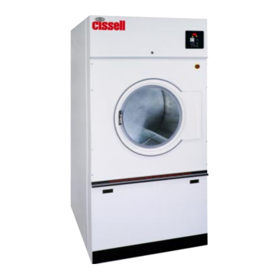
30 lb. SLIM HD LAUNDRY DRYER
Gas: Natural and LP
Steam
Electric
Technical specifications
Installation instructions
Operating instructions
Maintenance
Cissell Manufacturing Co.
HD30SL
831 S. First St. - P.O.Box 32270 - Louisville, Ky. - 40232-2270
Tel: (502) 587-1292 - Fax: (502) 585-2333
Sales Fax: (502) 585-3625 - Service/Parts Fax: (502) 681-1275
THIS MANUAL MUST BE GIVEN TO THE EQUIPMENT OWNER
MANHD30SL 7/02
Advertisement
Table of Contents

Subscribe to Our Youtube Channel
Related Manuals for Cissell MANHD30SL


Summary of Contents for Cissell MANHD30SL
- Page 1 Electric Technical specifications Installation instructions Operating instructions Maintenance Cissell Manufacturing Co. HD30SL 831 S. First St. - P.O.Box 32270 - Louisville, Ky. - 40232-2270 Tel: (502) 587-1292 - Fax: (502) 585-2333 Sales Fax: (502) 585-3625 - Service/Parts Fax: (502) 681-1275...
-
Page 2: Safety Instructions
IMPORTANT NOTICES—PLEASE READ For optimum efficiency and safety, we recommend that you read the manual before operating the equipment. Store this manual in a file or binder and keep for future reference. WARNING: Purchaser must post the following notice in a prominent location: WARNING: For your safety, the information in this manual must be followed to minimize the risk of fire or explosion or to prevent property damage, personal injury or death. - Page 3 ATTENTION: L’ACHETEUR DOIT PLACER L’AVERTISSEMENT SUIVANT DANS UN ENDROIT CLAIR ET VISIBLE: AVERTISSEMENT. Assurez-vous de bien suivre les instructions donnees dans cette notice pour reduire au minimum le risque d’incendie ou d’explosion ou pour eviter tuot dommage materiel, toute blessure ou la mort. __ Ne pas entreposer ni utiliser d’essence ni d’autres vapeurs ou liquides inflammables dans le voisinage de cet appareil ou de tout autre...
- Page 4 WARNING: To avoid fire hazard, do not dry articles containing foam rubber or similar texture materials. Do not put into this dryer flammable items such as baby bed mattresses, throw rugs,undergarments (brassieres, etc.) and other items which use rubber as padding or backing. Rubber easily oxidizes causing excessive heat and possible fire.
-
Page 5: Cissell Dryer Warranty
Cissell's factory, transportation prepaid, within the applicable warranty period and found by Cissell to have been defective, and in no event shall Cissell be liable for damages of any kind, whether for any injury to persons or property or for any special or consequential damages. -
Page 6: Table Of Contents
Contents Safety Instructions ................... 2-4 Cissell Dryer Warranty ................... Table of Contents ..................... Symbols ......................Unpacking / General Installation ..............8-9 Technical Data and Dimensions ..............10-11 Electric Connections ..................12 Gas Connections ....................13 Gas Piping Installation ................... 14-15 Gas service Installation Instructions ............. -
Page 7: Symbols
SYMBOLS The following symbols are used in this manual and/or on the machine. Symbol Description Symbol Rotation in two directions Rotation dans les deux sens NOTE! Drehbewigung in zwei Richtungen Movimiento rotativo en los Hot! Do Not Touch dos sentidos Heiß! Nicht Beruhren Direction of rotation Haute temperature! Ne pas... -
Page 8: Unpacking / General Installation
Unpacking/General Installation (All Dryers) Upon arrival of the equipment, any damage in shipment should be reported UNPACKING to the carrier immediately. Upon locating permanent location of a unit, care should be taken in movement and placement of equipment. See outline clearance diagrams for correct dimensions. Remove all packing material such as: tape, manuals, skid, etc. - Page 9 Unpacking/General Installation (All Dryers) The dryer is so designed that when an operator opens the dryer door, GENERAL the basket and exhaust fan stop. You can expect fast drying from the INFORMATION laundry dryer. Hot, dry air is properly and effectively moved through the basket and exhausted through a lint trap to the atmosphere.
-
Page 10: Technical Data And Dimensions
HD30SL Dryer Dimensions - Standard Gas, Steam and Electric Heated M e t r ic S p e c if i c a t io n s U . S . M e a s u r e M e a s u r e C a p a c it y 3 0 l b s . - Page 11 HD30SL Dryer Dimensions (Illustration) Page 11...
-
Page 12: Electric Connections
Electric connection Dryers must be electrically grounded by a separate #14 or larger green wire from the grounding terminal within the Service Connection Box, to a cold water pipe. In all cases, the grounding method must comply with local electrical code requirements; or in the absence of local codes, with the National Electrical Code, ANSI/NFPA 70 or the Canadian Electrical Code, CA C22.1. -
Page 13: Gas Connections
Gas connection The gas supply pipe should be connected to the union (I), which is on the right next to the wiring box on the back. It is very important to have the connections done by a qualified technician, in order to make sure that the installation is effected in accordance with the prevailing standards and instructions. -
Page 14: Gas Piping Installation
Gas Piping Installation 1. The installation must conform with local codes, or in the GAS PIPING absence of local codes with the National Fuel Gas Code as, INSTALLATION ANSI Z223.1 or the CAN/CGA-B149, Installation Codes. 2. Check identification nameplate for type of gas for dryer. 3. - Page 15 Gas Piping Installation (Illustrations) The dryer and it’s individual shutoff valve must be disconnected from the gas supply piping system during any pressure testing of that system at test pressures in excess of 1/2 psi (.04 bar). The dryer must be isolated from the gas supply piping system by closing it's individual manual shutoff valve during any pressure testing of the gas supply piping system at test pressures equal to or less than 1/2 psi (.04 bar).
-
Page 16: Gas Service Installation Instructions
Gas Service Installation Instructions The size of the gas service pipe is dependant upon many variables, GAS SERVICE such as tees, lengths, etc. Specific pipe size should be obtained from INSTALLATION the gas supplier. Refer to the “Gas Pipe Size” chart in this manual for INSTRUCTIONS general gas pipe size information. -
Page 17: Gas Pipe Size Chart
Gas Pipe Size Chart TOTAL BTU/HR GAS PIPE SIZE FOR 1000 BTU (250 KCAL) NATURAL GAS (for LP Gas correct AT 7” (17.5 MM) W.C. PRESSURE TOTAL total BTU/HR below by KCAL multiplying by .6) In figuring total length of pipe, make allowance for tees and elbows. HOUR (25 ft.) (50 ft.) -
Page 18: Steam Piping Installation Instructions
Steam Piping Installation Instructions STEAM PIPING 1. Set and anchor dryer in position. Machine should be level to INSTALLATION assure proper steam circulation. INSTRUCTIONS 2. To prevent condensate draining from headers to dryer, piping should have a minimum 12" above respective header. Do not make steam connection to header with a horizontal or downwardly facing tee or elbow. - Page 19 Steam Piping Installation (Illustration) Page 19...
-
Page 20: Dryer Installation With Multiple Exhaust
Dryer Installation With Multiple Exhaust For Exhaust Duct less than 14 feet (5 m) and 2 elbows equivalent and less than 0.3 inches (.8 mbar)static pressure. DRYER EXHAUSTS Area of section “A-A” must be equal to the sum of dryer exhaust pipes entering multiple exhaust pipe. - Page 21 Dryer Installation with Multiple Exhaust For Exhaust Duct more than 14 feet (5 m) and 2 elbows equivalent and more DRYER INSTALLATION than 0.3 inches (.8 mbar) static pressure. (See illustration on page 21.) WITH MULTIPLE EXHAUST 1. Make-up air from outside building may enter enclosure from top or side walls. (See Dryer Make-Up Air Chart on page 22) 2.
-
Page 22: Dryer Make-Up Air Requirements
Suggested Minimum Dryer Make-up Air Requirements Dryer Dryer Pocket Maximum Air Flow Duct Size For Required Make-up Model Capacity Rate per Pocket Service Connection Air Area per Pocket m3/h inch sq. inch cm2 C 30 ST 13.6 C 75 ST 1000 1700 1240... -
Page 23: Dryer Installation With Seperate Exhaust
Dryer Installation With Separate Exhaust (Preferred) For ductwork less than 14 feet (5 m) and 2 elbows equivalent and less than DRYER INSTALLATION 0.3 inches (.8 mbar) static pressure: WITH SEPARATE EXHAUST (PREFERRED) NEVER exhaust the dryer into a chimney. NEVER install wire mesh screen over the exhaust or make-up air area. -
Page 24: Exhaust And Venting
Exhaust and Venting Nothing is more important than air flow for the proper operation of a clothes dryer. DRYER AIR FLOW INSTALLATION A dryer is a pump which draws make-up air from the out-of-doors, through the heater, through the clothes and then forces the air through the exhaust duct back to the out-of-doors. -
Page 25: Rules For Safe Operation Of Dryer
Rules for Safe Operation of Dryer 1. Be sure your dryer is installed properly in accordance with the RULES FOR SAFE recommended instructions. OPERATION OF DRYER 2. CAUTION Be safe—shut main electrical power supply and gas supply off externally before attempting service. 3. -
Page 26: Direct-Spark Ignition Operation
Direct-Spark Ignition Operation NOTE: All dryers manufactured are equipped with the DSI (direct spark DIRECT SPARK ignition) modules. These are designed to increase dryer efficiency and to reduce IGNITION dryer operating costs. The main burner is directly ignited from a spark electrode. OPERATION A burning flame provides an electrical path for a small amount of sensing current to allow gas valve operation. -
Page 27: Direct-Spark Ignition Operation
DIRECT SPARK IGNITION OPERATION FLOW CHART The DSI module is powered by a 24 volts AC suppled by a step-down transformer in series with eight safety interlocks: A. Timer switching device (1) B. Main door and lint door switches (2) C. -
Page 28: General Maintenance
General Maintenance 1. Clean lint trap daily. Remove lint before or after each day of GENERAL MAINTENANCE operation. A clean lint trap will increase the efficiency of the dryer and the moisture-laden air will be exhausted outside more quickly. 2. Keep basket and sweep sheets clean. Clean as often as needed. -
Page 29: General Maintenance
General Maintenance 7. Periodically clean and examine exhaust system. GENERAL MAINTENANCE (continued) 8. Keep dryer area clean and free of gasoline, combustible materials and other flammable liquids or vapors. 9. Do not obstruct the flow of combustion (make-up) air and ventilating air. -
Page 30: Air Switch Adjustment
Air Switch Adjustment 1. Shut off current; disconnect leads and remove air switch. AIR SWITCH ADJUSTMENT 2. Lay air switch assembly on flat surface. Adjust air blade at “A” (figure 1) so that air blade lays flat and surface “B” is parallel to the flat surface. -
Page 31: Operating Instruction For Double Timer
OPERATING INSTRUCTION - DOUBLE TIMER OPERATING INSTRUCTIONS - DOUBLE TIMER MODELS 1. After loading the dryer with water washed clothes, close the loading door. 2. Turn the 60 minute drying (heat) timer to the desired time. 3. Turn the 15 minute cooling (air) to the desired time. 4. -
Page 32: Aligning Basket
INSTRUCTIONS FOR ALIGNING BASKET ON CISSELL DRYER Rear of Dryer Fig. 3 1. Loosen the 4 cast iron bearing bolts (1, 2, 3 & 4) on rear of dryer, and 2 adjusting bolts #5, on gear reducer housing. (Fig. 3). -
Page 33: Front View
FRONT VIEW Ref. Part No. Description TU15131 CSA-01435-0 Coin chute w/a EA-11621-0 Microswitch lint door SC404 Pop rivet TU10290 Lint trap w/a TU10362 Lint Screen TU5225 Lint screen frame TU15030WH Jacket (white) TU3211 Leveling bolt 430146179 Gasket, 5 feet TU7733 Screw self drilling 8-18 X 1/2"... -
Page 34: Control Door Assembly
ACCESS DOOR ASSEMBLY Ref. Part No. Description CSA-01415* - Access Door Complete CA-00855-0 Trim - Control door LA-00121-0 Lock - Control door LA-11941-0 Cam lock-Control door SB-00951-0 Screw -Phillips #8 X 7/16 flat hd. TU14957 Logo CSA-01416* Panel - Welded asm. TU15446 Support arm. -
Page 35: Door Assembly
DOOR ASSEMBLY Ref. Part No. Description TU15110 Complete door assy (Indicate color) CA-13218 Catch pin TU15536 Magnet - read switch MD-00360-0 Gasket - door rim gasket SB-00852-0 Washer 1/4" external starluck SB-00921-0 Screw 1/4"-20 round head TU15073 Door hinge spacer TU15076 Door rim w/a TU15107... -
Page 36: Front Panel Assembly - Opl
FRONT PANEL ASSEMBLY - OPL Ref. Part No. Description TU14545WHT - Front panel assembly complete (E-stop button) TU15725WHT - Front panel assembly complete (with out E-stop button) ESA-00862-0 Reed switch SB-00975-0 #6-32 Screw TU14435 Emergency stop TU14543WHT Front panel W/A - OPL TU2876 Door catch TU3213... -
Page 37: Front Panel Assembly - Coin
FRONT PANEL ASSEMBLY - COIN Ref. Part No. Description CSA-01413WH - Front panel assembly complete CA-00699-0 Bezel - Coin box ESA-00862-0 Reed switch SB-00975-0 #6-32 Screw SB-00924-0 4-40 x 3/8 Screw SB-00938-0 #4 Ext. tooth lockwasher CSA-01414WH Front panel W/A - Coin TU2876 Door catch TU3213... -
Page 38: Thermostat Assembly
THERMOSTAT ASSEMBLY FOR DOUBLE TIMER Ref. Part No. Description CA-13214-0 Plate EA-00411-0 Thermostat - 220 Degree EA-00606-0 Thermostat EA-00607-0 Thermostat knob EA-00608 - 0 Grommet / rubber SB-00828-0 Screw 8-32 X 1/2” TU15010 Thermostat bracket TU3266 Nut-brass 8-32 TU3624 Screw 6 - 32 X 1/4” TU7733 Screw - self drilling 8 - 18 X 1/2”... - Page 39 THERMOSTAT ASSEMBLY FOR DMP COIN & OPL Ref. Part No. Description ESA-00961-0 - Complete Assmebly CA-13172 Mtg. bracket EA-00411 Switch - 220 Degree SB-00828 #8-32x1/2 Screw SB-00952 #6-32x3/8 Screw TU11991 Thermistor TU3266 #8-32 Hex nut TU3400 #6-32 Hex nut Page 39...
- Page 40 PROHC SENSOR ASSEMBLY - UPPER and LOWER Ref. Part No. Description TU14724 PROHC Sensor assembly (upper) SB-00952-0 Screw, #6-32x 3/8” long TU14693 Mounting plate upper probe TU14694 Cover plate, probe TU3400 Nut, #6-32 TU7733 Screw, self drill #8-18x 1/2” long 254/00060/10 Humidity sensor UPPER ASSEMBLY...
-
Page 41: Mech. Coin Control Asm
#10-16 Screw TUD0355 Overlay TU12253 #6-32 Stud TUT316 LED light 24V W 1/4 Q.C. TU15250 Control panel SEE BELOW TIMER MOTORS CISSELL PART N0. VENDOR PART NO. NO. OF PINS 30 MIN 60 MIN TU3009 59-439-2 TU3010 59-439-3 TU3011 59-439-4... -
Page 42: Dmp Coin Control Assembly
DMP COIN CONTROL ASSEMBLY TU15256 - Complete Assembly TU15255 Control panel w/a M262 Screw, mach truss HD #8-32X3/8" TU14404 Controller OPL/COIN board new TU14406 Overlay TU3266 Nut, hex-brass #8-32 TU3400 Nut, hex #6-32 TUD0336 Coin drop-hanke, 25 C. TUD0367 Nut, hex - #5-40 machine TU12253 Stud, self clinch TU1771... -
Page 43: Timer Control Assembly
CONTROL PANEL ASSEMBLY (DUAL TIMER) REVERSING and NON-REVERSING TU15248 Control panel assembly (Non-Reversing) TU15249 Control panel assembly (Reversing) * - Parts used on TU15249 only Ref. Ref. Part No. Description Part No. Description EA-00619-0 Switch - start TU14931* Bracket, mounting rev. board FG147* Toggle switch spst 2 position TU14936... -
Page 44: Dmp Opl Control Assembly
DMP OPL CONTROL ASSEMBLY Ref. Part No. Description TU15254 - Reversing Control Panel Complete TU15252 Control panel M262 #8-32 Screw TU14137 Buzzer 24V (Optional) TU14404 DMP Control TU15184 Overlay TU3400 #6-32 Nut TU12253 #6-32 Stud M270 #6 Lockwasher TU1771 Speed nut twin type Page 44... -
Page 45: Pro/Hc Control Assembly
PROHC CONTROL PANEL ASSEMBLY Ref. Part No. Description TU15298 Reversing/Non Reversing Complete Assembly 254/00070/00 PCboard, professional 254/00018/00 Lable, PRO moisture controller M262 Screw, machine truss #8-32x 3/8” long TU3266 Nut, hex brass #8-32 TU3400 Nut, hex #6-32 TU14701 Spacer nylon 1/4” O.D. x 5/16” long TU14452 Chip, EPROM, PROHC TU15257... -
Page 46: Lint Door Assembly
LINT DOOR ASSEMBLY Ref. Part No. Description TU15664* Lint door complete Assembly - OPL TU15660* Lint door complete Assembly - Coin TU15656* Lint door W/a (OPL & Coin) SB-00949-0 Fastener plastic kickplate CA-00645-0 Lint door handle CA-00828-0 Kickplate SB-00836-0 Screw, Pancake #10 CA-00655-0 Trim, Rubrail - specify 33”... -
Page 47: Basket & Spider Assembly
BASKET & SPIDER ASSEMBLY Ref. Part No. Description TUS15105 Basket & Spyder Asm. - S.S. TU15105 Basket & Spyder Asm. - Galv. TUS15068 Stainless steel basket assy. TU15068 Galvanized basket assy. TU15087 Spider assy. SB-00965-0 Screw-button cap 5/16 - 18 TU7006 Shim VSB130... -
Page 48: Rear View
REAR VIEW Ref. Part No. Description TU14725 Cover plate TU15030WH Jacket (white) TU15150 Upper rear cover TU15151 Lower rear cover TU7733 Screw self drilling 8-18 x 1/2" TU15671 Air switch cover Page 48... -
Page 49: Air Switch Assembly
AIR SWITCH ASSEMBLY - TU8206 Part No. Description F888 E-RING TU1770 INSULATOR TU1771 #6 TINNERMAN NUT TU2463 ACTUATOR ARM TU3219 #6 x 1 S.M.S. TU3476 DECAL TU7733 #8 x 1/2 S.M.S. TU8155 MICRO SWITCH TU8171 BRACKET ASM. Page 49... -
Page 50: Basket Bearing/Sheave Assy
BASKET BEARING AND SHEAVES Part No. Description Part No. Description TU15173 18” Dia. Sheave (Non-reversing) TU1851 1/2 Flat washer TU15157 18” Dia. Sheave (Reversing) RC347 1/2-13 x 1 1/4” H.H. Screw TU15153 1 1/4” Tappered Bushing TU2831 1/2 Lock washer TU15304 1/4”... -
Page 51: Motor & Fan Assembly
MOTOR & FAN ASSEMBLY- NON-REVERSING **** Motor Ref. Voltage Part No. Description Part No. Description 110-120/60/1 DA-00428-0 SINGLE MOTOR MTR314 FAN-DOUBLE MOTOR C249 Nut, 5/16-18 (4 each) MTR315 BASKET-DOUBLE MOTOR 200-240/60/1 DA-00428-0 SINGLE MOTOR DA-00460-0 Seal MTR314 FAN-DOUBLE MOTOR **** Motor, see chart on page MTR315 BASKET-DOUBLE MOTOR... - Page 52 MOTOR ASSEMBLY- REVERSING Ref. Part No. Description **** Motor, see chart on page 50 TU6559 Sheave, 2” dia. (60 Hz) TU10998 Sheave (50 Hz) VSB130 Washer, cut 5/16” TU2814 Washer, lock 5/16” TU5439 Screw, cap HH 5/16-18 Page 52...
-
Page 53: Idler Assembly
IDLER ASSEMBLY Ref. Ref. Part No. Description Part No. Description SB-00935-0 Screw 5/16-18x 3” Reversing TU15205 Belt, upper (Basket) TU2814 Lock Washer 5/16" TU5439 Screw 5/16-18x 1" DA-00522-0 Belt, lower (Motor) Non-reversing TUD0187 Key 3/16” square 2 1/2” VSB130 Washer 5/16" TU15205 Belt, upper (Basket) TU15206... -
Page 54: Rear Control Box Assembly
REAR CONTROL PANEL ASSEMBLY - GAS Ref. Ref. Part No. Description Part No. Description TU14958 T-Block CA-11935-0 Rear wiring box TU14959 T-Block end EA-00680-0 Plug knock out TU14985 Din rail EA-00685-0 Reverse control, 24V coil TU15007 T-Block ground end SB-00865-0 Screw, phillips head TU15265 Terminal Board... -
Page 55: Nat. Gas Heating Unit Asm
NATURAL GAS HEATING UNIT Ref. Ref. Part No. Description Part No. Description TU15129 - Complete assembly TU7733 #8-12 Screw, self drilling TU15693 Ignitor mtg. bracket FG274 1/2” x 30# lg. Nipple CA-11028-0 Bracket, HI limit TU15106 Burner cover plate GA-11006-0 Manifold OP290 1/2”... -
Page 56: Gas Heating Unit Asm
L.P. GAS HEATING UNIT Ref. Ref. Part No. Description Part No. Description TU15222 - Complete assembly TU7733 #8-12 Screw, self drilling TUD0242 Ignitor mtg. bracket FG274 1/2” x 30# lg. Nipple CA-11028-0 Bracket, HI limit TU15106 Burner cover plate GA-11006-0 Manifold OP290 1/2”... -
Page 57: Steam Heating Unit Asm
STEAM HEATING UNIT Ref. Part No. Description CSA-01675-0 Complete assembly CA-13220-0 Steam coil CFB0900 Cable, GREENFIELD 1/2" X 9" TU15246 Adaptor, w/a TU13517 Valve, steam solenoid 3/4” 24V TU14591 Bushing 1” to 3/4” TU4608 Nipple, 3/4” x 2” black TU4790 Connector TU7733 Screw, self dr. -
Page 58: Electric Heating Unit Asm
ELECTRIC BONNET ASSEMBLY Ref. Part No. Description ESA-00254-0 - Complete Assembly CA-11984-0 Rear heater box cover EA-00243-0 Bonnet high limt switch EA-00472-0 Heater element (240V) EA-00473-0 Heater element (208 V) EA-10232-0 Switch cover EA-10417-0 Jumper bars EA-11373-0 Heater box back ESA-00610-0 Heater box housing ESA-00948-0... -
Page 59: Recommended Spare Parts List
RECOMMENDED SPARE PARTS LIST BELTS EA-11621-0 LINT DOOR SWITCH CA-13033-0 20-30# LINT SCREEN DA-00533-0 NON-REV UPPER BELT 20/30SL TU5261 30SL, 50,75# LINT SCREEN TU15206 NON-REV LOWER BELT 20/30SL MD-00337-0 MAGNET –READ SWITCH DA-00533-0 REV UPPER BELT 20/30SL MD-00360-0 GASKET DOOR RIM DA-00522-0 REV LOWER BELT 20/30SL... - Page 60 Page 60...
Need help?
Do you have a question about the MANHD30SL and is the answer not in the manual?
Questions and answers