Lenovo ThinkPad T420 User Manual
Thinkpad t420; thinkpad t420i
Hide thumbs
Also See for ThinkPad T420:
- (295 pages) ,
- Podręcznik użytkownika (294 pages) ,
- Käyttöopas (286 pages)
Table of Contents
Advertisement
Advertisement
Table of Contents

Related Manuals for Lenovo ThinkPad T420


Summary of Contents for Lenovo ThinkPad T420
-
Page 1: User Guide
User Guide ThinkPad T420 and T420i... - Page 2 First Edition (February 2011) © Copyright Lenovo 2011. LENOVO products, data, computer software, and services have been developed exclusively at private expense and are sold to governmental entities as commercial items as defined by 48 C.F.R. 2.101 with limited and restricted rights to use, reproduction and disclosure.
-
Page 3: Table Of Contents
Fingerprint Software... Using the ThinkLight feature ..Lenovo ThinkVantage Tools ..Using the optical drive . - Page 4 Passwords and sleep (standby) mode ..Inserting the hard disk drive adapter into the bay ....Typing passwords ... ThinkPad Port Replicator Series 3, ThinkPad Mini Power-on password .
- Page 5 Lenovo Support Web site..Calling Lenovo ... . . Trademarks ....
- Page 6 User Guide...
-
Page 7: Read This First
© Copyright Lenovo 2011... -
Page 8: Important Safety Information
This information can help you safely use your notebook personal computer. Follow and retain all information included with your computer. The information in this document does not alter the terms of your purchase agreement or the Lenovo Limited Warranty. For more information, see the Safety and Warranty Guide came with your computer. -
Page 9: Conditions That Require Immediate Action
Note: If you notice these conditions with a product (such as an extension cord) that is not manufactured for or by Lenovo, stop using that product until you can contact the product manufacturer for further instructions, or until you get a suitable replacement. - Page 10 product are zero. Before you remove the covers from a product equipped with a power cord, always make sure that the power is turned off and that the product is unplugged from any power source. If you have any questions or concerns, contact the Customer Support Center. Although there are no moving parts in your computer after the power cord has been disconnected, the following warnings are required for your safety.
-
Page 11: Power Cords And Power Adapters
Never overload these devices. If power strips are used, the load should not exceed the power strip input rating. Consult an electrician for more information if you have questions about power loads, power requirements, and input ratings. © Copyright Lenovo 2011... -
Page 12: Plugs And Outlets
Plugs and outlets DANGER If a receptacle (power outlet) that you intend to use with your computer equipment appears to be damaged or corroded, do not use the outlet until it is replaced by a qualified electrician. Do not bend or modify the plug. If the plug is damaged, contact the manufacturer to obtain a replacement. -
Page 13: Rechargeable Battery Notice
In addition, many mobile products, such as notebook computers, utilize a rechargeable battery pack to provide system power when in portable mode. Batteries supplied by Lenovo for use with your product have been tested for compatibility and should only be replaced with approved parts. -
Page 14: Lithium Coin Cell Battery Notice
Lithium coin cell battery notice DANGER Danger of explosion if battery is incorrectly replaced. When replacing the lithium coin cell battery, use only the same or an equivalent type that is recommended by the manufacturer. The battery contains lithium and can explode if not properly used, handled, or disposed of. -
Page 15: Heat And Product Ventilation
• Do not restrict or block any ventilation openings. • Do not operate your computer inside furniture, as this might increase the risk of overheating. • Airflow temperatures into the computer should not exceed 35° C (95° F). © Copyright Lenovo 2011 xiii... -
Page 16: Electrical Current Safety Information
Electrical current safety information DANGER Electric current from power, telephone, and communication cables is hazardous. To avoid a shock hazard: • Do not use your computer during a lightning storm. • Do not connect or disconnect any cables or perform installation, maintenance, or reconfiguration of this product during an electrical storm. -
Page 17: Modem Safety Information
• The LCD is made of glass, and rough handling or dropping the computer can cause the LCD to break. If the LCD breaks and the internal fluid gets into your eyes or on your hands, immediately © Copyright Lenovo 2011... -
Page 18: Using Headphones Or Earphones
50332-2 can be dangerous due to excessive sound pressure levels. If your Lenovo computer came with headphones or earphones in the package, as a set, the combination of the headphones or earphones and the computer already complies with the specifications of EN 50332-1. -
Page 19: Chapter 1. Product Overview
• “Front view” on page 2 • “Right-side view” on page 5 • “Left-side view” on page 7 • “Rear view” on page 10 • “Bottom view” on page 8 • “Status indicators” on page 11 © Copyright Lenovo 2011... -
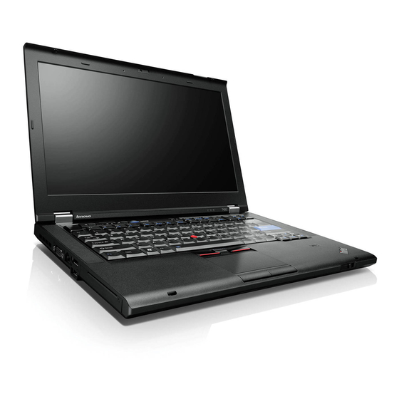
Page 20: Front View
Front view Figure 1. ThinkPad T420/T420i front view Power switch Computer display Fingerprint reader TrackPoint buttons TrackPoint pointing stick ThinkVantage button System and power-status indicators UltraConnect wireless antennas (left) Built-in microphone (left) Integrated camera ThinkLight Built-in microphone (right) UltraConnect wireless antennas (right) - Page 21 If your computer stops responding, and you cannot turn it off, press and hold the power switch for 4 seconds or more. If the system is still not reset, remove the ac power adapter and the battery. Fingerprint reader Some models have a fingerprint reader. The fingerprint authentication technology enables you to use your fingerprint to start the computer and enter the ThinkPad Setup.
- Page 22 ThinkLight You can use your computer under less than perfect lighting conditions. ® To illuminate the keyboard, turn on the ThinkLight by pressing Fn+PgUp. To turn it off, press Fn+ PgUp again. Built-in stereo speaker (right) Built-in stereo speaker (left) The stereo speakers are built into your computer.
-
Page 23: Right-Side View
Right-side view Figure 2. ThinkPad T420/T420i right-side view Security keyhole USB connector eSATA/USB combo connector ExpressCard slot Media card reader slot Wireless radio switch Serial Ultrabay enhanced Combo audio jack Security keyhole Your computer comes with a security keyhole. You can purchase a security cable and lock to fit this keyhole. - Page 24 For details, refer to the instructions in “Using the media card reader” on page 79. Media card reader slot Depending on the model, your computer may have a media card reader slot. The media card reader supports the following cards: •...
-
Page 25: Left-Side View
Left-side view Figure 3. ThinkPad T420/T420i left-side view Fan louvers (left) Monitor connector Ethernet connector DisplayPort connector USB connector (left) Smart card slot Fan louvers (left) The internal fan and louvers enable air to circulate in the computer and cool the central processor. -
Page 26: Bottom View
Note: Your computer is compatible with USB 1.1 and 2.0. Smart card slot Your computer has the Smart card slot. For details, refer to the instructions in “Using the media card reader” on page 79. Bottom view Figure 4. ThinkPad T420/T420i bottom view User Guide... - Page 27 Your computer might include a PCI Express Mini Card in the PCI Express Mini Card slot which enables wireless WAN communications. With Lenovo technologies advancing to provide you with the best engineered systems, some models are equipped with a mSATA solid state drive for data storage.
-
Page 28: Rear View
Rear view Figure 5. ThinkPad T420/T420i rear view. Modem connector or IEEE 1394 Always On USB connector (rear) Power jack Fan louvers (rear) Modem connector or IEEE 1394 • If your computer has a modem connector, connect your computer to a telephone line with the modem connector. -
Page 29: Status Indicators
Fan louvers (rear) The internal fan and louvers enable air to circulate in the computer and cool the central processor. Note: To avoid impeding airflow, do not place any obstacle in front of the fan. Status indicators The status indicators show the current status of your computer. System-status indicators Device Access A hard disk drive or an optional drive, such as a drive in the Ultrabay, is being used to read or write data. - Page 30 moving the cursor. To enable or disable this mode, press ScrLk. Not all application programs support this function. Power-status indicators The computer has status indicators that show the mode (sleep/standby, hibernation, or normal), ac power status, the status of the battery. The following shows the location and the meaning of the indicators: Sleep (standby in Windows XP) status •...
-
Page 31: Locating Important Product Information
Certificate of Authenticity (COA) label. Machine type and model label The machine type and model label identifies your computer. If you contact Lenovo for help, the machine type and model number will enable support technicians to identify your computer and provide the highest level of service. -
Page 32: Fcc Id And Ic Certification Number Label
You can find the machine type and model of your computer in the label as shown below: FCC ID and IC Certification number label There is no FCC ID or IC Certification number for the PCI Express Mini Card shown on the enclosure of your computer. -
Page 33: Certificate Of Authenticity Label
If no integrated wireless PCI Express Mini Card has been preinstalled in your computer, you can install one. To do this, follow the procedure in “Installing and replacing a PCI Express Mini Card for wireless LAN/WiMAX connection” on page 130 or “Installing and replacing the PCI Express Mini Card for wireless WAN”... -
Page 34: Features
The Certificate of Authenticity of your computer is shown as below: Features Processor • To see the system properties of your computer, click Start, right-click Computer (in Windows XP, My Computer); then from the pull down menu select Properties. Memory •... -
Page 35: Specifications
• Speaker mute button • Microphone mute button Interface • External monitor connectors (VGA and DisplayPort) • Combo audio jack (stereo headphone or headset) • 2 Universal Serial Bus (USB) connectors • 1 Always On USB connector • 1 eSATA/Universal Serial Bus (USB) connector (on some models) •... -
Page 36: Operating Environment
Do not eat or smoke over your keyboard. Particles that fall into your keyboard can cause damage. ThinkVantage Technologies and software Lenovo preinstalls on your PC useful and helpful software applications to help you get started, to stay productive while on the move and to keep you and your computer working. Lenovo offers enhanced security, wireless computing, data-migration and other solutions for your computer. -
Page 37: Accessing Applications In Windows 7
Click Start ➙ All Programs ➙ Lenovo ThinkVantage Tools. Then depending on the application you want to access, double-click the corresponding icon. Note: If an application icon in the Lenovo ThinkVantage Tools application navigation window is dimmed, it indicates that you need to install the application manually. To install the application manually, double-click the application icon. -
Page 38: Access Connections
Note: If you do not find the application you need in Control Panel, open the Lenovo ThinkVantage Tools application navigation window and double-click the dimmed icon to install the application you need. Then, follow the instructions on the screen. When the installation process completes, the application icon will be activated, and you can find the application in Control Panel. -
Page 39: Active Protection System
• For Windows Vista and Windows XP: Click Start ➙ All Programs ➙ ThinkVantage ➙ ThinkVantage Fingerprint Software. Lenovo ThinkVantage Tools The Lenovo ThinkVantage Tools program helps you work more easily and securely by providing easy access to various technologies, such as: • Lenovo ThinkVantage Toolbox •... -
Page 40: Lenovo Thinkvantage Toolbox
To open Lenovo ThinkVantage Toolbox, do the following: • For Windows 7: See “Accessing applications in Windows 7” on page 19. • For Windows Vista and Windows XP: Click Start ➙ All Programs ➙ ThinkVantage ➙ Lenovo ThinkVantage Toolbox. For additional information about running the Lenovo ThinkVantage Toolbox program, refer to the Lenovo ThinkVantage Toolbox help system. -
Page 41: Presentation Director
(ThinkVantage applications, device drivers, UEFI BIOS updates, and other third party applications). Some examples of software that you should keep updated are programs provided by Lenovo, such as the Rescue and Recovery program. To open the System Update, do the following: •... - Page 42 User Guide...
-
Page 43: Chapter 2. Using Your Computer
“Using the media card reader” on page 79 Register your computer When you register your computer, information is entered into a database, which enables Lenovo to contact you in case of a recall or other severe problem. In addition, some locations offer extended privileges and services to registered users. - Page 44 100. Getting connected in different locations is a challenge? • To troubleshoot a wireless networking issue, see http://www.lenovo.com/support/faq. • Take advantage of the networking features by use of “Access Connections” on page 20.
-
Page 45: Special Keys And Buttons
• Also “Recovery tool” on page 105 is provided on your computer hard disk or solid state drive. For more information, see Chapter 5 “Recovery overview” on page 103. Print the following sections and keep them with your computer in case you are unable to access this online help when necessary. -
Page 46: Function Key Combinations
If the numeric keypad is enabled, press and hold Shift to use the cursor- and screen-control keys temporarily. Note: The functions of the cursor- and screen-control keys are not printed on the keys. Function key combinations By setting the function keys, you can change operational features instantly. To use this function, press and hold the Fn key (1);... - Page 47 Note: If you have logged on with an administrator user ID in Windows XP, and you press Fn+F3, the panel for selecting a power scheme appears. If you have logged on with another user ID in Windows XP, and you press Fn+F3, the panel does not appear. •...
- Page 48 – External monitor – Computer display and external monitor – Computer display Notes: – This function is not supported if different desktop images are displayed on the computer display and the external monitor (the Extend desktop function). – This function does not work while a DVD movie or a video clip is playing. To enable this function, start Presentation Director, and change the settings.Click Start ➙...
-
Page 49: Volume And Mute Buttons
• Fn+Spacebar: Enable the FullScreen Magnifier function. • Fn+F2: Lock your computer. • Fn+F8: Change the settings of the UltraNav pointing device. • Fn+PrtSc: Have the same function as the SysRq key. • Fn+ScrLk: Enable or disable the numeric keypad. The indicator of numeric lock is displayed on the screen. - Page 50 For Windows 7 and Windows Vista: 1. Click Start ➙ Control Panel ➙ Hardware and Sound ➙ Sound. The Sound window appears. 2. Click the Playback tab or Recording tab, and then click a device, which you want to customize. 3.
-
Page 51: Windows Key And Application Key
Windows key and Application key The following two keys are on your computer keyboard: Windows key If you press this key, the Start menu of Windows is displayed or hidden. If you press this key and another key at the same time, the System Properties window or the Computer (in Windows XP, My Computer) window is displayed. -
Page 52: Using The Trackpoint Pointing Device
Changing the UltraNav settings You can change your settings of UltraNav in the UltraNav tab of the Mouse Properties window. To open it, use one of the following methods: • Press Fn+F8, and the UltraNav Device Settings window is displayed. In this window, click Manage Settings. -
Page 53: Using The Touch Pad
Customizing the TrackPoint You can customize the TrackPoint pointing device and its buttons as follows: • Switch the functions of the left and right buttons. • Change the sensitivity of the TrackPoint. • Enable the Press-to-Select function. • Enable the Magnifying Glass. •... -
Page 54: Behavior Of The Ultranav And An External Mouse
Using the multi-touch touch pad The touch pad of your computer supports multi-touch with which you can zoom in, zoom out, scroll or rotate on the screen while browsing the Internet or reading or editing a document. For details, refer to the Help in the UltraNav. Customizing the touch pad To customize the touch pad, do as follows: 1. -
Page 55: Adding The Ultranav Icon To The System Tray
2. Click UltraNav tab. 3. To disable the TrackPoint, clear the check box for Enable TrackPoint. To disable the touch pad, clear the check box for Enable touch pad. 4. Click OK. For Windows XP 1. Click Start ➙ Control Panel ➙ Printers and Other Hardware ➙ Mouse. 2. -
Page 56: Using The Ac Power Adapter
• The way you use your computer: how often you access the hard disk drive or the solid state drive, how bright you make the computer display. Using the ac power adapter The power to run your computer can come either from the lithium-ion (Li-ion) battery pack provided with it, or from ac power through the ac power adapter. -
Page 57: Managing Your Battery Power
• Use the battery until the charge is completely depleted-until the battery status indicator starts blinking orange. • Recharge the battery completely before using it. The battery is fully charged if the battery indicator shows green when the ac power adapter is plugged in. •... -
Page 58: Handling The Battery
Do not attempt to disassemble or modify the battery pack. Attempting to do so can cause an explosion, or liquid leakage from the battery pack. A battery pack other than the one specified by Lenovo, or a disassembled or modified battery pack is not covered by the warranty. - Page 59 The battery pack is a consumable supply. If your battery begins to discharge too quickly, replace the battery pack with a new one of the type recommended by Lenovo. For more information on replacing the battery pack, contact your Customer Support Center.
-
Page 60: Connecting To The Network
Connecting to the network Your computer has one or more network adapters for connecting to the Internet and to your company's wired LAN or wireless LAN network. Your modem enables you to connect to your network or the Internet from almost anywhere. If your network has a phone line or lines dedicated to dial-up clients, you can use a modem to establish a connection to the LAN. - Page 61 Your computer can be wireless upgradeable. This means that your computer has an antenna that can support wireless LAN access when wireless LAN access points are available. Wireless devices are available from Lenovo. For more information, refer to “Finding ThinkPad options” on page 149. Using wireless WAN connections Wireless Wide Area Network (wireless WAN) enables you to establish wireless connections over remote public or private networks.
-
Page 62: Using Bluetooth
To find the location of the wireless WAN antenna on your computer, refer to “Location of the UltraConnect wireless antennas” on page 244. To use the wireless WAN feature, start Access Connections. Using Bluetooth For Windows 7 and Windows Vista If your computer is equipped with the Integrated Bluetooth features, you can enable or disable the features by pressing Fn+F5. - Page 63 Some other virtual device drivers will be installed on demand when you use certain Bluetooth profiles for the first time. Using the Microsoft Bluetooth software If you are using Windows XP and want to use the Microsoft standard Bluetooth features, install the software by following the instructions in “Installing the Microsoft Bluetooth software in Windows XP”...
- Page 64 For more information, press the F1 key to open the online help for Bluetooth. Bluetooth Configuration To use the configuration features of Bluetooth, right-click the icon. A pop-up menu appears. Select Bluetooth Setup Wizard or Advanced Configuration. The Bluetooth Setup Wizard has the following capabilities: •...
- Page 65 2. Click Start ➙ Run. 3. Type C:\SWTOOLS\Drivers\TPBTooth\Setup.exe (or specify the full path to the setup.exe file you have downloaded from http://www.lenovo.com/support); then click OK. 4. Click Next. 5. Select I accept the terms in the license agreement; then click Next.
- Page 66 For Windows 7: To start the Access Connections wizard, see “Accessing applications in Windows 7” on page 19, and follow the instructions on the screen. For Windows Vista and Windows XP: To start the Access Connections wizard, click Start ➙ All Programs ➙ ThinkVantage ➙...
-
Page 67: Using The Built-In Modem
– Current location profile is disconnected. – Current location profile is connected. • Wireless status icon states: wireless LAN – Power to the wireless radio is off. – Power to the wireless radio is on. No association. – Power to the wireless radio is on. No signal. –... - Page 68 You can use the modem only on a public-switched telephone network (PSTN). You cannot use a private branch exchange (PBX) or some other type of digital telephone extension line. If you connect the modem to a line other than PSTN, an error message appears, preventing you from using the line. If you are not sure which kind of phone line you are using, contact your telephone company.
-
Page 69: Modem Commands
Industry standard fax support up to 14.4 Kbps: Fax protocols • V.21 Ch 2 (300-bps fax) • V.17 (up to 14.4-Kbps fax) • V.29 (9600-bps fax) • V.27ter (4800-bps fax) Computer telephony function support: • DTMF and pulse dialing • Detecting DTMF digits received from the phone line •... - Page 70 Table 3. Modem command list (continued) +F +F +FCL CL CLAS AS ASS S S =<Mode> +FCLASS <Mode> +FCLASS +FCLASS Select Active Service Class 0: Select Data Mode 1: Select Facsimile Class 1 Mode 1.0: Select Facsimile Class 1.0 Mode 8: Select Voice Mode +VCID ID ID=<pmode>...
- Page 71 Table 3. Modem command list (continued) \N<mode> \N \N <mode> \N \N Operating Mode 0: Selects normal speed buffered mode (disables error-correction mode) and forces &Q6 (selects asynchronous operation in normal mode.) 1: Same as 0. 2: Selects reliable (error correction) mode and forces &Q5 (the modem will try to negotiate an error corrected...
- Page 72 Table 3. Modem command list (continued) I I I [<value>] I I I <value> Request Identification Information 0: Reports product code. 1: Reports the latest significant byte of the stored checksum in decimal. 2: Reports OK. 3: Reports identification codes. 4: Reports product description from the .INF file.
- Page 73 Table 3. Modem command list (continued) W W W [<value>] W W W <value> Connect Message Control 0: Upon connection, the modem reports only the DTE speed. Subsequent responses are disabled. 1: Upon connection, the modem reports the line speed, the error correction protocol, and the DTE speed, respectively.
- Page 74 Table 3. Modem command list (continued) &D &D &D[<value>] &D &D &D DTR Behavior <value> 0: Modem ignores DTR. 1: Upon an on-to-off transition of DTR, the modem enters online command state and issues an OK result code; the call remains connected.
- Page 75 Table 3. Modem command list (continued) +IFC C C =[<modem_by_DTE> +IFC DTE-Modem Local Flow <modem_by_DTE> +IFC +IFC [,<DTE_by_modem>]] Control 0: None. 1: XON or XOFF on transmitted data; do not pass XON or XOFF characters to the remote modem. 2: Circuit 133. <...
- Page 76 Table 3. Modem command list (continued) H H H [<value>] H H H <value> Disconnect (Hang-Up) 0: The modem will release the line if the modem is currently on-line. 1: If on-hook, the modem will go off-hook and remain in command mode.
- Page 77 Table 3. Modem command list (continued) *B *B *B *B Display Blacklisted Numbers *D *D *D *D Display Delayed Numbers Last Call Status Report +P +P +PCW CW CW=<value> +PCW +PCW +PCW Call Waiting Enable <value> 0: Request modem-on hold if enabled by +PMH and collect caller ID information if enabled by +VRID.
-
Page 78: Modem Result Codes
Table 3. Modem command list (continued) +PQC QC QC=<value> +P +P +PQC <value> +PQC +PQC Shortened Phase 1/2 control 0: Enable Short Phase 1 and Short Phase 2. 1: Enable Short Phase 1 only. 2: Not supported. 3: Disable Short Phase 1 and Short Phase 2. - Page 79 Table 4. Modem result codes (continued) NO CARRIER Sent when attempting to establish a call if: Ringback is detected and later ceases but no carrier is detected within the period of time determined by register S7, or 1. No ringback is detected within the period of time determined by register S7.
- Page 80 Table 4. Modem result codes (continued) CONNECT 14400 The modem has connected to the line at 14400 bps and DCE speed reporting is enabled. CONNECT 19200 The modem has connected to the line and either the line speed is 19200 bps and DCE speed reporting is enabled, or the DTE speed is 19200 bps and DTE speed reporting is enabled.
- Page 81 Table 4. Modem result codes (continued) +MRR: 24000 The modem has connected to the line at 24000 bps and carrier reporting is enabled. (See S95 and Xn.) +MRR: 26400 The modem has connected to the line at 26400 bps and carrier reporting is enabled.
- Page 82 Table 4. Modem result codes (continued) +MCR: V22 The modem has connected to the line with ITU-T V.22 modulation and modulation reporting is enabled. (See +MR, S95 and Xn.) +MCR: V22B The modem has connected to the line with ITU-T V.22 bis modulation and modulation reporting is enabled.
- Page 83 Table 4. Modem result codes (continued) CONNECT 38000 The modem has connected to the line at 38000 bps and DCE speed reporting is enabled. CONNECT 40000 The modem has connected to the line at 40000 bps and DCE speed reporting is enabled. CONNECT 42000 The modem has connected to the line at 42000 bps and DCE speed reporting is enabled.
- Page 84 Table 4. Modem result codes (continued) CONNECT 50667 The modem has connected to the line at 50667 bps and DCE speed reporting is enabled. CONNECT 53333 The modem has connected to the line at 53333 bps and DCE speed reporting is enabled. CONNECT 54667 The modem has connected to the line at 54667 bps and DCE speed reporting is enabled.
- Page 85 S registers S registers are information storage areas inside the modem. The AT command set uses the S registers to configure modem options. Some S registers have default settings. These are usually adequate for normal modem operations. In special circumstances, however, you may need to change some defaults. To read or change the value of an S register, begin the command with the letters AT.
- Page 86 Table 5. S registers (continued) Register Description Range Units Data Compression Control 136 (no compression) or 138 (compression) Result Code Messages Control: Bit 0 CONNECT result code indicates DCE speed instead of DTE speed. Bit 1 Reserved. Bit 2 Enable +MCR:XXXX result code (XXXX=modulation) and +MRR:XXXX result code...
-
Page 87: Using A Projector Or External Display
Some countries support pulse dialing rather than tone dialing. To change dialing methods, refer to your Windows online help. Note: In many regions, you cannot use the built-in modem function until Lenovo has received approval from the proper authorities. Your built-in modem is a worldwide modem and can be used in any region where Postal Telegraph and Telephone (PTT) type approval has been obtained. -
Page 88: Connecting A Projector Or External Display
1. Right-click on the desktop, and click Personalize. 2. Click Adjust font size (DPI) under Tasks at the left. If you are prompted for an administrator password or confirmation, type the password or provide confirmation. 3. Select the Larger scale (120DPI) - make text more readable check box. 4. - Page 89 connector), provided that the external monitor also supports that resolution. For more details, refer to the manuals provided with your monitor. You can set any resolution for either the computer display or the external monitor. When you use both at the same time, the resolution of both is the same.
- Page 90 • If the external TFT monitor you connect has an analog interface, flickers or ripples may appear on some displays, such as the shutdown screen of Windows. This is caused by the external TFT monitor, and cannot be fixed by adjusting the external TFT monitor or the computer side settings. Setting the monitor types To set your monitor type, do as follows: For Windows 7:...
- Page 91 8. If more than two monitor types are displayed, select Generic PnP Monitor or Generic Non-PnP Monitor. 9. Click Properties. If you are prompted for an administrator password or confirmation, type the password or provide confirmation. 10. Click the Driver tab. 11.
- Page 92 • If the external monitor you are using is outdated, the resolution and the refresh rate may be limited. Using the DVI monitor If your computer has one of the optional expansion units, a ThinkPad Mini Dock Plus Series 3, a ThinkPad Mini Dock Series 3, or a ThinkPad Mini Dock Plus Series 3 (170 W), you can use the Digital Visual Interface (DVI) monitor through the DVI connector of that unit.
-
Page 93: Setting Up A Presentation
Setting up a presentation Note: If your computer is a Windows 7 model, it does not support Presentation Director, but the Fn+F7 or Win+P key combination is available for switching display output to a connected projector. Presentation Director provides an easy way to set up your computer to help you give presentations with confidence, even when you are away from your office. - Page 94 • You cannot use the display switching function when you are in the Extend desktop mode. Enabling the Extend desktop function To enable the Extend desktop function, do as follows: For Windows 7: 1. Connect the external monitor to the monitor connector; then connect the monitor to an electrical outlet. 2.
-
Page 95: Using The Nvidia Optimus Graphics Feature
4. Right-click on the desktop, and click Properties to open the Display Properties window. 5. Click the Settings tab, and click the Monitor-2 icon. 6. Select the Extend my Windows desktop onto this monitor check box and click Apply. (If the Monitor Settings window opens, click Yes.) To change the resolution for each monitor, do as follows: 1. -
Page 96: Using An Integrated Camera
The following table shows which functions of the audio devices attached to the jacks on your computer or docking station are supported. Table 6. Audio feature list Headset with a 3.5 mm Conventional headphone Conventional microphone 4-pole plug Combo audio jack Headphone and Headphone function Not supported... -
Page 97: Using The Thinklight Feature
Configuring camera settings You can configure the camera settings to meet your needs, such as adjusting the quality of the video output. To configure the camera settings, do the following: 1. Press Fn+F6. The Communications settings window opens. 2. Click the Manage Settings button. The Communications Utility window opens. 3. -
Page 98: Inserting An Expresscard, A Flash Media Card, Or A Smart Card
• “Inserting an ExpressCard, a flash media card, or a smart card” on page 80 • “Removing an ExpressCard, a flash media card or a smart card” on page 80 Inserting an ExpressCard, a flash media card, or a smart card Attention: •... - Page 99 • Before removing a storage ExpressCard, such as a flash memory ExpressCard, a solid state ExpressCard, or a memory card reader ExpressCard, from an ExpressCard slot, you must stop the ExpressCard. Otherwise, data on the ExpressCard might be corrupted or lost. •...
- Page 100 User Guide...
-
Page 101: Copyright Lenovo
By keeping these considerations in mind, you can improve performance and achieve greater comfort. Lenovo is committed to providing the latest information and technology to our customers with disabilities. Refer to our accessibility information which outlines our efforts in this area. -
Page 102: Adjusting Your Computer To Fit You
Note that there are many ThinkPad product solutions available to help you modify and expand your computer to best suit your needs. Access the following Web site to view some of these options: http://www.lenovo.com/accessories/services/index.html. Explore your options for docking solutions and external products that can provide the adjustability and features that you want. -
Page 103: Accessibility Information
Accessibility information Lenovo is committed to providing people with disabilities greater access to information and technology. As a result, the following information provides ways to help users that have hearing, vision, and mobility limitations get the most out of their computer experience. -
Page 104: Traveling With Your Computer
To disable the FullScreen Magnifier function, click the FullScreen Magnifier icon and select Exit or press Fn+Spacebar. Traveling with your computer When you travel abroad, your computer can help you feel more at home and at ease. With your own computer and its files, you can be confident about gathering and offering information to clients and coworkers. - Page 105 • An adapter to connect to a phone line in that country Other items you may wish to consider • ThinkPad AC/DC Combo Adapter • External storage device • Phone line splitter, in case you need to dial manually or use your modem without disconnecting the phone line Chapter 3 You and your computer...
- Page 106 User Guide...
-
Page 107: Chapter 4. Security
Refer to the instructions shipped with the mechanical lock. Note: You are responsible for evaluating, selecting, and implementing the locking devices and security features. Lenovo makes no comments, judgments, or warranties about the function, quality, or performance of locking devices and security features. -
Page 108: Passwords And Sleep (Standby) Mode
• “Power-on password” on page 90 • “Hard disk security” on page 95 • “Supervisor password” on page 93 Passwords and sleep (standby) mode If you have set passwords and you put your computer into sleep (standby) mode by pressing Fn+F4, the procedure for resuming operation is as follows: •... -
Page 109: Hard Disk Passwords
10. Commit your password to memory. Note: You might want to note your power-on password in a safe place. Otherwise, if you forget it, you have to take your computer to a Lenovo reseller or a marketing representative to have the password canceled. - Page 110 Lenovo cannot reset your passwords or recover data from the hard disk. You must take your computer to a Lenovo reseller or a marketing representative to have the hard disk drive replaced. Proof of purchase is required, and a fee will be charged for parts and service.
-
Page 111: Supervisor Password
• To remove the user hard disk password, type the current master hard disk password in the Enter Current Password field. Then leave the Enter New Password and Confirm New Password fields blank, and press Enter. A Setup Notice window is displayed. Press F10 to exit from the Setup Notice window. Both the user and master hard disk passwords will be removed. - Page 112 Attention: You might want to note your password and keep it in a safe place. If you forget your supervisor password, Lenovo can not reset your password. You must take your computer to a Lenovo reseller or a Lenovo marketing representative to have the system board replaced. Proof of purchase is required, and a fee will be charged for parts and service.
-
Page 113: Hard Disk Security
Hard disk security Your computer supports an enhanced security solution for solid state drive or hard disk drive. To protect passwords from unauthorized security attacks, several of the latest technologies and algorithms are integrated into UEFI BIOS and hardware design of ThinkPad notebooks. To maximize security, do the following: 1. -
Page 114: Setting The Security Chip
of a hardware encryption chip. For the efficient use of the encryption feature, be sure to set a “Hard disk passwords” on page 91 for the internal storage device. Setting the security chip Strict security requirements are imposed on network client computers that transfer confidential information electronically. -
Page 115: Using A Fingerprint Reader
Enrolling your fingerprint 1. Turn on your computer. 2. To start Lenovo Fingerprint software, refer to “Fingerprint Software” on page 21. 3. Follow the instructions on the screen to enroll your fingerprint. For details, refer to the Help for the program. - Page 116 Lenovo authorized servicer or a marketing representative to have the password canceled.
- Page 117 If you forget your hard disk password, Lenovo cannot reset your password or recover data from the hard disk. You must take your computer to a Lenovo authorized servicer or a marketing representative to have the hard disk drive replaced. Proof of purchase is required, and a fee will be charged for parts and service.
-
Page 118: Notice On Deleting Data From Your Hard Disk Drive Or Solid State Drive
(payware) or service (pay service) specifically developed for the purpose. For disposing of data on the hard disk drive, Lenovo provides such software as PC Doctor for DOS and the Secure Data Disposal tool. Software provides the interface for full erasure of the contents of a hard disk. To download either application, go to: http://www.lenovo.com/support... -
Page 119: Using And Understanding Firewalls
Lenovo provides a full version of antivirus software on your computer with a free 30-day subscription. After 30 days, you must renew the license to continue receiving the antivirus software updates. - Page 120 User Guide...
-
Page 121: Chapter 5. Recovery Overview
Chapter 5. Recovery overview This chapter provides information about the recovery solutions provided by Lenovo. This chapter contains the following topics: • “Creating and using recovery media” on page 103 • “Performing backup and recovery operations” on page 105 •... -
Page 122: Creating Recovery Media
“creating Product Recovery discs”. • To create recovery media on the Windows 7 operating system, click Start ➙ All Programs ➙ Lenovo ThinkVantage Tools ➙ Factory Recovery Disks. Then, follow the instructions on the screen. -
Page 123: Performing Backup And Recovery Operations
• To perform a backup operation using the Rescue and Recovery program on the Windows 7 operating system, do the following: 1. From the Windows desktop, click Start ➙ All Programs ➙ Lenovo ThinkVantage Tools ➙ Enhanced Backup and Restore. The Rescue and Recovery program opens. -
Page 124: Using The Rescue And Recovery Workspace
1. From the Windows desktop, click Start ➙ All Programs ➙ Lenovo ThinkVantage Tools ➙ Enhanced Backup and Restore. The Rescue and Recovery program opens. 2. In the Rescue and Recovery main window, click the Launch advanced Rescue and Recovery arrow. -
Page 125: Creating And Using A Rescue Medium
• To create a rescue medium on the Windows 7 operating system, do the following: 1. From the Windows desktop, click Start ➙ All Programs ➙ Lenovo ThinkVantage Tools ➙ Enhanced Backup and Restore. The Rescue and Recovery program opens. -
Page 126: Reinstalling Preinstalled Applications And Device Drivers
• If you have created a rescue medium using a disc, use the following instructions to use the rescue medium: 1. Turn off your computer. 2. Repeatedly press and release the F12 key when turning on the computer. When the Startup Device Menu opens, release the F12 key. -
Page 127: Solving Recovery Problems
Double-click the file, and follow the instructions on the screen. Attention: If you need updated device drivers, do not download them from the Windows Update Web site. Obtain them from Lenovo. For more information, see “Making sure device drivers are current” on page 198. Solving recovery problems... - Page 128 User Guide...
-
Page 129: Chapter 6. Replacing Devices
Replacing the battery Before you start, print these instructions. This system may not support batteries that are not genuine Lenovo-made or authorized. These systems will continue to boot, but may not charge unauthorized batteries. Attention: Lenovo has no responsibility for the performance or safety of unauthorized batteries, and provides no warranties for failures or damage arising out of their use. -
Page 130: Replacing The Battery
If the rechargeable battery pack is incorrectly replaced, there is danger of an explosion. The battery pack contains a small amount of harmful substances. To avoid possible injury: • Replace only with a battery of the type recommended by Lenovo. • Keep the battery pack away from fire. - Page 131 4. Slide the battery into the computer. 5. Slide the battery latch to the locked position. 6. Turn the computer over again. Connect the ac power adapter and the cables to the computer. Using the Extended Life Battery For longer battery life an Extended Life Battery is available as an option. You can attach it to the docking connector of your computer as follows: 1.
- Page 132 3. Align the Extended Life Battery with the bottom side of the computer as shown in the illustration below and firmly attach the battery. 4. Slide the battery latch to the locked position. 5. Turn the computer over again. Connect the ac power adapter and the cables to the computer. To remove the Extended Life Battery, do the following: 1.
-
Page 133: Replacing The Hard Disk Drive
Before you start, print these instructions. You can replace the hard disk drive with a new one which can be purchased from your Lenovo reseller or a marketing representative. To replace the hard disk drive, read the following prerequisites, and select your model from the list below for instruction. - Page 134 • Do not drop the drive or subject it to physical shocks. Put the drive on a material, such as soft cloth, that absorbs any physical shocks. • Do not apply pressure to the cover of the drive. • Do not touch the connector. The drive is very sensitive.
- Page 135 6. Remove the hard disk drive by pulling out the tab. 7. Detach the side rubber rails from the hard disk drive. 8. Attach the side rubber rails to a new hard disk drive. Chapter 6 Replacing devices...
- Page 136 9. Insert the hard disk drive into the slot; then press it firmly into place. 10. Reinstall the cover of the slot as shown in the illustration. 11. Reinstall the screw. User Guide...
-
Page 137: Replacing The Keyboard
12. Reinstall the battery. For more information about how to reinstall the battery, refer to “Replacing the battery” on page 111. 13. Turn the computer over again. Connect the ac power adapter and the cables to the computer. Replacing the keyboard Before you start, print these instructions. - Page 138 5. Remove the screw that secures the keyboard. 6. Turn the computer over and open the display. 7. Push hard in the direction shown by the arrows (1) in the drawing to unlatch the front side of the keyboard. The keyboard will open up slightly (2). User Guide...
- Page 139 8. Carefully lift the keyboard until you can see how it's connected. Hold the keyboard above the computer, and then detach the connector (1). Now the keyboard has been removed (2). Installing the keyboard To install the keyboard, do the following: 1.
- Page 140 2. Insert the keyboard. Make sure that the rear edges of the keyboard are under the frame, as shown by the arrows. 3. Slide the keyboard as shown by the arrows. 4. Close the computer display, and turn the computer over. Reinstall the screw. User Guide...
-
Page 141: Replacing Memory
Note: Use a PC3-10600 DDR3 synchronous DRAM unbuffered SO-DIMM in your computer. If you install an SO-DIMM that is not supported by your computer, the computer may beep, and the system may not start or may not work properly. You can purchase the appropriate memory option from your Lenovo reseller or a marketing representative. - Page 142 Replacing memory in the slot on the underside of the computer Your computer has two memory slots: one under the keyboard and another on the underside of the computer. To replace the SO-DIMM, follow the procedure below: 1. Turn off the computer; then disconnect the ac power adapter and all cables from the computer. 2.
- Page 143 6. With the notched end of the SO-DIMM toward the contact edge side of the socket, insert the SO-DIMM into the socket at an angle of about 20 degrees (1); then press it in firmly (2). 7. Pivot the SO-DIMM downward until it snaps into place. 8.
- Page 144 4. Remove the keyboard. For information how to remove the keyboard, refer to the “Replacing the keyboard” on page 119. 5. Lift up the insulation sheet (1) to reveal the memory slot. If an SO-DIMM is already in the memory slot, press out on the latches on both edges of the socket at the same time (2)and remove it (3)to make room for the new one.
-
Page 145: Installing And Replacing The Msata Solid State Drive
Some ThinkPad models have an mSATA solid state drive. You can replace the mSATA solid state drive with a new one which can be purchased from your Lenovo reseller or a marketing representative. To replace the mSATA solid state drive, read the following prerequisites. - Page 146 4. Loosen the screw on the memory slot cover (1), then remove the cover (2). 5. Remove the screw (1). The card pops up (2). 6. Remove the card. User Guide...
- Page 147 7. Align the contact edge of a new mSATA solid state drive with the corresponding socket. Notes: • You can also replace the mSATA solid state drive with a Wireless PCI Express Mini Card for Wireless WAN. • To install a new PCI Express Mini Card, refer to “Installing and replacing the PCI Express Mini Card for wireless WAN”...
-
Page 148: Installing And Replacing A Pci Express Mini Card For Wireless Lan/Wimax Connection
9. Put the memory slot cover back in place (1), close the cover (2), and then tighten the screw (3). 10. Reinstall the battery. For more information about how to reinstall the battery, refer to the instructions in “Replacing the battery” on page 111. 11. - Page 149 4. Remove the keyboard. For more information about how to remove the keyboard, refer to “Replacing the keyboard” on page 119. 5. If a tool for removing connectors is included in the package with the new card, use it to disconnect the cables from the card.
- Page 150 7. Remove the card. 8. Align the contact edge of the new PCI Express Mini Card with the corresponding socket contact of the computer. User Guide...
- Page 151 Note: If the new PCI Express Mini Card has two connectors, as in the next drawing, put the white cable in the cable protection tube. 9. Pivot the card until you can snap it into place by pressing the upper side of the connectors (1). Secure the card with the screw (2).
- Page 152 10. Connect the cables to the new PCI Express Mini Card. Be sure to attach the gray cable to the connector marked “MAIN” or “M” on the card, and the black cable to the connector marked “AUX” or “A”. Note: If the new PCI Express Mini Card has three connectors, be sure to attach the gray cable to the connector marked “TR1”...
- Page 153 5. If a tool for removing connectors is included in the package with the new card, use it to disconnect the cables from the card. If no such tool is included, disconnect the cables by picking up the connectors with your fingers and gently unplugging them. 6.
- Page 154 7. Remove the card. 8. Align the contact edge of the new card with the corresponding socket contact of the computer (1). Note: If the new PCI Express Mini Card has two connectors, as in the next drawing, put the white cable in the cable protection tube.
-
Page 155: Installing And Replacing The Pci Express Mini Card For Wireless Wan
9. Pivot the card until you can snap it into place by pressing the upper side of the connectors (1). Secure the card with the screw (2). 10. Connect the cables to the new PCI Express Mini Card. Be sure to attach the gray cable to the connector marked “TR1”... - Page 156 Prerequisites for the procedure DANGER During electrical storms, do not connect the cable to or disconnect it from the telephone outlet on the wall. DANGER Electric current from power, telephone, and communication cables is hazardous. To avoid shock hazard, disconnect the cables before opening the cover of this slot. Attention: Before you start installing a PCI Express Mini Card, touch a metal table or a grounded metal object.
- Page 157 5. If a tool for removing connectors is included in the package with the new card, use it to disconnect the cables from the card. If no such tool is included, disconnect the cables by picking up the connectors with your fingers and gently unplugging them. 6.
- Page 158 7. Remove the card. 8. Align the contact edge of the new PCI Express Mini Card with the corresponding socket. User Guide...
- Page 159 9. Pivot the card until you can snap it into place by pressing the upper side of each connector (1). Secure the card with the screw (2). Note: Depending on the system configuration of your computer, the card may have only one connector. 10.
-
Page 160: Replacing The Sim Card
11. Put the memory slot cover back in place (1), close the cover (2), and then tighten the screw (3). 12. Reinstall the battery. For more information about how to reinstall the battery, refer to “Replacing the battery” on page 111. 13. -
Page 161: Replacing The Solid State Drive
Before you start, print these instructions. You can replace the solid state drive with a new one which can be purchased from your Lenovo reseller or a marketing representative. To replace the solid state drive, read the following prerequisites and select your model from the list below for instructions. - Page 162 Attention: When you are handling a solid state drive: • Do not drop the drive or subject it to physical shocks. Put the drive on a material, such as soft cloth, that absorbs any physical shocks. • Do not apply pressure to the cover of the drive. •...
- Page 163 6. Remove the solid state drive by pulling out the tab. 7. Detach the side spacer rails from the solid state drive. 8. Attach the side spacer rails to a new solid state drive. Chapter 6 Replacing devices...
- Page 164 9. Insert the solid state drive into the slot; then press it firmly into place. 10. Reinstall the cover of the slot as shown in the illustration. 11. Reinstall the screw. User Guide...
- Page 165 12. Reinstall the battery. For more information about how to reinstall the battery, refer to “Replacing the battery” on page 111. 13. Turn the computer over again. Connect the ac power adapter and the cables to the computer. Chapter 6 Replacing devices...
- Page 166 User Guide...
-
Page 167: Chapter 7. Enhancing Your Computer
You can shop at Lenovo 24 hours a day, 7 days a week directly over the World Wide Web. All you need is an Internet connection and a credit card. -
Page 168: Performing A Hot Swap
2. Unlock the bay lock latch (1) by sliding it to the top. While holding the bay lock latch in the unlocked position, slide the bay eject latch (2) to the left, then pull out the Ultrabay device (3). 3. Insert the replaceable device into the bay; then press the device firmly into the connector. Performing a hot swap To do a hot swap is to connect, remove, or reconnect a device while the computer is operating. -
Page 169: Performing A Warm Swap
2. Unlock the bay lock latch (1) by sliding it to the top. While holding the bay lock latch in the unlocked position, slide the bay eject latch (2) to the left, then pull out the Ultrabay device (3). 3. Insert the replaceable device into the bay; then press the device firmly into the connector. Note: If a hard disk password is set on a hard disk drive, you cannot hot-swap the drive. - Page 170 1. Unlock the bay lock latch (1) by sliding it to the top. While holding the bay lock latch in the unlocked position, slide the bay eject latch (2) to the left, then pull out the Ultrabay device (3). Note: The computer returns from sleep (standby) mode and the pop-up window appears; then the computer automatically goes into sleep (standby) mode again.
-
Page 171: Inserting The Hard Disk Drive Into The Adapter
2. Insert the replaceable device into the bay; then press the device firmly into the connector. 3. Press the Fn key to return from sleep (standby) mode. Inserting the hard disk drive into the adapter The ThinkPad Serial Hard Drive Bay Adapter III (hard disk drive adapter), which is available as an option, enables you to upgrade the capacity of your computer by installing a secondary hard disk drive. - Page 172 3. Insert the hard disk drive with the label facing upward as shown: Note: If your hard disk drive has a strap, be sure not to leave it under the drive. 4. Connect the hard disk drive to its connector. User Guide...
-
Page 173: Inserting The Hard Disk Drive Adapter Into The Bay
5. Close the hard disk drive stopper. Notes: • Make sure that the hard disk drive is inserted tightly into the hard disk drive adapter. • Do not push the cover too hard; you could damage the hard disk drive or the hard disk drive adapter. •... -
Page 174: Thinkpad Port Replicator Series 3, Thinkpad Mini Dock Series 3, Thinkpad Mini Dock Plus Series 3, And Thinkpad Mini Dock Plus Series 3 (170 W)
When you insert the hard disk drive adapter into the bay, make sure that you insert it firmly. If you want to secure your hard disk drive adapter, install a hex-head screw (included in the shipping contents) into the screw hole. ThinkPad Port Replicator Series 3, ThinkPad Mini Dock Series 3, ThinkPad Mini Dock Plus Series 3, and ThinkPad Mini Dock Plus Series 3 (170 W) - Page 175 The sliding adjuster is a guide up the docking connector on your computer as you attach the ThinkPad Port Replicator Series 3. The docking connector is where you attach your computer. ThinkPad Mini Dock Series 3 The power switch turns the computer on and off. The key lock indicator lights when the system lock key is in the locked position.
-
Page 176: Thinkpad Mini Dock Plus Series 3, And Thinkpad Mini Dock Plus Series
ThinkPad Mini Dock Plus Series 3 and ThinkPad Mini Dock Plus Series 3 (170 W) The power switch turns the computer on and off. The key lock indicator lights when the system lock key is in the locked position. When the system lock key is in the locked position, the eject button of the ThinkPad Mini Dock Plus Series 3 or ThinkPad Mini Dock Plus Series 3 (170 W) is locked;... -
Page 177: Rear View
Rear view ThinkPad Port Replicator Series 3 The power jack is for connecting the ac power adapter. The Ethernet connector is for connecting the ThinkPad Port Replicator Series 3 to an Ethernet LAN. The indicator on the connector is the same as that on the computer. Notes: •... - Page 178 ThinkPad Mini Dock Series 3 The power jack is for connecting the ac power adapter. The DisplayPort is for connecting a display device. The digital visual interface connector is for connecting a monitor that supports Single-Link DVI. Note: The DVI connector provides a digital interface only. This connector can be used with a computer that supports DVI via docking only.
- Page 179 ThinkPad Mini Dock Plus Series 3 and ThinkPad Mini Dock Plus Series 3 (170 W) The DisplayPort is for connecting a display device. The digital visual interface connector is for connecting a monitor that supports Single-Link DVI. Note: The DVI connector provides a digital interface only. This connector can be used with a computer that supports DVI via docking only.
-
Page 180: Attaching A Thinkpad Port Replicator Series 3, Thinkpad Mini Dock Series 3, Thinkpad Mini Dock Plus Series 3, Or Thinkpad Mini Dock Plus Series 3 (170 W)
Note: If you attach your computer to the ThinkPad Mini Dock Plus Series 3 or the ThinkPad Mini Dock Plus Series 3 (170 W) and use an external monitor connector, use the external monitor connector on the ThinkPad Mini Dock Plus Series 3 or the ThinkPad Mini Dock Plus Series 3 (170 W), not the one on the computer. When you attach a mechanical lock to the security keyhole, the eject button is locked so that the computer cannot be removed from the ThinkPad Mini Dock Plus Series 3 or the ThinkPad Mini Dock Plus Series 3 (170 W). - Page 181 2. Press the button of the ThinkPad Mini Dock Series 3, the ThinkPad Mini Dock Plus Series 3, or the ThinkPad Mini Dock Plus Series 3 (170 W) (1). Pull the sliding adjuster in the direction shown by the arrow (2). 3.
-
Page 182: Detaching A Thinkpad Port Replicator Series 3, Thinkpad Mini Dock Series 3, Thinkpad Mini Dock Plus Series 3, Or The Thinkpad Mini Dock Plus Series 3 (170 W)
• If you attach the ThinkPad Port Replicator Series 3, the ThinkPad Mini Dock Series 3, the ThinkPad Mini Dock Plus Series 3, or the ThinkPad Mini Dock Plus Series 3 (170 W) to your computer, but do not connect the ac power adapter of that attachment to the power jack, your computer goes into battery mode. - Page 183 2. Make sure that the system lock key of the ThinkPad Mini Dock Series 3, the ThinkPad Mini Dock Plus Series 3, or the ThinkPad Mini Dock Plus Series 3 (170 W) is in place and in the unlocked (horizontal) position.
-
Page 184: Security Feature
“system lock key” on page 156. Lenovo does not offer a mechanical lock. You will need to purchase one elsewhere. You are responsible for evaluating, selecting, and implementing any locking device and security feature. Lenovo makes no comments, judgments, or warranties about the function, quality, or performance of any locking device or security features. - Page 185 Attach a mechanical lock to the ThinkPad Mini Dock Plus Series 3 or the ThinkPad Mini Dock Plus Series 3 (170 W) as follows: Attach a mechanical lock to the ThinkPad Mini Dock Series 3 as follows: Chapter 7 Enhancing your computer...
-
Page 186: Using The System Lock Key
Attach a mechanical lock to the ThinkPad Port Replicator Series 3 as follows: Using the system lock key The system lock key has two positions, unlocked and locked. When the key is in the locked position, the eject button of the ThinkPad Mini Dock Series 3, the ThinkPad Mini Dock Plus Series 3, or the ThinkPad Mini Dock Plus Series 3 (170 W) is locked, and you cannot remove your computer. -
Page 187: Chapter 8. Advanced Configuration
Installation DVD, you should not change the initial UEFI/Legacy Boot setting in ThinkPad Setup. The UEFI/Legacy Boot setting must be the same as it was when the Windows OS image was installed. Or, you will see an error. © Copyright Lenovo 2011... -
Page 188: Installing Windows 7
Note: If you cannot find the Supplement files, device drivers, and application software you need on your hard disk drive, or if you want to receive updates and the latest information about them, go to: http://www.lenovo.com/support/site.wss/document.do?sitestyle=lenovo&lndocid=tpad-matrix Installing Registry Patches for Windows 7 Install the following Registry Patches: •... -
Page 189: Installing Windows Vista
To install these Registry Patches, go to: http://www.lenovo.com/support Installing the Windows 7 Update Module Package The Windows 7 Update Modules are in the following directory: C:\SWTOOLS\OSFIXES\. The name of each subfolder is the number of a fix module. For information about each fix module, visit the Microsoft Knowledge Base homepage at: http://support.microsoft.com/, type the number of the fix module... -
Page 190: Installing Windows Xp
Note: If you cannot find the Supplement files, device drivers, and application software you need on your hard disk drive, or if you want to receive updates and the latest information about them, go to: http://www.lenovo.com/support Installing Registry Patches for Windows Vista Install the following Registry Patches: •... - Page 191 ThinkPad Web site at: http://www.lenovo.com/support/site.wss/document.do?sitestyle=lenovo&lndocid=tpad-matrix If you do not have a diskette drive, you can install Intel Rapid Storage Technology Driver by the following...
- Page 192 10. Install Windows XP Service Pack 3. You can install the Windows XP Service Pack 3 using the Windows XP Service Pack 3 Installation CD or download it from either Microsoft Download Center or Microsoft Windows update Web site. 11. Visit the Lenovo Web site at: http://www.lenovo.com/support/site.wss/document.do?sitestyle=lenovo&lndocid=tpad-matrix 12. Download Intel Rapid Storage Technology Driver from the Web site.
-
Page 193: Installing Device Drivers
Installing the driver for the 4-in-1 Media Card Reader To use the 4-in-1 media card reader, you need to download and install the Ricoh Multi Card Reader Driver. To download it, go to Lenovo Web site at: http://www.lenovo.com/support Installing ThinkPad Monitor File for Windows 2000/XP/Vista/7 ThinkPad Monitor File for Windows 2000/XP/Vista/7 is in the following directory: C:\SWTOOLS\DRIVERS\MONITOR. - Page 194 For Windows Vista 1. Right-click on the desktop, and click Personalize. 2. Click Display Settings. The Display Settings window opens. 3. Click Advanced Settings. 4. Click the Monitor tab. 5. Click Properties. (For Windows Vista, also click Continue. ) 6. Click the Driver tab. 7.
-
Page 195: Thinkpad Setup
22. Click OK and close the Display Properties window. ThinkPad Setup Your computer provides a program, called ThinkPad Setup, that enables you to select various setup parameters. To start ThinkPad Setup, do as follows: 1. To protect yourself against accidental loss of data, back up your computer registry. See “Performing backup and recovery operations”... -
Page 196: Config Menu
8. Select Restart. Move the cursor to the option you want for restarting your computer; then press Enter. Your computer restarts. Config menu If you need to change the configuration of your computer, select Config from the ThinkPad Setup menu. Notes: •... - Page 197 • Fingerprint: Set the fingerprint reader related functions. • Security Chip: Set the security chip related functions. • UEFI BIOS Update Option: Specify the settings for Flash UEFI BIOS update. • Memory Protection: Specify the settings for the Data Execution Prevention feature. •...
-
Page 198: Startup Menu
Startup menu You may need to change the startup sequence of your computer. For example, if you have different operating systems on different devices, you can have the system start up from either of them. Attention: After you change your startup sequence, you must be extremely careful not to specify a wrong device during a copy, a save, or a format operation. -
Page 199: Restart Menu
9. ATAPI CD1: 10. ATAPI CD2: 11. ATA HDD3: 12. ATA HDD4: 13. Other CD: 14. Other HDD: Network Boot submenu Use the Network Boot to select the boot device when the system wakes from LAN. If Wake on LAN is enabled, the network administrator can turn on all of the computers in a LAN remotely by use of network management software. - Page 200 Config menu items Table 8. Config menu items Menu item Submenu item Selection Comments Network Wake On LAN • Disabled Enable the system to Power on when the Ethernet • AC only controller receives a magic • AC and Battery packet.
- Page 201 Table 8. Config menu items (continued) • Disabled Always On USB Charge in If you select “Enabled”, the off mode Always On USB connector • Enabled enables you to charge some devices, such as iPod and iPhone and BlackBerry smartphones. Note: If you want to charge these devices when your computer is in hibernation...
- Page 202 Table 8. Config menu items (continued) Fn Key Lock • Disabled If you select “Enabled”, you can press the Fn key • Enabled to keep it in a pressed condition, then press the desired function key. The action is equivalent to pressing the required key and the Fn key simultaneously.
- Page 203 Table 8. Config menu items (continued) Display Boot Display Device • ThinkPad LCD Select the display device that is to be active at boot • Analog (VGA) time. This selection is • Digital on ThinkPad effective for boot time, password prompt, and •...
- Page 204 Table 8. Config menu items (continued) Adaptive Thermal This select a thermal Scheme for AC Management management scheme to • Maximize Performance use. • Balanced Maximize Performance: Scheme for Battery Reduces CPU throttling • Maximize Performance Balanced: Balances • Balanced sound, temperature and performance Note: Each scheme affects...
- Page 205 Table 8. Config menu items (continued) Beep and Alarm • Disabled Power Control Beep If this function is enabled, a beep sounds when the • Enabled computer enters a power management mode, when it resumes operational mode, and when the ac power adapter is connected or disconnected.
-
Page 206: Security Menu Items
Table 8. Config menu items (continued) Intel AMT • Disabled Intel AMT Control If you select “Enabled”, Intel AMT (Active Management • Enabled Technology) is configured and additional setup items are provided in MEBx (Management Engine BIOS Extension) Setup. Note: You can enter MEBx Setup menu by pressing Ctrl-P key combination in Startup Interrupt Menu. - Page 207 Table 9. Security menu items (continued) • Normal Security Mode If fingerprint authentication fails, you can still start • High the computer by entering a password. If you have selected “Normal”, enter a power-on password or a supervisor password; if you have selected “High”, enter a supervisor password.
- Page 208 Table 9. Security menu items (continued) Intel TXT Feature • Disabled Enable or disable Intel Trusted Execution • Enabled Technology. UEFI BIOS Update Option Flash BIOS Updating by • Disabled If you select “Enabled”, all users can update the End-Users •...
- Page 209 Table 9. Security menu items (continued) Ethernet LAN • Disabled I/O Port Access If you select “Enabled”, you can use the Ethernet LAN • Enabled device. Wireless LAN • Disabled If you select “Enabled”, you can use the Wireless LAN •...
- Page 210 Table 9. Security menu items (continued) Anti-Theft Intel AT Module Activation • Disabled Enable or disable the UEFI BIOS interface to activate • Enabled Intel AT module that is an • Permanently Disabled optional Anti-Theft service from Intel. Note: If you set the Intel AT module activation to “Permanently Disabled”, you will be unable to enable...
-
Page 211: Updating Your System Uefi Bios
In some instances when you add software, hardware, or a device driver, you may be informed that you need to update your UEFI BIOS in order for the new addition to work properly. To update your UEFI BIOS, go to: http://www.lenovo.com/support/site.wss/document.do?sitestyle=lenovo&lndocid=tpad-matrix, and follow the instructions on the screen. Using system management This section is intended primarily for network administrators. -
Page 212: Windows Xp
• Asset ID EEPROM Desktop Management Interface The system BIOS (UEFI BIOS) of your computer supports an interface called System Management BIOS Reference Specification(SMBIOS) V2.6.1. SMBIOS provides information about the hardware components of your system. It is the responsibility of the BIOS to supply this database with information about itself and the devices on the system board. -
Page 213: Setting Management Features
7. Click Action, and then click Properties. 8. Click the Power Management tab. 9. Select the Allow this device to bring the computer out of Standby check box. Asset ID EEPROM The Asset ID EEPROM contains information about the system, including its configuration and the serial numbers of key components. - Page 214 Note: If you want to initialize the setting to return to the default startup sequence, press F9. The default settings are automatically reloaded. Flash update When a Flash update of UEFI BIOS from the network is enabled, a network administrator can remotely update the system programs in your computer from a management console.
-
Page 215: Chapter 9. Preventing Problems
9. Profile your machine at http://www.lenovo.com/support to keep up to date with current drivers and revisions. 10. Keep up to date for device drivers on other non-Lenovo hardware. You might want to read the device driver information release notes prior to updating for compatibility or known issues. -
Page 216: Making Sure Device Drivers Are Current
This may eliminate the driver as the potential cause of the problem. Getting the latest drivers from the Web site You can download and install updated device drivers from the Lenovo Web site by doing the following: 1. Connect to the Internet. -
Page 217: Taking Care Of Your Computer
Taking care of your computer Although your computer is designed to function reliably in normal work environments, you need to use common sense in handling it. By following these important tips, you will get the most use and enjoyment out of your computer. Be careful about where and how you work •... - Page 218 Take care in setting passwords • Remember your passwords. If you forget a supervisor or hard disk password, Lenovo will not reset it, and you might have to replace your system board, or hard disk drive or solid state drive.
-
Page 219: Cleaning The Cover Of Your Computer
Tips on using the built-in modem • Your computer modem may use only an analog telephone network, or public-switched telephone network (PSTN). Do not connect the modem to a PBX (private branch exchange) or any other digital telephone extension line because this could damage your modem. Analog phone lines are often used in homes, while digital phone lines are often used in hotels or office buildings. - Page 220 5. Wipe the display again; do not let any liquid drip into the computer. 6. Be sure to dry the display before closing it. User Guide...
-
Page 221: Chapter 10. Troubleshooting Computer Problems
If you experience problems with your computer, use the following procedure as a starting point for solving them. Using Lenovo ThinkVantage Toolbox If your computer is not operating properly, you may be able to diagnose the problem by having Lenovo ThinkVantage Toolbox test components of your computer. To start this program, do as follows: For Windows 7: 1. -
Page 222: Spills On The Keyboard
If your computer is completely unresponsive (you cannot use the UltraNav pointing device or the keyboard), do the following steps: 1. Push and hold the power switch until the machine turns off. After the computer is turned off, restart by pressing the power switch. - Page 223 Solution: This message is displayed if you remove the Security Chip and reinstall it, or install a new one. To clear the error, enter the ThinkPad Setup. If this does not solve the problem, have the computer serviced. • Message: 0177: Bad SVP data, stop POST task. Solution: Checksum of the supervisor password in the EEPROM is not correct.
- Page 224 1. Press F1 to go to the ThinkPad Setup. 2. Press F9 and then press Enter to load the default setting. 3. Press F10 and then press Enter to restart the system. If you still have a problem, have the computer serviced. •...
-
Page 225: Errors Without Messages
• Message: The hard disk password prompt Solution: A hard disk password is set. Type the password and press Enter to use the computer (refer to “Hard disk passwords” on page 91). • Message: Hibernation error Solution: The system configuration changed between the time your computer entered hibernation mode and the time it left this mode, and your computer cannot resume normal operation. -
Page 226: Beep Errors
4. Verify the proper memory configuration and compatibility including the maximum memory size and the memory speed. For details, refer to the instructions in “Replacing memory” on page 123. 5. Run “Lenovo ThinkVantage Toolbox” on page 203. Modem and networking The following are the most common modem and networking problems: Modem problems •... - Page 227 2. Click Control Panel ➙ Hardware and Sound. 3. Click Device Manager. If you are prompted for an administrator password or confirmation, type the password or provide confirmation. 4. Double-click Modems. 5. Right-click the device, and click Enable. For Windows XP: 1.
- Page 228 8. Click the Advanced tab. 9. Click the Change Default Preferences button. 10. For Data Protocol, select Disabled. 11. For compression, select Disabled. 12. Click OK to close the window. 13. Click OK to close the window. 14. Click the Dialing Rules tab. 15.
- Page 229 3. Click Phone and Modem Options. 4. Click the Modems tab. The name of the modem installed in your computer is highlighted. 5. Click Properties. 6. Click the Change settings button. If you are prompted for an administrator password or confirmation, type the password or provide confirmation.
-
Page 230: A Wireless Lan Problem
7. Click the Update Driver button. The Update Device Driver wizard appears. Follow the instructions on the screen. – The switch port and the adapter have the same duplex setting. If you configured the adapter for full duplex, make sure the switch port is also configured for full duplex. - Page 231 Note: Depending on your computer, some models do not have a wireless WAN. Bluetoothproblems For Windows 7 and Windows Vista • Problem: Sound does not come from the Bluetooth headset/headphone but comes from the local speaker even though the headset/headphone is connected using Headset profile or AV profile. Solution: Do the following: 1.
- Page 232 Solution: Make sure that both your computer and the device are turned on and their Bluetooth antennas are enabled. After making sure of the above, turn the Bluetooth power off and then on again, or restart your computer. Then re-establish your connection to the device. If the problem persists, re-install the Bluetooth software and reestablish your connection to the device.
-
Page 233: Keyboard And Other Pointing Devices
Solution: Start a mail application, and set up your e-mail account. OR, modify the Bluetooth configuration so as not to synchronize e-mail items as follows: 1. Double-click My Bluetooth Places. 2. Click Bluetooth, and select Bluetooth Setup Wizard. 3. Select I want to configure the Bluetooth services that this computer will provide to remote devices., and click Next. -
Page 234: Ultranav Problems
UltraNav problems • Problem: The pointer drifts when the computer is turned on or after it resumes normal operation. Solution: The pointer might drift when you are not using the TrackPoint during normal operation. This is a normal characteristic of the TrackPoint and is not a defect. Pointer drifting might occur for several seconds under the following conditions: –... -
Page 235: Display And Multimedia Devices
Solution: Make sure that the external numeric keypad is correctly connected to the computer. Display and multimedia devices This section includes the most common display and multimedia devices problems which are computer screen, external monitor, audio, and optical drive. Check these topics to learn more information. Computer screen problems •... -
Page 236: External Monitor Problems
2. Click Display Settings and check whether the screen resolution and color quality are correctly set. 3. Click Advanced Settings. 4. Click the Adapter tab. 5. Make sure that the correct device driver name is shown in the adapter information window. Note: The device driver name depends on the video chip that has been installed on your computer. - Page 237 1. Connect the external monitor to another computer to make sure it works. 2. Reconnect the external monitor to your computer. 3. Refer to the manual shipped with the external monitor to check the resolutions and refresh rates that are supported. –...
- Page 238 – Check the monitor type and, if necessary, update the driver by doing the following: For Windows 7: 1. Connect the external monitor to the monitor connector, and then connect the monitor to an electrical outlet. 2. Turn on the external monitor and the computer. 3.
- Page 239 12. Click Browse my computer for driver software, and then click Let me pick from a list of device drivers on my computer. 13. Clear the Show compatible hardware check box. 14. Select Manufacturer and Model for your monitor. 15. After updating the driver, click Close. 16.
- Page 240 Note: If your computer cannot detect the external monitor, click the Detect button. 4. Click the icon for the desired monitor (the Monitor-2 icon is for the external monitor). 5. Click Advanced Settings. 6. Click the Monitor tab. 7. Select the correct screen refresh rate. For Windows Vista: 1.
- Page 241 7. Select the Resolution of the primary display. 8. Click the Monitor-2 icon (for the external monitor). 9. Select the Resolution of the secondary display. 10. Set the relative position of the each monitor by dragging its icon. You can set the monitors in any relative position, but the icons must touch each other.
-
Page 242: Audio Problems
Solution: Change the resolution and the color depth to lower settings for the primary display by doing the following: For Windows 7: Change the resolution depth to lower settings for the primary display. Refer to the “Solution” for “The Extend desktop function does not work” above. For Windows Vista: Using the Display Settings window, change the resolution and the color depth to lower settings for the primary display. - Page 243 1. Click Start ➙ Control Panel. 2. Click Hardware and Sound 3. Click Sound. 4. Click the Recording tab in the Sound window. 5. Select Microphone, and click the Properties button. 6. Click the Levels tab, and move the Microphone Boost slider upwards. 7.
-
Page 244: Fingerprint Reader Problems
Solution: You can still hear some sound even though you have set the Master volume control at minimum. To turn off the sound completely, go to the Master volume control and select Mute speakers (in Windows Vista and Windows XP, Mute). •... -
Page 245: Battery And Power
If your finger has any of the following conditions, you may not be able to register or authenticate it: – Your finger is wrinkled. – Your finger is rough, dry, or injured. – Your finger is very dry. – Your finger is stained with dirt, mud, or oil. –... -
Page 246: Power Problems
AC power adapter problems • Problem: The ac power adapter is connected to the computer and the working electrical outlet, but the power adapter (power plug) icon is not displayed in the task bar. Also the ac power indicator does not light up. -
Page 247: A Power Button Problem
If you receive an error message while the operating system is loading the desktop configuration after the POST is completed, check the following items: 1. Go to the Lenovo Support Web site at: http://www.lenovo.com/support and search for the error message. -
Page 248: Drives And Other Storage Devices
sleep (standby) mode without attaching the external monitor or turning it on, and the computer display remains blank, press Fn+F7 to bring up the computer display. Notes: – If you are using Fn+F7 to apply a presentation scheme, you will need to press Fn+F7 at least three times in three seconds to bring up the computer display. -
Page 249: Hard Disk Drive Problems
Hard disk drive problems • Problem: The hard disk drive makes a rattling noise intermittently. Solution: The rattling noise might be heard: – When the hard disk drive begins or finishes getting access to data. – When you carry the hard disk drive. –... - Page 250 Make sure that the CD, DVD, or CD-RW is loaded on the center pivot of the drive with the label side up. (You should hear a click.) Make sure that the CD, DVD, or CD-RW is in one of the following formats: –...
-
Page 251: Software Problems
2. Click Performance and Maintenance, and click System. 3. Click the Hardware tab, and click the Device Manager button. Refer to “Using Lenovo ThinkVantage Toolbox” on page 203 and run Lenovo ThinkVantage Toolbox for a diagnostic test of the USB connector. - Page 252 User Guide...
-
Page 253: Chapter 11. Getting Support
Register your computer Register your ThinkPad products with Lenovo, go to http://www.lenovo.com/register. This can help authorities return your computer to you if it is lost or stolen. Registering your computer also enables Lenovo to notify you about possible technical information and upgrades. -
Page 254: Getting Help And Service
Lenovo to assist you. This section contains information about where to go for additional information about Lenovo and our products, what to do if you experience a problem with your computer, and whom to call for service should it be necessary. - Page 255 • Lenovo hardware repair - If the problem is determined to be caused by Lenovo hardware under warranty, trained service personnel are available to provide the applicable level of service. • Engineering change management - Occasionally, there might be changes that are required after a product has been sold.
- Page 256 Table 12. World-wide telephone list (continued) Country or Region Telephone Number Bolivia 0800-10-0189 (Spanish) Brazil Sao Paulo region: (11) 3889-8986 Outside Sao Paulo region: 0800-701-4815 (Brazilian Portuguese) Brunei 801-1041 (English and Bahasa Melayu) Canada 1-800-565-3344 (English and French) Caribbean 1-877-426-7378 (English) (Bermuda, Jamaica, and Tortola) Chile...
- Page 257 Table 12. World-wide telephone list (continued) Country or Region Telephone Number Germany 0180 5 - 00 46 18 (German) +30-210-680-1700 Greece Guatemala 1800-624-0051 (Spanish) Honduras Tegucigalpa: 232-4222 San Pedro Sula: 552-2234 (Spanish) Hungary + 36 1 3825716 + 36 1 3825720 (English and Hungarian) India 1800-425-2666...
- Page 258 Table 12. World-wide telephone list (continued) Country or Region Telephone Number Norway 8152-1550 (Warranty service and support) (Norwegian) Panama 206-6047 001-866-434-2080 (Lenovo Customer Support Center- toll free) (Spanish) Peru 0-800-50-866 (Spanish) Philippines 1800-1601-0033 (Local number only) +603 8315 6858 (DID) (English and Filipino) Poland...
-
Page 259: Purchasing Additional Services
For Southern Area and Ho Chi Minh City: 848 3 829 5160 or 844 3 942 6457 (Vietnamese and English) In all other countries and regions, contact your Lenovo reseller or marketing representative, or visit the Lenovo support Web site at: http://www.lenovo.com/support... - Page 260 User Guide...
-
Page 261: Appendix A. Regulatory Information
Usage environment and your health Integrated wireless cards emit radio frequency electromagnetic energy like other radio devices. However, the level of energy emitted is far much less than the electromagnetic energy emitted by wireless devices like for example mobile phones. © Copyright Lenovo 2011... -
Page 262: Location Of The Ultraconnect Wireless Antennas
Due to the fact that integrated wireless cards operate within the guidelines found in radio frequency safety standards and recommendations, Lenovo believes they are safe for use by consumers. These standards and recommendations reflect the consensus of the scientific community and result from deliberations of panels and committees of scientists who continually review and interpret the extensive research literature. - Page 263 If your computer comes with a wireless WAN feature, its transmitter antenna is located at the top left portion of the computer display. Wireless LAN antenna (Third) If your computer has the Multiple Input Multiple Output (MIMO) wireless LAN feature, the third wireless antenna is located at the top right portion of the computer display, near center.
-
Page 264: Locating Wireless Regulatory Notices
For more information about the wireless regulatory notices, refer to the ThinkPad Regulatory Notice shipped with your computer. If your computer is shipped without the ThinkPad Regulatory Notice, you can find it on the Web site at: http://www.lenovo.com/support To view the ThinkPad Regulatory Notice on the Web site, do the following: 1. Go to: http://www.lenovo.com/support... -
Page 265: Export Classification Notice
• Consult an authorized dealer or service representative for help. Lenovo is not responsible for any radio or television interference caused by using other than specified or recommended cables and connectors or by unauthorized changes or modifications to this equipment. -
Page 266: German Class B Compliance Statement
Geräte der Klasse B. Dieses Gerät ist berechtigt, in Übereinstimmung mit dem Deutschen EMVG das EG-Konformitätszeichen - CE - zu führen. Verantwortlich für die Konformitätserklärung nach Paragraf 5 des EMVG ist die Lenovo (Deutschland) GmbH, Gropiusplatz 10, D-70563 Stuttgart. Informationen in Hinsicht EMVG Paragraf 4 Abs. (1) 4: Das Gerät erfüllt die Schutzanforderungen nach EN 55024 und EN 55022 Klasse B. -
Page 267: Japanese Vcci Class B Statement
For additional regulatory information, refer to the ThinkPad Regulatory Notice shipped with your computer. If your computer is shipped without the ThinkPad Regulatory Notice, you can find it on the Web site at http://www.lenovo.com/support. For details, refer to the instructions on “Locating wireless regulatory notices” on page 246. - Page 268 User Guide...
-
Page 269: Appendix B. Weee And Recycling Statements
Collecting and recycling a disused Lenovo computer or monitor If you are a company employee and need to dispose of a Lenovo computer or monitor that is the property of the company, you must do so in accordance with the Law for Promotion of Effective Utilization of Resources. - Page 270 If you want to replace it with a new one, contact your place of purchase or ask for a repair service provided by Lenovo. If you have replaced it by yourself and want to dispose of the disused lithium battery, insulate it with vinyl tape, contact your place of purchase, and follow their instructions.
-
Page 271: Appendix C. Notices
Lenovo representative for information on the products and services currently available in your area. Any reference to a Lenovo product, program, or service is not intended to state or imply that only that Lenovo product, program, or service may be used. Any functionally equivalent product, program, or service that does not infringe any Lenovo intellectual property right may be used instead. -
Page 272: Trademarks
Trademarks The following terms are trademarks of Lenovo in the United States, other countries, or both: Lenovo Access Connections Active Protection System Rescue and Recovery ThinkLight ThinkPad ThinkVantage TrackPoint Ultrabay UltraConnect UltraNav Intel and Intel SpeedStep are trademarks or registered trademarks of Intel Corporation or its subsidiaries in the United States and other countries.
Need help?
Do you have a question about the ThinkPad T420 and is the answer not in the manual?
Questions and answers