Table of Contents
Advertisement
Quick Links
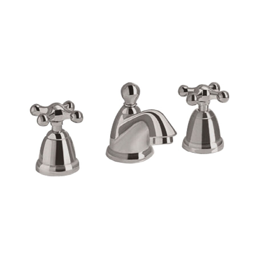
ENFIELD
Spread Lavatory Faucet
with the Speed Connect™ Drain
Congratulations on purchasing your American Standard
faucet with Speed Connect drain, a feature found only on
American Standard faucets.
Speed Connect™ Drain*
• Fewer parts, installs in less time
• Never needs adjustment
• Guaranteed to seal properly the first time, every time.
*Your new American Standard faucet is designed to work only with the Speed Connect drain.
To ensure that your installation proceeds smoothly-please read these instructions carefully before you begin.
Recommended tools
Screwdriver
1
INSTALL SPOUT
Insert SPOUT (1) and CABLE CONNECTOR (14) through center hole, making sure
the SPOUT ESCUTCHEON (2) and SEAL WASHER (3) are properly seated.
Assemble RUBBER WASHER (4), BRASS WASHER (5) and LOCKNUT (6) onto SPOUT
SHANK (7) from under side of sink . Make sure SPOUT (1) is centered in the mounting
hole and the slot in the BRASS WASHER (5) faces toward the rear of the sink.
Tighten Locknut (6) firmly. Fig. A.
1A
INSTALL VALVE BODY
Place RUBBER RING (9) into DECK ADAPTER (10).
Install LOCKNUT (11) and RUBBER WASHER (12) onto VALVE BODY (13).
From under side of mounting surface, install VALVE BODY (13) through valve
mounting holes. Threads of VALVE BODY (13) should extent at least 5/16
of a inch above mounting surface top. Fig. B. Thread DECK ADAPTER (10)
onto VALVE BODY (13) until snug against internal stop. If necessary, adjust
LOCKNUT (11).
Tighten LOCKNUT (11) with WRENCH (8) (supplied) to secure VALVE
BODY (13). Repeat above steps for opposite VALVE BODY (13A).
10
9
5/16'' MIN.
Fig. B.
8
Channel Locks
Turn off hot and cold water
CAUTION
supplies before beginning.
MOUNTING
SURFACE
12
11
13
Installation
Instructions
2373.801
2373.821
Adjustable Wrench
1
10
9
12
11
13
1
Certified to comply with ANSI A112.18.1
M 9 6 8 3 0 1 R e v. 1 . 3
Tubing Cutter
Fig. A.
2
3
SLOT
13a
1
7
4
5
6
14
Advertisement
Table of Contents

Subscribe to Our Youtube Channel
Related Manuals for American Standard Enfield 2373.821


Summary of Contents for American Standard Enfield 2373.821
- Page 1 • Never needs adjustment • Guaranteed to seal properly the first time, every time. *Your new American Standard faucet is designed to work only with the Speed Connect drain. To ensure that your installation proceeds smoothly-please read these instructions carefully before you begin.
- Page 2 POP-UP DRAIN Remove CLEAR PLASTIC COVER (1). Remove CARDBOARD SPACER (2) from under DRAIN POP-UP (3). Tighten TAILPIECE (4) on DRAIN BODY before installing DRAIN BODY. Fig. B. REMOVE FLANGE Thread FLANGE (1) counter-clockwise and remove FLANGE (1) and FOAM GASKET (2) from drain body.
- Page 3 ATTACH CABLE CONNECTOR Thread CABLE CONNECTOR (1) clockwise onto DRAIN BODY CONNECTION (2) and hand tighten. Fig. A. Your new POP-UP DRAIN installation is now complete. Fig. B. Note: Tailpeice on pop-up drain is 1-1/4” O.D. Fig. B. CHECK OPERATION OF POP-UP Operate LIFT KNOB (1) to verify that STOPPER (2) opens and closes.
- Page 4 INSTALL HANDLES Push ADAPTER (1) on VALVE STEM (2), so that the hole of the ADAPTER (1) without a spline is facing up. See figure "A". Tighten STEM SCREW (3) to secure ADAPTER (1). Find correct position of LEVER HANDLE ASSEMBLY (4) or CROSS HANDE ASSEMBLY (5) by adjusting male teeth on ADAPTER (1) to female teeth in HANDLE (4, 5).
-
Page 5: Troubleshooting Guide
Speed Connect™ Drain Troubleshooting Guide If sink does not hold water even though Stopper is in the “down” position: • Follow CABLE ADJUSTMENT PROCEDURE. If Stopper does not raise up fully or sink drains too slowly: • Follow CABLE ADJUSTMENT PROCEDURE. If you need to remove the Stopper: •... - Page 6 To install the stopper in “Unlocked” mode, insert the Stopper into the Drain so that the Plastic Loop is facing toward the front of the Sink and the American Standard logo is facing rear. Rotate Stopper slightly if necessary so that the Stopper slides all the way down.
Need help?
Do you have a question about the Enfield 2373.821 and is the answer not in the manual?
Questions and answers
I am trying to replace the cartridge and I am having trouble removing the handle assemble. I was able to unscrew the base but unable to pull it off.
To remove the handle assembly on an American Standard Enfield 2373.821 to replace the cartridge, follow these steps:
1. Pull the handle assembly off the valve stem (3).
2. Remove the spring clip (4).
3. Lift off the stop washer (5).
This will expose the internal cartridge for replacement.
This answer is automatically generated