Advertisement
Table of Contents
- 1 Receiver Setup
- 2 Transmitter Setup
- 3 Operating the System
- 4 System Features
- 5 System Types
- 6 System Components
- 7 Transmitter Battery Installation
- 8 Tips for Achieving Maximum Performance
- 9 Troubleshooting
- 10 System Specifications
- 11 Battery Life
- 12 Licensing Information
- 13 Warranty Information
- Download this manual
Advertisement
Table of Contents

Subscribe to Our Youtube Channel
Related Manuals for Shure UNF Wireless system


Summary of Contents for Shure UNF Wireless system
-
Page 2: Receiver Setup
ENGLISH THE TWO MINUTE USER’S GUIDE 2:00 The instructions on this page will help you get your UT Series system up and running in minutes. For more detailed instructions, read the section of this manual that applies to your system. RECEIVER SETUP 1. -
Page 3: System Features
Your new UT Series system is designed to give you the best of both sound reinforce- ment worlds: the freedom of a wireless system, and the reliability of world-famous Shure sound quality. This manual covers each of the UT Series systems: The Vocal Artist-UHF, The Presenter-UHF, The Headset-UHF, and The Guitarist-UHF. -
Page 4: System Types
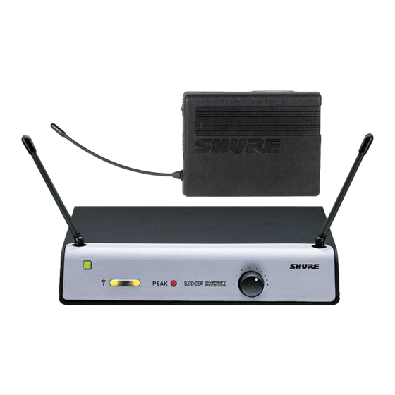
May be used with brass or woodwind instru- ments, with optional WM98 instrument microphone and mount. The Guitarist pro- vides the freedom of going wireless and the reliability of high quality Shure sound. SYSTEM COMPONENTS... - Page 5 ENGLISH SHURE BOTHERS INC. EVANSTON IL 60202 USA UNBALANCED HIGH Z SQUELCH UT4 DIVERSTIY RECEIVER LINE MIC BALANCED 12–18 VDC LOW Z MIN MAX FIGURE 2 UT4 DIVERSITY RECEIVER FEATURES (FIGURE 2) 1. Power On Indicator: This green light glows when the receiver is plugged into an electrical outlet.
- Page 6 5. Input Connector: Miniature connector (TB4M) allows connection to a variety of la- valier and headset microphone cables and the Shure WA302 instrument adapter cable. 6. Belt Clip: Secures the transmitter to a belt, waistband or guitar strap.
- Page 7 ENGLISH ATTACHING THE UT1 BODY-PACK TRANSMITTER TO BELT OR GUITAR STRAP FIGURE 4 1. Depress the tab marked PRESS and slip your belt, waist band or guitar strap be- tween the transmitter body and the belt clip (Figure 4). 2. The clip holds tighter if the material is drawn to the clip’s top wire, especially when using thinner guitar straps.
-
Page 8: Transmitter Battery Installation
ENGLISH TRANSMITTER BATTERY INSTALLATION 1. Slide the transmitter POWER/OFF switch to the OFF position. 2. Body-Pack: Press down on the OPEN side of the battery compartment cover, slide it back and flip it open, as shown in Figure 6A. 3. Hand-Held: Unscrew the transmitter battery cover to expose the battery termi- nals, as shown in Figure 6B. - Page 9 Transmitter Audio Gain Adjustment section. Then, If the system is still not op- erating properly, consult the Troubleshooting table. 6. When the performance is over, turn off the sound system and slide the transmit- ter’s POWER/OFF switch to the OFF position to conserve battery power. SHURE BACK FRONT FIGURE 8...
- Page 10 Audio Gain Adjustment section. If the system is still not operating properly, consult the Troubleshooting table. 7. When the presentation is over, turn off the sound system and slide the recessed transmitter POWER/OFF switch to the OFF position to conserve battery power. WL93 shown SHURE FRONT BACK FIGURE 9...
- Page 11 7. When headset is not in use, turn off sound system and slide the recessed trans- mitter POWER/OFF switch to the OFF position to conserve battery power. È È Í È È È È È È SHURE BACK FRONT FIGURE 10...
- Page 12 8. When the performance is over, turn off the amplifier and slide the recessed trans- mitter POWER/OFF switch to the OFF position to conserve battery power. SHURE Ì Ì Ì Ì Ì Ì Ì Ì Ì Ì Ì Ì Ì Ì Ì Ì Ì Ì...
- Page 13 ENGLISH RECEIVER VOLUME ADJUSTMENT FOR THE GUITARIST-UHF Follow these directions to adjust the volume control of the UT4 receiver, so that the wireless output of an instrument is equivalent to the output of a cabled instrument. 1. Plug instrument directly into guitar/bass amp. Set volume and tone controls on both the instrument and amplifier for a clean signal with desired tonal quality and volume.
-
Page 14: Tips For Achieving Maximum Performance
ENGLISH To return audio gain to the factory setting, rotate the transmitter audio gain control to the mid position and, on the body-pack only, slide the input attenuation switch to the 0 dB position. BODY-PACK AUDIO GAIN AND ATTENUATION SETTINGS The attenuation switch and the gain control on the UT1 body-pack are designed to be used in conjunction to provide a wide spectrum of gain control choices. -
Page 15: Troubleshooting
ENGLISH TROUBLESHOOTING PROBLEM INDICATOR STATUS SOLUTION No sound. Green transmitter POWER Slide transmitter POWER ON/OFF switch to ON posi- light off. tion. Make sure battery is inserted properly, observing battery polarity (“+/–”). If battery is inserted properly, replace with fresh battery. No sound. - Page 16 ENGLISH UT1 BODY-PACK TRANSMITTER SPECIFICATIONS RF Output 15 mW Typical Input Configuration Unbalanced Connector Type 4-pin Miniature connector (male), TB4M Actual Impedance Connector Pin Pin 1: Ground Pin 2: +5 V Bias Assignments Pin 3: Audio In Pin 4: 20k Resistor to Audio Ground Dimensions 82.6 mm H x 63.5 mm W x 26.2 mm D...
- Page 17 EMC Standard 301 489 Parts 1 and 9. Power supply meets Low Voltage Directive: 73/23/EEC. Shure Models UT1 and UT2 Transmitters meet the essential requirements of the European R&TTE Directive 99/5/EC and are eligible to carry the CE marking.
-
Page 18: Licensing Information
IMPORTANT: Licensing of Shure wireless microphone equipment is the user’s re- sponsibility, and licensability depends on the user’s classification and applica- tion, and on the selected frequency. Shure strongly urges the user to contact the ap- propriate telecommunications authority concerning proper licensing, and before choosing and ordering frequencies. - Page 19 TABLE 1 TABLEAU 1 TABELLE 1 TABLA 1 TABELLA 1 Country Code UT1, UT2 Code de Pays (595 – 865 MHZ) Lander–Kurzel Codigo de Pais Codice del Paese 595 – 865 MHZ * 595 – 865 MHZ * 595 – 865 MHZ * 595 –...
- Page 21 Patent Notice: Des 404,736 Shure Incorporated 222 Hartrey Avenue Evanston, Illinois 60202–3696 Phone: 847–866–2200 Fax: 847–866–2279 Web Address: http://www.shure.com Europe, Phone: 49–7131–72140 Fax: 49–7131–72141 Outside Europe and the U.S., Phone: 847–866–2200 Fax: 847–866–2585 27D8692 Copyright 2002, Shure Incorporated (BG) Printed in U.S.A.
Need help?
Do you have a question about the UNF Wireless system and is the answer not in the manual?
Questions and answers