
Related Manuals for Rane MS1S


Summary of Contents for Rane MS1S
-
Page 1: Table Of Contents
MS1S MIC STAGE Contents Important Safety Instructions Features General Description Application Information Features and Specifications Block Diagram Architectural Specifications Unit Dimensions Sound System Interconnection Layout and Schematic Warranty Declaration of Conformity 21591... -
Page 2: Important Safety Instructions
• Consult the dealer or an experienced radio/TV technician for help. CAUTION: Changes or modifications not expressly approved by Rane Corporation could void the user's authority to operate the equipment. This Class B digital apparatus complies with Canadian ICES-003. - Page 3 11. Only use attachments and accessories specified by Rane. 12. Use only with the cart, stand, tripod, bracket, or table specified by the manufacturer, or sold with the apparatus. When a cart is used, use caution when moving the cart/apparatus combination to avoid injury from tip-over.
-
Page 4: Features
Of course, for all of that extra money you receive a proportional increase in KPSI (knobs per square inch). The MS1S replaced the MS 1B Mic Stage with a new internal universal power supply. The width increases by one inch, all other features are the same. -
Page 5: Application Information
Uses and applications for the MS1S should be obvious. But then again, it’s ob- vious to us our taxes are too high and nothing is being done about that. With this in mind, perhaps a few words on using the MS1S might not be wasted. BALANCED USE The MS1S provides a true cross-coupled balanced output. -
Page 6: Features And Specifications
Features and Specifications Parameter Specification Input Impedance Gain Range 15 to 60 Phantom Power ..Impedance 6.81k Max. Input Level +9 / -35 Equivalent Input Noise -127 Signal to Noise Ratio Dynamic Range 114 / 91 CMRR Frequency Response 3 to 200k THD+Noise (gain 60 dB) .004 (Output=+20 dBu) THD+Noise (gain 15 dB) - Page 7 Limit Units Conditions/Comments Ω Balanced typ. 10 mA max. Ω Each leg min. Gain 15 / 60, balanced output typ. 20 kHz BW, Rs=150 Ω, Gain = 60 dB typ. 20 kHz BW, Rs=150 Ω, Gain = 15 dB, re 4 dBu typ.
-
Page 8: Block Diagram
66 dB adjustment range. Power, system signal and overload indicators shall be provided. High current cross-coupled active output line driver shall be standard, as well as input RFI filter protection. The unit shall be a Rane MS1S Microphone Stage. All features & specifications subject to change without notice. -
Page 9: Unit Dimensions
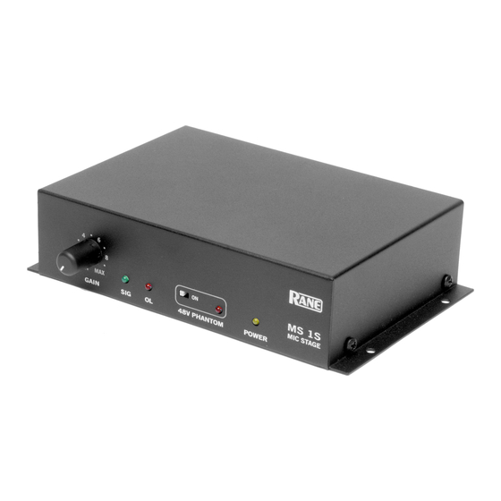
Unit Dimensions 6.1" MS1S MIC STAGE GAIN 48V PHANTOM POWER 0.15" 0.35" 6.8" MS1S PIN 2: (+) 100-240 V PIN 3: (–) PIN 1: 50/60 Hz 3 WATTS MADE IN U.S.A. RANE CORP. NORMAL INVERT POWER POLARITY LINE OUT MIC IN... -
Page 10: Sound System Interconnection
• Cause & prevention of ground loops • Interfacing balanced & unbalanced • Proper pin connections and wiring • Chassis ground vs. signal ground • Ground lift switches Rane Technical Staff RaneNote 110 © 1985, 1995, 2006, 2007, 2011 Rane Corporation... - Page 11 —Grounding and EMC practices — Shields of connectors in audio equipment containing active circuitry.” Rane’s policy is to accommodate rather than dictate. However, this docu- ment contains suggestions for external wiring changes that should ideally only be implemented by trained technical personnel. Safety regulations require that all original grounding means provided from the factory be left intact for safe operation.
-
Page 12: Ground Loops
Ground Loops Almost all cases of noise can be traced directly to ground loops, grounding or lack thereof. It is important to understand the mechanism that causes ground- ing noise in order to effectively eliminate it. Each component of a sound system produces its own ground internally. - Page 13 This is the right way to do it. So why doesn’t audio equipment come wired this way? Well, some does, and since 1993, more of it does. That’s when Rane started manufacturing some of its products with balanced inputs and outputs tying pin 1 to chassis.
- Page 15 See Figure 2. Many manufacturers provide several tools for this task, including Rane. Consult your audio dealer to explore the options available. The goal of these adaptors is to allow the use of standard cables. With these transformer isolation boxes, modification of cable assemblies is unnecessary.
- Page 16 The Last Best Right Way To Do It If transformer isolation is not an option, special cable assemblies are a last resort. The key here is to prevent the shield currents from flowing into a unit whose grounding scheme creates ground loops (hum) in the audio path (i.e., most audio equipment).
- Page 17 (Rane always provides this chassis point as an external screw with a toothed washer.) Any device with a 3-prong AC plug, such as an amplifier, may serve as an earth ground point.
- Page 18 Floating, Pseudo, and Quasi-Balancing During inspection, you may run across a ¼" output called floating unbal- anced, sometimes also called psuedo-balanced or quasi-balanced. In this configuration, the sleeve of the output stage is not connected inside the unit and the ring is connected (usually through a small resistor) to the audio signal ground.
- Page 19 Conference: Audio Test & Measurement, Portland, OR, May 1992, pp. 82- 92 (Audio Engineering Society, New York, 1992). 8. Macatee, RaneNote: “Grounding and Shielding Audio Devices,” Rane Corporation, 1994. 9. Philip Giddings, “Grounding and Shielding for Sound and Video,” S&VC, Sept.
- Page 20 Output From From Output...
- Page 21 Output From From Output...
- Page 22 To Input nput Output From Output...
- Page 23 To Input From From Output...
- Page 24 To Input Input Output From Output...
- Page 25 To Input From From Output...
-
Page 27: Layout And Schematic
Layout and Schematic... - Page 28 INPUT GAIN 0.0033 10.0k 2kRD 1512 2.67k 5.10 G2 V+ 2200pF 22.0 47/50v 0.0033 MBRS3100 MBRS3100 10.0k IEC PWR T 1A 250V 27.0 DF06M 1000uH P6SMB160AT MURS160 0.0022 X1Y2 1.50k 1.50k 6.8/400v 6.8/400v 0.0022 X1Y2 1000uH 2/6/2012 Main C:\CAD Projects\MS1S\MS1S-1.SchDoc...
- Page 29 10.0k 5.11k 4.75k 10.0k 5817 5.11k 100k 1/50v 51.1 POLARITY MBRS3100 MBRS3100 22/16v 1646 2P2T 22.0 3pin MALE XLR NORM SNS+ LINE OUT+ 2200pF OUT- OUTPUT SNS- 2P2T 511k 22.0 22/16v NORM MBRS3100 MBRS3100 2200pF 1SMB15CAT3 2P2T 0.001 X1Y1 10uH MURS160 22/63v 22/63v...
-
Page 30: Warranty
1) arising out of material or workmanship not provided or furnished by Rane, or 2) resulting from abnormal use of the product or use in violation of instructions, or 3) in products repaired or serviced by other than authorized Rane repair facilities, or 4) in products with removed or defaced serial numbers, or 5) in components or parts or products expressly warranted by another manufacturer. - Page 31 Rane warranty repair facility in the country where purchased, or to the Rane factory in the U.S., in the original packaging or a replacement supplied by Rane, with all transportation costs and full insurance paid each way by the purchaser or owner.
- Page 32 Warranty from 2 years to 3 years! TO VALIDATE YOUR EXTENDED WARRANTY Use the postcard that came in the box with your unit, or go to www.rane.com and click on New Product Registration. Fill out the warranty completely, being sure to include the model and serial number of the unit since this is how warranties are tracked.
- Page 33 FACTORY SERVICE If you wish your Rane product to be serviced at the factory, it must be shipped fully insured, in the original packing box or equivalent. This warranty will not cover repairs on products damaged through improper packaging. If possible, avoid sending products through the U.S.
- Page 36 MS1S MIC STAGE...
Need help?
Do you have a question about the MS1S and is the answer not in the manual?
Questions and answers