Table of Contents
Advertisement
Advertisement
Table of Contents

Related Manuals for Sekonic DUALMASTER L-558 CINE


Summary of Contents for Sekonic DUALMASTER L-558 CINE
- Page 1 DUALMASTER L-558/L-558 Operating Manual...
- Page 2 Blank page...
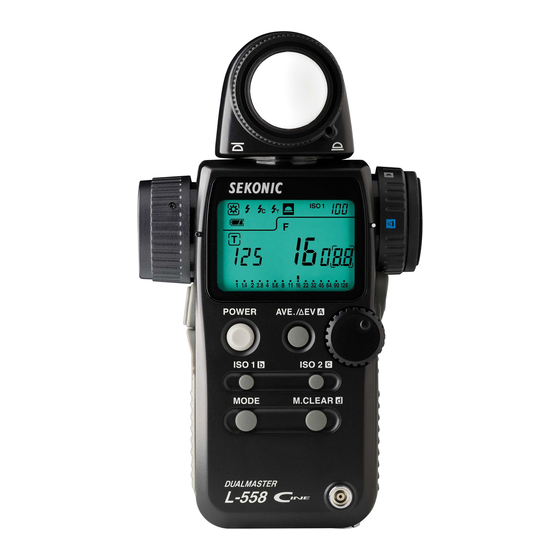
- Page 3 Exposure Meter The DUALMASTER L-558/L-558CINE is the latest addition to the extensive line of Sekonic Exposure Meters, which have been market leaders for over 50 years. The DUALMASTER was designed to offer more of what today’s photographer needs, and less of what they don’t. It offers flash and ambient exposure metering in both spot and incident modes.
-
Page 4: Table Of Contents
Table of Contents Parts Designation ........................ 1 Explanation of the Liquid Crystal Display (LCD) ..............2-4 Before Using ........................5-7 Attach the strap ......................5 Inserting the battery ....................5 Checking battery capacity ..................5 Replacing battery during measurement or when using the memory function ................6 Auto Power Off function ..................... -
Page 5: Parts Designation
1. Parts Designation q Lumisphere retracting ring w Lumisphere e Liquid Crystal Display (LCD) @4 Spot Lens Protective Glass @ 2 Eyepiece (with Diopter Adjustment) r Average / EV (Brightness Difference) u Memory button button (“A” in radio channel setting) t Jog Wheel !2 Power button y ISO 2 button (“c”... -
Page 6: Explanation Of The Liquid Crystal Display (Lcd)
2. Explanation of the Liquid Crystal Display ! 0 q L-558 L-558CINE ! 0 q NOTE: For explanation purposes, the display illustrated here shows all icons and readouts simultaneously. Actual display will never show as above. Auto Electro-Luminescent Display (EL) •... - Page 7 2. Explanation of the Liquid Crystal Display Display in viewfinder In setting : i Flash analyzing : r Luminance : (Only L-558CINE) q Measuring Mode Icons Ambient (see page 12) Auto-Reset Cordless Flash (see page 18) Cord Flash (see page 17) Wireless flash radio triggering mode (see page 34) w Incident / Reflected Spot Function Icons (see page 8) Appears when in Incident mode...
- Page 8 2. Explanation of the Liquid Crystal Display i Shutter priority indicator, shutter speed display for still photography or frames per second (f/s) for cinematography Appears when Shutter Priority (T) mode (see page 12) Appears when shutter speed is in minutes Appears when shutter speed is in full seconds Appears when cine speed is set in frames per second (see page 15) Appears when shutter angle is set to a value other than 180 degrees (558 CINE)(see...
-
Page 9: Before Using
3. Before Using Attach the strap Attach the Strap !9 by passing the small end loop through the eyelet o and passing the other end of strap through it. WARNING • Please place in a location where an infant cannot reach and accidentally get the strap wrapped around his or her neck. -
Page 10: Replacing Battery During Measurement Or When Using The Memory Function
3. Before Using Replacing battery during measurement or when using the memory function Always turn the power OFF before replacing batteries. If batteries are removed with the power ON, measurements and settings in memory can no longer be recalled. If after replacing the battery, or during measurements, strange screens (displays that have not been set) appear in the LCD, or nothing happens, no matter what button is pushed, remove the battery and wait at least ten seconds and then replace the battery. -
Page 11: Mode And Setting Lock Or Lock Off
3. Before Using Mode and Setting Lock or Lock Off 1. Hold down the Mode set button !0 and ISO1 button !1 and “LOC” will appear to indicate that the Settings are locked. The last measurement is held until the lock is released, even if the Jog wheel t is accidentally moved. -
Page 12: Basic Operation
4. Basic Operation Incident or reflected spot measuring To set for either incident or reflected light operation, turn the Incident / Reflected Spot Selector Dial @5 on the eye piece, to the desired position ( mark) until it clicks. Incident operation Reflected Spot operation When incident operation is selected, the mark will blink for three seconds and when Reflected... -
Page 13: Setting Measuring Mode
4. Basic Operation Setting measuring mode Hold down the Mode set button ! 0 and turn the Jog wheel t to select the desired mode. The mode switching sequence is shown in the chart below: MODE with Radio Shutter Speed Priority mode Wireless Multiple Flash transmitter module (Ambient light) -
Page 14: When Set For Incident Light
4. Basic Operation When set for incident light You can select extended or retracted lumisphere measuring positions by firmly rotating the lumisphere retracting ring (UP/DOWN) until it clicks into position. Retracted Lumisphere Extended Lumisphere (Lumidisc) When the Lumisphere is extended. (3-D Light Measurement) This is used to measure people, buildings, and other three dimensional objects. -
Page 15: When Set For Reflected Light (Spot Metering)
4. Basic Operation When set for reflected light (spot metering) This method measures the brightness (luminance) of the light reflected from the subject. It is useful for distant objects such as landscapes, when you cannot go to the position of the subject, or for metering subjects that generate light (neon signs, etc.), highly reflective surfaces or translucent subjects (stained glass, etc.). -
Page 16: Measurment
5. Measurement Measuring ambient light In this measurement mode, we have the choice of shutter priority mode, aperture priority mode and EV mode. Hold down the Mode set button !0 and turn the Jog wheel t to select ambient measurement mode 1-1 Shutter Speed Priority mode Hold down the Mode set button !0 and turn the... -
Page 17: Aperture Priority Mode
5. Measurement 1-2 Aperture Priority mode 1. Hold down the Mode set button !0 and turn the Jog wheel to select aperture priority mode 2. Turn the Jog wheel t to set the desired f stop value. MODE Measured value (shutter speed) 3. -
Page 18: Ev Mode
5. Measurement 1-3 EV mode 1. Hold down the Mode set button !0 and turn the Jog wheel t to select value mode. MODE Shutter 2. Press the Measuring button ! 4 to make a speed measurement. Release the Measuring button to complete the measurement. -
Page 19: Cinematography
5. Measurement 1-4 Cinematography 1. Hold down the Mode set button ! 0 and turn the Jog wheel t to select ambient light shutter speed priority mode MODE 2. Turn the Jog wheel to select the Cine Speed for the camera that will be used. - Page 20 5. Measurement * Example of correction value -1/3: Decrease ISO film speed by 1/3 stop, example: ISO 80 -1/3 stop = ISO 64 +1/3: Increase ISO film speed by 1/3 stop, example: ISO 80 +1/3 stop = ISO 100 Measured f stop 4.
-
Page 21: Measuring Flash Light
5. Measurement Measuring flash light This method of measurement can be done in the following modes; with cord, without cord, multiple flash with cord, multiple flash without cord and Wireless flash radio triggering mode (with optional radio transmitter module). When Measuring flash light, the shutter speed and F stop value (value combining ambient light and flash light: total amount of light) are displayed. -
Page 22: Auto Reset Cordless Flash Mode
5. Measurement WARNING • Please place in a location where an infant cannot reach and accidentally swallow the synchro terminal cap. There is danger of strangulation. CAUTION: • There is danger of electric shock if the meter is handled with wet hands, during rain, in areas splashed by water or where there is a lot of moisture, if you use cord synchronized flash. - Page 23 5. Measurement 3. When the Measuring button !4 is pressed, the mode mark will blink and the meter is ready to measure. The ready to measure mode will continue for approximately 90 seconds. During this time, trigger the flash to make a measurement.
-
Page 24: Cord Multiple Flash (Cumulative) Mode
5. Measurement 2-3 Cord multiple flash (cumulative) mode These measurements are used when the light generated by the flash is inadequate for proper exposure. The repeated flash pops can be accumulated until the desired aperture is displayed. The cumulative number is infinite. Only one digit is displayed if the cumulative number is ten or more. -
Page 25: Cordless Multiple Flash (Cumulative) Mode
5. Measurement CAUTION: • There is danger of electric shock if the meter is handled with wet hands, during rain, in areas splashed by water or where there is a lot of moisture. Under such conditions, it is recommended that you use the meter in the cordless flash mode, or wireless flash radio triggering mode and keep the Synchro terminal cap in place. - Page 26 5. Measurement 2. When the light from the flash is received, the measured value (f stop) is displayed. Each time this is repeated, the accumulated value for the aperture and the number of cumulative flashes is displayed. Perecentage of flash in total exposure 1/10 f stop Number of...
-
Page 27: Advanced Functions
6. Advanced Functions Memory function This meter can store up to nine measured values in memory for incident light and reflected light independently. This feature can be used in the following modes; Ambient light : shutter speed priority, aperture priority (L-558 only) or EV mode. Electronic Flash light : cord, cordless or wireless flash radio triggering mode. -
Page 28: Averaging Function
6. Advanced Functions Averaging function This function displays the average of up to nine of the values in memory. Press the Measuring button ! 4 a nd take a meas- urement. Press the Memory button u and store the measured value in memory. - Page 29 6. Advanced Functions Turn any secondary light source off. Point the Lumisphere toward the main light source, from the position of the subject and take a measurement. Press the Memory button u and store the value in memory. EV button r and display the “A”mark Press the AVE./ AVE./ EV on the LCD indicating a standard value.
-
Page 30: How To Use An Incident Illuminance (Lux Or Fc) Meter
6. Advanced Functions How to use an incident illuminance (LUX or FC) meter (L-558) Turn the Lumisphere retracting ring q to lower it to the mark position. Make sure that any compensation (see page 28) is canceled. Set the meter to EV mode and ISO 100. Place meter parallel to the subject and take a measurement. -
Page 31: How To Use A Reflected Luminance
6. Advanced Functions How to use a reflected luminance (cd/m or FL) meter (L-558) Make sure that any compensation (see page 28) is canceled. Set the meter to EV mode and ISO 100. Set meter to spot reading for reflected light. Take the measurement by looking through the finder and aligning so the subject that will be measured is inside the circle. -
Page 32: How To Use Exposure Compensation Function
6. Advanced Functions How to use the Exposure compensation function Exposure compensation can be made in precise 1/10 step increments in a +/- 9.9 EV range. Exposure compensation may be desired when requiring compensation for filters, bellows extension, etc. • M a k i n g a p l u s c o m p e n s a t i o n w i l l r e s u l t i n underexposing when taking a photograph. -
Page 33: How To Use Calibration Compensation Function
6. Advanced Functions How to use Calibration compensation function Calibration compensation can be made in precise 1/10 step increments in a +/- 1.0 EV. It may be desired to match specific requirements, calibration to other meters, etc. Set the measurement mode (incident light, reflected light) for the desired compensation. You can make calibration compensation independently for both incident, and reflected light. -
Page 34: Filter Compensation
6. Advanced Functions Filter compensation Filter compensation (1) It is possible to compensate for filter factory within a range of 5.0 EV in 1/10 steps. The measurement corresponding to the set compensation is displayed while pressing ISO2 button y. Select setting number 1 and item number 1 in the custom setting mode (refer to P32). Set the desired compensation by turning the Jog wheel t while pressing ISO2 button. -
Page 35: Flash Analyzing Function
6. Advanced Functions Flash analyzing function When measuring flash light, the shutter speed and F stop value (value combining ambient light and flash light: total amount of light) are displayed in the liquid crystal display and the ambient light and flash light are each displayed as separate values together with the total amount of light on the analog scale. -
Page 36: Custom Setting Function
6. Advanced Functions 10. Custom setting function It is possible to set the required functions in advance. CUSTOM SETTING LIST Item Model Lighting Custom Setting name Filter Ambient & ISO 2 setting Film — — compensation Flash Sensitivity 1/3 step 0.1EV step ( 5EV) Filter... - Page 37 6. Advanced Functions To enter the custom setting mode, the meter must first be turned off. Press Mode set button !0 and turn the power on. In the custom setting mode, ‘CS’ (custom setting) is displayed in the ISO display area, a setting number between 01-06 (558) or 01-09 (558 CINE) is displayed in the shutter speed display area and item Custom setting...
-
Page 38: Wireless Flash Radio Triggering System
6. Advanced Functions 11. Wireless Flash radio triggering With the radio transmitter module plugged into the meters radio socket and a receiver (RR-4 or RR- 32 sold separately, or PocketWizard® products; Classic, Plus, Max or MultiMax receivers) connected to one or more electronic flash units, the meter provides a convenient system that enables one person working alone to measure flash output without the need of a sync cord. - Page 39 6. Advanced Functions The set channel number will blink at this time. Turn the Jog wheel to set the channel setting. In the Setting mode, “ch” appears on the ISO display area. At the same time, channel numbers (1 to 16 and 17 to 32) appear on the F display area. When the channel number is 17 to 32, sub- channel (A, b, c and d) settings are displayed on the T indicator.
- Page 40 6. Advanced Functions Upon setting the channel and sub-channels, press Measuring button !4 to set radio triggering mode automatically, or the Wireless flash radio triggering mode or Wireless multiple flash radio triggering mode is selected using the Jog wheel while the Mode set button is pressed. For other settings of the measurement, see page 17.
-
Page 41: Accessories
7. Accessories Synchro cord (Sold separately) • This is a five-meter long cord with three plugs. An exposure meter, a camera, and a flash can all be connected at the same time. This is convenient when measurements are made, because it is not necessary to plug and unplug the synchro cord. -
Page 42: Accessories
7. Accessories Wireless flash radio triggering system (Sold separately) • Combining radio transmitter module (RT-32) with radio receiver (RR-32 or RR-4) enables measurements by triggering the flash from the exposure meter. Radio transmitter module (RT-32, 32 channels) Radio wave receiver Radio wave receiver (RR-32, 32 channels) (RR-4, 4 channels) -
Page 43: Technical Data
8. Technical Data · Type : Digital exposure meter for ambient and flash light · Light receiving method : Incident light and reflected light · Light Receptors Incident light : Convertible to flat diffuser (Lumisphere in down position) Reflected light : 1 spot with display in finder Metering distance 1m ~ ·... - Page 44 8. Technical Data : EV -9.9 to EV 46.6 (in 1/10 stop) Analog scale : (558) F1.0 - F128 (in 1/2 stop), T4.0 seconds -1/4000 seconds (in 1/2 stop) (558 CINE) F0.5 - F45 (in 1/3 stop) Shutter angle (558 Cine only) : 5 ~ 270 (in 5 stop), others: 144 , 172 Filter compensation : +/- 5.0 EV (in 1/10 stop)
-
Page 45: Safety Guide
9. Safety Guide WARNING: • Please keep in a location where an infant cannot reach and accidentally get the strap wrapped around his neck. There is danger of strangulation. • Never place batteries in fire, short, disassemble, or heat them. The batteries might break down, and cause injury or pollute the environment. -
Page 46: Care And Maintenance
Do not attempt to remove the rubber seal of the battery compartment cover. • If the rubber seal’s surface is damaged,water or moisture may enter and damage the meter. If this has happened, you must send your meter to the Sekonic Sevice Center in your country. - Page 47 FCC & IC compliance information: Warning: Changes or modifications to this unit not expressly approved by the party responsible for compliance could void the user's authority to operate the equipment. Note: This equipment has been tested and found to comply with the limits for a Class B digital device, pursuant To Part 15 of the FCC Rules.
- Page 48 7-24-14. Oizumi-Gakuen-cho, Nerima-ku, Tokyo 178-8686, Japan Phone:++81-3-3978-2335 Facsimile:++81-3-3978-5229 EU DECLARATION OF CONFORMITY THE EU DIRECTIVE COVERED BY THIS DECLARATION: Radio & Telecommunications Terminal Equipment Directive 1999/5/EC PRODUCT COVERED BY THIS DECLARATION: Name: DUALMASTER Model: L-558 / L-558CINE THE BASIS ON WHICH CONFORMITY IS BEING DECLARED: The DUALMASTER L558 / L-558CINE complies with the essential requirements of the Radio &...
- Page 49 Memo -45-...
- Page 50 Memo -46-...
- Page 51 Blank page...
- Page 52 7-24-14, OIZUMI-GAKUEN-CHO, NERIMA-KU, TOKYO 178-8686 JAPAN TEL:+81 ( 0 ) 3-3978-2335 FAX:+81 ( 0 ) 3-3978-5229 http://www.sekonic.co.jp/English JD1297560-01...
Need help?
Do you have a question about the DUALMASTER L-558 CINE and is the answer not in the manual?
Questions and answers