
Related Manuals for TL Audio 5001


Summary of Contents for TL Audio 5001
-
Page 1: User Manual
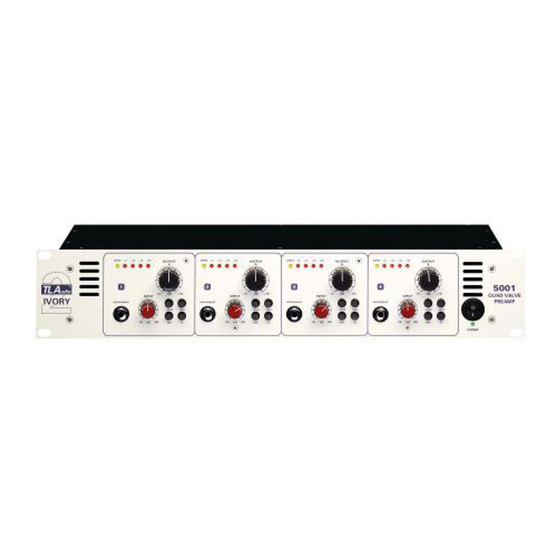
® udio user manual Ivory 2 Series 5001 QUAD VALVE PREAMP TL Audio Ltd, Letchworth, Herts, SG6 1AN, UK email: info@tlaudio.co.uk web: http://www.tlaudio.co.uk... -
Page 2: Table Of Contents
CONTENTS INTRODUCTION PRECAUTIONS INSTALLATION AC Mains Supply Audio Operating Level Microphone Inputs Instrument Inputs Balanced Outputs Unbalanced Outputs Ventilation Rear Panel OPERATION Front Panel Microphone Inputs 30dB Pad Phantom Power Input Gain Drive and Peak LEDs 90Hz Filter Phase Reverse Instrument Input 4.10 Output Level... -
Page 4: Introduction
The second stage of the 5001 consists of a twin triode valve (vacuum tube) circuit. The characteristic valve sound may be subtly introduced or used to effect by increasing the input gain. -
Page 5: Precautions
Please read this manual fully before installing or operating the 5001. PRECAUTIONS The TL Audio 5001 requires very little installation, but like all electrical equipment, care must be taken to ensure reliable, safe operation. The following points should always be observed:... -
Page 6: Installation
Audio Operating Level. The 5001 is equipped with outputs suitable for connection to a wide variety of other audio equipment. Generally, the balanced XLR connections will be required for interfacing to other professional equipment, where the operating... -
Page 7: Microphone Inputs
unbalanced jack connectors are generally intended for interfacing to semi- professional equipment and have an operating level of -10dBu, or about 225mV rms. Both outputs of each channel may be used simultaneously if required. Balanced interconnection is always preferable to obtain the best headroom and noise rejection, but can only be used if the other equipment in the chain - e.g. -
Page 8: Unbalanced Outputs
If used free standing, ensure that the equipment is protected against rain and spillage of liquid. The 5001 may be free standing, or mounted in a standard 19” rack. -
Page 9: 30Db Pad
The 4 XLR mic inputs are at the rear of the 5001. Virtually any low impedance professional microphone can be used. Condenser microphones will require the 48V phantom power to be engaged for correct operation, but before using Dynamic and Ribbon microphones ensure that the phantom power is switched off. -
Page 10: 90Hz Filter
gain is increased, over the range 0dB to +12dB: this should be accompanied by a ‘thickening’ and ‘warming’ of the audio signal, as more harmonic distortion is introduced. The red signal LEDs operate as a visual indication of output level, and are calibrated at +8dB, +12dB, +16dB and +20dB respectively, making them suitable for monitoring high level output signals such as those required to drive a digital recorder or soundcard. -
Page 11: 4.10 Output Level
4.11 Optional DO-4 Digital Output Card. The 5001 is designed to accept the optional D0-4 24 bit digital A to D converter card to allow easy interfacing of the 5001 with devices such as sound cards and digital recorders. - Page 12 SAMPLE RATE SELECTOR SWITCH (OPTIONAL)* DIGITAL OUTPUTS (OPTIONAL)* W/CLOCK INPUT (OPTIONAL)* SPDIF OUTPUT CAUTION WARNING - ATTENTION W/CLOCK Manufactured by TL Audio Limited, England. Ch 1+2 Ch 3+4 THIS APPARATUS MUST BE EARTHED. RISK OF ELECTRIC SHOCK DO NOT OPEN FOR CONTINUED PROTECTION...
-
Page 13: Getting Started
XLR output of the 5001 for maximum signal quality. Avoid connecting the line output of the 5001 to the microphone input of a console or soundcard - this could well result in level and impedance mismatches, with a resultant loss of... -
Page 14: Specifications
This variation in tone is one of the great strengths of the 5001 - you have the option of running it very clean, or nice and warm as you increase the valve drive. -
Page 15: Service
Crosstalk: Better than -70dB at 10KHz. (Mic inputs). Drive LED: Increasing intensity to reflect valve drive, commencing at +4dBu to full brightness at +14dBu (Output level control at 0dB). Level LEDs: Four LEDs, illuminating at +8dBu, +12dBu, +16dBu and +20dBu output level. Outputs: Balanced XLR, +4dBu nominal level. - Page 16 The manufacturer cannot accept responsibility for damage caused during transportation. The 5001 is supported by a limited warranty for a period of one year from the date of purchase. During this period, any faults due to defective materials or workmanship will be repaired free of charge.
Need help?
Do you have a question about the 5001 and is the answer not in the manual?
Questions and answers