
Related Manuals for TL Audio PA1


Summary of Contents for TL Audio PA1
-
Page 1: User Manual
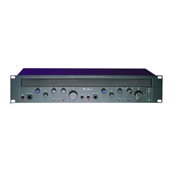
T L Audio User Manual PA1 PENTODE PRE-AMPLIFIER Tony Larking Professional Sales Limited, Letchworth, England. Tel: 01462 490600. International +44 1462 490600... - Page 2 INTRODUCTION The T L Audio Dual Pentode Pre-Amplifier is a very high quality, valve based microphone and instrument amplifier. Transformer coupled microphone inputs and front panel accessible instrument inputs are amplified by Pentode and Triode valve stages with variable gain and switchable HF and LF filters. The output levels are controlled by rotary faders, with headroom indicated by Signal, Peak and Clip LEDs.
-
Page 4: Installation
PRECAUTIONS The T L Audio Pentode Pre-Amplifier requires very little installation, but like all electrical equipment, care must be taken to ensure reliable, safe operation. The following points should always be observed: - All mains wiring should be installed and checked by a qualified electrician, - Ensure the correct operating voltage is selected on the rear panel before connecting to the mains supply,... - Page 5 Warning: attempted operation on the wrong voltage setting, or with an incorrect fuse, will invalidate the warranty. Audio Inputs. Each channel has a 3 pin XLR connector for the microphone input. It is compatible with either balanced or unbalanced signals, when the mating connector is appropriately wired: Balanced inputs: - Pin 1 = Ground (screen).
- Page 6 Outputs. The outputs are via balanced, 3 pin male XLR connectors. The mating connectors should be wired as follows: - Pin 1 = Ground (screen), - Pin 2 = Signal Phase (“+” or “hot”), - Pin 3 = Signal Non-Phase (“-” or “cold”). If an unbalanced output is required, pins 1 and 3 should both be connected to ground.
-
Page 8: Operation
OPERATION. Front Panel. The front panel controls are shown in fig.3. Input Stage. Ensure that the correct input connector, mic or instrument, is being used. Note that the instrument input will override the mic input if both are connected at the same time. +48V phantom power is available at the mic socket, selected by the switch adjacent to the input socket. - Page 9 Phase Reverse. Channel A features a phase reverse switch, which may be used to correct a phase error introduced elsewhere in a stereo signal path being processed by the Pre-Amplifier. A phase error typically appears as a loss of low frequency signal content, due to cancellation of out of phase components.
-
Page 11: Specifications
SPECIFICATIONS Mic Input: Transformer balanced, input impedance greater than 1K5ohm, to suit 150-600 ohm microphones. 48V phantom power available, via switch. Gain range +20 to +50dB. Noise (EIN): -122Bu at maximum gain with a 150 ohm termination, measured 22Hz-22KHz unweighted. Maximum input level +6dBu. - Page 12 Power Requirements: Rear panel selectable for 220-240V 50Hz or 110-120V 60Hz operation. Rear panel fuse 20mm, 1AT. Power consumption 30VA typical. Detachable 3 pin IEC connector, mating connector and cable supplied. Front panel On/Off switch with green LED. Dimensions: 19” rack mounting, 2U high. 483mm wide x 88mm high x 205mm deep.
Need help?
Do you have a question about the PA1 and is the answer not in the manual?
Questions and answers