Table of Contents
Advertisement
Model(s):
BCBV36 / BCBV36I
B-Vent Gas Appliance
• Important operating
a n d m a i n t e n a n c e
instructions included.
WARNING: If the information in these
instructions is not followed exactly, a fi re
or explosion may result causing property
damage, personal injury, or death.
• DO NOT store or use gasoline or other fl am-
mable vapors and liquids in the vicinity of this
or any other appliance.
• What to do if you smell gas
- DO NOT try to light any appliance.
- DO NOT touch any electrical switch. DO
NOT use any phone in your building.
- Immediately call your gas supplier from a
neighbor's phone. Follow the gas suppli-
er's instructions.
- If you cannot reach your gas supplier, call
the fi re department.
• Installation and service must be performed
by a qualifi ed installer, service agency, or the
gas supplier.
NOTICE
DO NOT DISCARD THIS MANUAL
• Read, understand and follow
these instructions for safe
installation and operation.
In the Commonwealth of Massachusetts installation must be
performed by a licensed plumber or gas fi tter.
A CO detector shall be installed in the room where the appliance
in installed.
Heatilator • BCBV36 • 4008-033 • Rev P • 8/12
Owner's Manual
Installation and Operation
• Leave this manual with
party responsible for use
and operation.
WARNING
HOT SURFACES!
Glass and other surfaces are hot during
operation AND cool down.
Hot glass will cause burns.
•
DO NOT touch glass until it is cooled
•
NEVER allow children to touch glass
•
Keep children away
•
CAREFULLY SUPERVISE children in same room as
fi replace.
•
Alert children and adults to hazards of high temperatures.
High temperatures may ignite clothing or other fl ammable
materials.
•
Keep clothing, furniture, draperies and other fl ammable
materials away.
Installation and service of this appliance should be
performed by qualifi ed personnel. Hearth & Home
Technologies suggests NFI certifi ed or factory trained
professionals, or technicians supervised by an NFI
certifi ed professional.
1
Advertisement
Table of Contents

Subscribe to Our Youtube Channel
Related Manuals for Heatilator BCBV36


Summary of Contents for Heatilator BCBV36
- Page 1 In the Commonwealth of Massachusetts installation must be gas supplier. performed by a licensed plumber or gas fi tter. A CO detector shall be installed in the room where the appliance in installed. Heatilator • BCBV36 • 4008-033 • Rev P • 8/12...
-
Page 2: Congratulations
DO NOT REMOVE OR COVER THIS LABEL. VENTED GAS FIREPLACE - NOT FOR USE WITH SOLID FUEL. FOYER À GAZ À ÉVACUATION - NE DOIT PAS ÊTRE UTILISÉ AVEC UN COMBUSTIBLE SOLIDE. Heatilator • BCBV36 • 4008-033 • Rev P • 8/12... -
Page 3: Table Of Contents
A. Appliance Dimension Diagram 7 Vent Information and Diagrams B. Service Parts List A. Vent Guidelines C. Optional Components B. Vent System Configuration D. Contact Information = Contains updated information. Heatilator • BCBV36 • 4008-033 • Rev P • 8/12... -
Page 4: B. Warranty
Limited 3 years Firebox and heat exchanger Lifetime All replacement parts 90 Days beyond warranty period See conditions, exclusions, and limitations on next page. 4021-645C 12-29-10 Page 1 of 2 Heatilator • BCBV36 • 4008-033 • Rev P • 8/12... - Page 5 THE EXTENT PROVIDED BY LAW, HHT MAKES NO EXPRESS WARRANTIES OTHER THAN THE WARRANTY SPECIFIED HEREIN. THE DURATION OF ANY IMPLIED WARRANTY IS LIMITED TO DURATION OF THE EXPRESSED WARRANTY SPECIFIED ABOVE. 4021-645C 12-29-10 Page 2 of 2 Heatilator • BCBV36 • 4008-033 • Rev P • 8/12...
-
Page 6: Listing And Code Approvals
A 110-120 VAC circuit for this product must be protected with ground-fault circuit-interrupter protection, in compliance with the applicable electrical codes, when it is installed in locations such as in bathrooms or near sinks. Heatilator • BCBV36 • 4008-033 • Rev P • 8/12... -
Page 7: User Guide
Closed Circulating Air Passageways Mantel Glass Doors Outside Air Kit (not shown) Section 2.E. High Limit Switch Grate Clear Space Hearth Section 2.D. (not required) Figure 2.1 General Operating Parts Heatilator • BCBV36 • 4008-033 • Rev P • 8/12... -
Page 8: Clear Space
• Install a switch lock or a wall/remote control with child protection lockout feature. • Keep remote controls out of reach of children. See your dealer if you have questions. Heatilator • BCBV36 • 4008-033 • Rev P • 8/12... -
Page 9: Lighting Instructions (Ipi)
* For U.S. only! NATURAL GAS Due to high surface temperatures, keep children, clothing and furniture away. Keep burner and control compartment clean. See installation and operating instructions accompanying the appliance. 33631D Heatilator • BCBV36 • 4008-033 • Rev P • 8/12... -
Page 10: Lighting Instructions (Standing Pilot)
For normal use, activate/deactivate your fireplace with the wall switch or remote control. • If your fireplace must be deactivated for service or an extended period of time, follow the instructions below. VENT Heatilator • BCBV36 • 4008-033 • Rev P • 8/12... -
Page 11: After Fireplace Is Lit
In an IntelliFire ignition system (IPI), the pilot flame should turn off when appliance is turned off. burn continually? Some optional control systems available with IPI models may allow pilot flame to remain lit. In a standing pilot system the pilot will always stay on. Heatilator • BCBV36 • 4008-033 • Rev P • 8/12... -
Page 12: Maintenance And Service
Clean glass with a non-abrasive commercially available cleaner. Light deposits: Use a soft cloth with soap and water Heavy deposits: Use commercial fireplace glass cleaner (consult with your dealer) • Reinstall door or decorative front. Heatilator • BCBV36 • 4008-033 • Rev P • 8/12... - Page 13 Check for smooth lighting and ignition carryover to all ports. Verify that there is no ignition delay. • Inspect for lifting or other flame problems. Figure 3.2 Standing Pilot Flame Patterns Heatilator • BCBV36 • 4008-033 • Rev P • 8/12...
-
Page 14: Installer Guide
Framing/Header in Ceiling Joists (SECTION 5) (SECTION 8) Optional Wall Switch Mantel & Mantel Leg (SECTION 13) Surround Hearth Extension (not required) Gas Line (SECTION 11) Figure 4.1 Typical System Heatilator • BCBV36 • 4008-033 • Rev P • 8/12... -
Page 15: Design And Installation Considerations
DO NOT use this appliance if any part has been under wa- ter. Call a qualified service technician to inspect the appli- ance and to replace any part of the control system and/or gas control which has been under water. Heatilator • BCBV36 • 4008-033 • Rev P • 8/12... -
Page 16: Negative Pressure
• Ensure adequate outdoor air is supplied for combustion appliances and exhaust equipment. Recommended Recommended Location Location Marginal Location Location Recommended Location Recommended Windward Leeward Multi-level Roofs Figure 4.2 Heatilator • BCBV36 • 4008-033 • Rev P • 8/12... -
Page 17: Framing And Clearances
The chase should not break the outside building envelope in any manner. Heatilator • BCBV36 • 4008-033 • Rev P • 8/12... -
Page 18: Clearances
(914 mm) Model Rough Opening Rough Opening Rough Opening (Width) (Height (Depth) BCBV36 39-3/4 in. 33-7/8 in. 19-1/4 in. (1010 mm) (860 mm) (489 mm) Figure 5.2 Clearances to Combustibles Heatilator • BCBV36 • 4008-033 • Rev P • 8/12... -
Page 19: Mantel And Wall Projections
1 in. (25 mm) min. to perpendicular wall 2-3/8 in. (60 mm) min. from fireplace opening to perpendicular wall Figure 5.4 Combustible Mantel Leg or Wall Projections (Accept- able on both sides of opening) Heatilator • BCBV36 • 4008-033 • Rev P • 8/12... -
Page 20: Termination Locations
Over 18/12 to 20/12 Over 10/12 to 11/12 3.25 Over 20/12 to 21/12 * 3 ft. minimum in snow regions Figure 6.1 Minimum Height From Roof To Lowest Discharge Opening Heatilator • BCBV36 • 4008-033 • Rev P • 8/12... -
Page 21: Vent Information And Diagrams
Note: 61° to 90° elbows are not allowed. Only 60° elbows or less are allowed. A straight section is not required before the first elbow. Figure 7.1 Vertical Termination Clearances Figure 7.3 Maximum Horizontal Run Heatilator • BCBV36 • 4008-033 • Rev P • 8/12... -
Page 22: Vent Clearances And Framing
2 in. (51 mm) above insulation. Attic shields must meet specified clearance and be se- cured in place. Use B-vent manufacturer’s firestops to provide adequate clearances. Heatilator • BCBV36 • 4008-033 • Rev P • 8/12... -
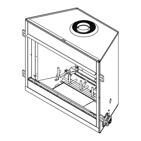
Page 23: Appliance Preparation
If applicable, ensure that gas and electrical connections are installed at this time. Refer to Sections 11 (Gas Infor- mation) and 12 (Electrical Information). Nailing Tabs (both sides) Figure 9.2 Proper Positioning and Securing of Appliance Heatilator • BCBV36 • 4008-033 • Rev P • 8/12... -
Page 24: Installing Vent Pipe
2 in. (51 mm) above insulation. Attic shields must meet vent manufacturer’s specified clearance and be secured in place per vent manufactur- er’s instructions. Figure 10.1 Attach Vent to Firebox Heatilator • BCBV36 • 4008-033 • Rev P • 8/12... -
Page 25: Gas Information
2000 feet and 4500 feet. Above 4500 feet, gas connector are connected to the 1/2 in. (13 mm) control consult local gas utility. valve inlet. • If substituting for these components, please consult local codes for compliance. Heatilator • BCBV36 • 4008-033 • Rev P • 8/12... -
Page 26: Electrical Information
• Wiring for optional Hearth & Home Technologies approved accessories should be done now to avoid reconstruction. Follow instructions that come with those accessories. Heatilator • BCBV36 • 4008-033 • Rev P • 8/12... -
Page 27: Electrical Service And Repair
Wall Switch Pilot Assembly Optional Remote Junction Limit Switch Adaptor GRN* * GRN wire only used with optional wall switch WSK-MLT-HTL Valve Figure 12.3 Intellifire Pilot Ignition (IPI) Wiring Diagram Heatilator • BCBV36 • 4008-033 • Rev P • 8/12... -
Page 28: Junction Box Installation
Figure 12.7 Attach the Heat Shield Slide the flanges of the junction box through the slots in the bracket. Figure 12.5 Position Bracket on Junction Box Figure 12.8 Attach the Junction Box Heatilator • BCBV36 • 4008-033 • Rev P • 8/12... -
Page 29: Finishing
1 in. (25 mm) min. to perpendicular wall 2-3/8 in. (60 mm) min. from fireplace opening to perpendicular wall Figure 13.2 Combustible Mantel Leg or Wall Projections (Accept- able on both sides of opening) Heatilator • BCBV36 • 4008-033 • Rev P • 8/12... -
Page 30: Appliance Setup
Place lava rock on top of control access panel in front of, under and around the burner. See Figure 14.3. Figure 14.1 Control Access Panel Shipping Location Figure 14.3 Placing the Lava Rock Figure 14.2 Control Access Panel Installation/Removal Heatilator • BCBV36 • 4008-033 • Rev P • 8/12... -
Page 31: Place The Vermiculite
Place rockwool the full length of the burner. • Do not pack tightly against the burner. Figure 14.7 Remove Grate/Log Assy. Figure 14.5 Placing the Rockwool Figure 14.8 Remove Screws Holding Back Log Heatilator • BCBV36 • 4008-033 • Rev P • 8/12... -
Page 32: Hood
Rotate the air shutter to the left to close. • Tighten the set screw. NOTICE: If sooting occurs, provide more air by opening the air shutter. Figure 14.10 Air Shutter Location Heatilator • BCBV36 • 4008-033 • Rev P • 8/12... -
Page 33: Troubleshooting
With the pilot in the ON position, disconnect the thermopile leads from the valve. Take a reading at the thermopile leads. The reading should be 350 millivolts minimum. Replace the thermopile if the reading is below the minimum. Heatilator • BCBV36 • 4008-033 • Rev P • 8/12... - Page 34 Ensure that no debris has been placed at the base of, or in the area of the air holes in the center of the base pan beneath the burner. Ensure that the glass is tightened properly on the unit, particularly on top corners. Heatilator • BCBV36 • 4008-033 • Rev P • 8/12...
-
Page 35: Intellifire Ignition System
Verify module is securely grounded to metal chassis of appliance. Module voltage output / Valve/ Verify battery voltage is at least 2.7 volts. Replace batteries if voltage Pilot solenoid ohms readings. is below 2.7. Heatilator • BCBV36 • 4008-033 • Rev P • 8/12... - Page 36 Shut off the appliance and the gas supply. Do not attempt to operate the appliance until it has been examined by a qualified service technician. Heatilator • BCBV36 • 4008-033 • Rev P • 8/12...
-
Page 37: Reference Materials
7 in. 6-1/4 in. (63 mm) (178 mm) (159 mm) 11-7/8 in. 11-7/8 in. 7-1/4 in. (302 mm) (302 mm) 10 in. (184 mm) (254 mm) Figure 16.1 Appliance Dimensions Heatilator • BCBV36 • 4008-033 • Rev P • 8/12... -
Page 38: Service Parts List
Heatilator • BCBV36 • 4008-033 • Rev P • 8/12... - Page 39 Heatilator • BCBV36 • 4008-033 • Rev P • 8/12...
- Page 40 Heatilator • BCBV36 • 4008-033 • Rev P • 8/12...
- Page 41 Wall Switch Kit Natural to Propane Gas Conversion Kit Conversion Kit SCKN-B SCKP-B Propane to Natural Gas Natural to Propane Gas Conversion Kit Conversion Kit Bifold Doors BCRK36 Refractory DM1036/DM1036B/DM1036S Heatilator • BCBV36 • 4008-033 • Rev P • 8/12...
-
Page 42: C. Optional Components
C. Optional Components (continued) 20 in. [508 mm] 17 in. [432 mm] 9-3/8 in. LDS-BV Decorative Shroud [238 mm] Catalog # 12-1/2 15-1/2 LDS-BV TCG375 Terra Cotta Cap See your Heatilator dealer for a complete listing of optional components. Heatilator • BCBV36 • 4008-033 • Rev P • 8/12... -
Page 43: Contact Information
6748942, 6769426, 6774802, 6796302, 6840261, 6848441, 6863064, 6866205, 6869278, 6875012, 6880275, 6908039, 6919884, D320652, D445174, D462436; (Canada) 1297749, 2195264, 2225408, 2313972; (Australia) 780250, 780403, 1418504 or other U.S. and foreign patents pending. Printed in U.S.A. - Copyright 2008 Heatilator • BCBV36 • 4008-033 • Rev P • 8/12...
Need help?
Do you have a question about the BCBV36 and is the answer not in the manual?
Questions and answers