Heatilator BIR36-B Installation Manual
Hide thumbs
Also See for BIR36-B:
- Installation manual (44 pages) ,
- Owner's manual (24 pages) ,
- Owner's manual (24 pages)
Table of Contents
Advertisement
Quick Links
INSTALLER: Leave this manual with party responsible for use and operation.
OWNER: Retain this manual for future reference.
NOTICE:
DO NOT discard this manual!
Model(s):
WOODBURNING FIREPLACE
Installation and service of this fi replace should be
performed by qualifi ed personnel. Hearth & Home
Technologies recommends NFI certifi ed profes-
sionals, or technicians supervised by an
NFI certifi ed professional.
Installation Manual
Installation and Fireplace Setup
Heatilator • Birmingham 36-B Installation Manual • 4059-709 • Rev H • 10/09/13
WARNING: If the information in these
instructions is not followed exactly, a fi re
or explosion may result causing property
damage, personal injury, or death.
• DO NOT store or use gasoline or other fl am-
mable vapors and liquids in the vicinity of this
or any other appliance.
• DO NOT overfi re. Overfi ring will void your
warranty.
• Comply with all minimum clearances to com-
bustibles as specifi ed. Failure to comply may
cause house fi re.
WARNING
HOT SURFACES!
Glass and other surfaces are hot during
operation AND cool down.
Hot glass will cause burns.
• DO NOT touch glass until it is cooled
• NEVER allow children to touch glass
• Keep children away
• CAREFULLY SUPERVISE children in same room as
fi replace.
• Alert children and adults to hazards of high temperatures.
High temperatures may ignite clothing or other fl ammable
materials.
• Keep clothing, furniture, draperies and other fl ammable
materials away.
WARNING
Fire Risk.
For use with solid wood fuel only.
Other fuels may overfi re and generate
poisonous gases (i.e. carbon monoxide).
1
Advertisement
Table of Contents

Subscribe to Our Youtube Channel
Related Manuals for Heatilator BIR36-B


Summary of Contents for Heatilator BIR36-B
-
Page 1: Woodburning Fireplace
High temperatures may ignite clothing or other fl ammable materials. • Keep clothing, furniture, draperies and other fl ammable WOODBURNING FIREPLACE materials away. WARNING Installation and service of this fi replace should be performed by qualifi ed personnel. Hearth & Home Fire Risk. Technologies recommends NFI certifi ed profes- For use with solid wood fuel only. sionals, or technicians supervised by an NFI certifi ed professional. Other fuels may overfi re and generate poisonous gases (i.e. carbon monoxide). Heatilator • Birmingham 36-B Installation Manual • 4059-709 • Rev H • 10/09/13... -
Page 2: Table Of Contents
5 Chimney Installation H. Wood Burning Inserts A. Typical Chimney System 9 Reference Materials B. Assemble Chimney Sections A. Chimney Components C. Install Chimney Air Kit B. Optional Components D. Secure Offset/Return E. Install Ceiling Firestops ► F. Install Attic Insulation Shield G. Roof Penetration H. Install Chase/Chase Top I. Termination Cap Requirements J. Install Termination Cap Heatilator • Birmingham 36-B Installation Manual • 4059-709 • Rev H • 10/09/13... - Page 3 Fireplace Setup Section 8 (Pg. 35) All packaging and protective materials removed. Molded brick panels installed correctly. Grate is properly installed. Firescreen installed properly. Optional doors properly installed. Manual bag and all of its contents are removed from the fireplace and given to the party responsible for use and operation. Hearth & Home Technologies recommends the following: • Photographing the installation and copying this checklist for your file. • That this checklist remain visible at all times on the fireplace until the installation is complete. Comments: Further description of the issues, who is responsible (Installer/Builder/Other Trades, etc.) and corrective action needed: Comments communicated to party responsible __________________________ by ______________________on _________ (Builder/Gen. Contractor) (Installer) (Date) 4059-711 • Rev C • 3-25-13 Heatilator • Birmingham 36-B Installation Manual • 4059-709 • Rev H • 10/09/13...
-
Page 4: Product Specific & Important Safety Information
Improper installation, adjustment, alteration, service or maintenance can cause injury or property damage. For assistance or additional information, consult a qualified installer, service agency or your dealer. Heatilator • Birmingham 36-B Installation Manual • 4059-709 • Rev H • 10/09/13... -
Page 5: Getting Started
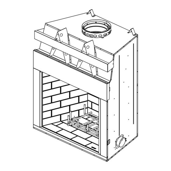
V-shaped standoffs (spacers) Mantel and surround Decorative facing and trim Hearth extension Outside Air Factory-built fireplace (both sides) Protective metal hearth strip(s) Figure 2.1 Typical Fireplace System Heatilator • Birmingham 36-B Installation Manual • 4059-709 • Rev H • 10/09/13... -
Page 6: Design And Installation Considerations
(1219 mm) MINIMUM Model # BIR36 47 7/8 89 1/8 44 5/8 20 3/8 63 1/8 28 1/2 1829 1216 2264 1133 1603 Figure 2.2 Fireplace Locations Heatilator • Birmingham 36-B Installation Manual • 4059-709 • Rev H • 10/09/13... -
Page 7: Locating Fireplace & Chimney
• Below adjacent structure Recommended: • Lower roof line • Insulated exterior chase • Avoid outside wall in cooler climates Windward Leeward Multi-level Roofs Figure 2.3 Recommended Chimney Locations Heatilator • Birmingham 36-B Installation Manual • 4059-709 • Rev H • 10/09/13... -
Page 8: Tools And Supplies Needed
• Vent system components and doors are shipped in separate packages. • Report to your dealer any parts damaged in shipment. • Read all the instructions before starting the installation. Follow these instructions carefully during the installation to ensure maximum safety and benefit. Heatilator • Birmingham 36-B Installation Manual • 4059-709 • Rev H • 10/09/13... -
Page 9: Framing And Clearances
(95 mm) 16 1/8 in. (129 mm) 11 1/8 in. (408 mm) 46 7/8 in. (282 mm) (1191 mm) 16 1/8 in. (408 mm) Figure 3.1 Fireplace Dimensions Heatilator • Birmingham 36-B Installation Manual • 4059-709 • Rev H • 10/09/13... -
Page 10: Clearances
1-1/2 in. (38 mm) to back & 1219 mm sides of appliance (except at nailing flanges 0 in. where it is 1/2 in. [13 mm]) to floor Figure 3.2 Clearances to Combustible Materials Heatilator • Birmingham 36-B Installation Manual • 4059-709 • Rev H • 10/09/13... -
Page 11: Construct The Chase
Chase Constructions shield should be installed in an insulated false ceiling at the 8 ft. (2438 mm) level above the fireplace assembly. This reduces heat loss through the chase. - In cold climates, the walls of the chase should be insulated to the level of the false ceiling as shown in Figure 3.3. This will help reduce heat loss from the home around the fireplace. Heatilator • Birmingham 36-B Installation Manual • 4059-709 • Rev H • 10/09/13... -
Page 12: Frame The Fireplace
* If interior of chase will be drywalled, add the thickness to this measurement. ** Adjust header height for raised floor under fireplace. Figure 3.5 Framing the Fireplace Heatilator • Birmingham 36-B Installation Manual • 4059-709 • Rev H • 10/09/13... -
Page 13: Secure And Level The Fireplace
Level the fireplace and shim as necessary. WARNING! Risk of Fire! Prevent contact with sagging, loose insulation. • DO NOT install against vapor barriers or exposed insulation. • Secure insulation and vapor barriers. • Provide minimum air space clearances at the sides and back of the fireplace assembly. Heatilator • Birmingham 36-B Installation Manual • 4059-709 • Rev H • 10/09/13... -
Page 14: Protective Metal Hearth Strips
Raised Platform instructions. 2 in. 1 in. (25 mm) min. (51 mm) overlap Floor 2 in. (51 mm) Figure 3.7 Protect the Front of an Elevated Platform Heatilator • Birmingham 36-B Installation Manual • 4059-709 • Rev H • 10/09/13... -
Page 15: Outside Air Kit
• Secure flex duct with metal tape, screws or wire ties. Figure 3.9 Outside Air Installation Heatilator • Birmingham 36-B Installation Manual • 4059-709 • Rev H • 10/09/13... -
Page 16: Chimney And Termination Requirements
18.5 ft (5.64 m) min. height single offset-return 74 1/8 in. 90 ft (27.4 m) (1884 mm) max. height Effective Height Figure 4.1 Chimney Requirements Heatilator • Birmingham 36-B Installation Manual • 4059-709 • Rev H • 10/09/13... -
Page 17: Offsets/Returns
33 3/4 67 3/4 1721 36 3/4 1854 39 3/4 1010 78 1/8 1984 41 1/8 1045 82 3/8 2092 45 3/4 1162 88 1/2 2248 48 1/8 1222 92 3/4 2356 51 3/4 1314 98 7/8 2511 Proper assembly of air cooled chimney parts results in an overlap of chimney joints of 1-1/4 in. (32 mm). Effective length is built into this table. Heatilator • Birmingham 36-B Installation Manual • 4059-709 • Rev H • 10/09/13... -
Page 18: Termination Requirements
In a staggered installation with both gas and wood terminations, the wood termination cap must be higher than the gas termination cap. Figure 4.3 Multiple Chimney Locations Heatilator • Birmingham 36-B Installation Manual • 4059-709 • Rev H • 10/09/13... -
Page 19: Chimney Installation
Attic shield movement Ceiling firestops are required where chimney passes through ceiling or floor Figure 5.1 Typical Chimney System - Guidelines for Chimney System Installation Heatilator • Birmingham 36-B Installation Manual • 4059-709 • Rev H • 10/09/13... -
Page 20: Assemble Chimney Sections
• Secure chimney returns with hanger straps provided; fasten to studs or joists. • Vertical straight runs of chimney must be supported every 35 ft (10.7 m). Figure 5.2 Assembling Chimney Sections WARNING! Risk of Fire! DO NOT install substitute or damaged chimney components. Heatilator • Birmingham 36-B Installation Manual • 4059-709 • Rev H • 10/09/13... -
Page 21: Secure Offset/Return
CAUTION! Risk of Fire! Ceiling firestops must be used whenever the chimney penetrates a ceiling/floor. • Chase construction requires ceiling firestops at each floor or every 10 ft. (3.05 m) of clear space. • The ceiling firestop slows spread of fire and reduces cold air infiltration. • Install a ceiling firestop whenever chimney penetrates ceiling/floor. • Mark and cut an opening in ceiling as shown in Figure 5.4. • Frame the opening with the same size lumber used in the ceiling joists. • Nail the ceiling firestop to the bottom of the ceiling joists when there is a room above. • Use an attic insulation shield if the ceiling is insulated. The ceiling firestop may then be attached above or below the joists. Heatilator • Birmingham 36-B Installation Manual • 4059-709 • Rev H • 10/09/13... -
Page 22: Install Attic Insulation Shield
Insulation Insulation Check each section by pulling up slightly from the top to ensure proper engagement before installing the suc- 13 in. Ceiling Firestop ceeding sections. If they have been connected correct- Pipe (330 mm) ly, they will not disengage when tested. Figure 5.7 Install Attic Insulation Shield (firestop below ceiling) Heatilator • Birmingham 36-B Installation Manual • 4059-709 • Rev H • 10/09/13... -
Page 23: Roof Penetration
WARNING! Risk of Fire! DO NOT caulk the pipe to the chase top collar. Turn-down • Caulk all seams to prevent leaks. Drip Edge Chase .018 (26 ga) min. Galvanized Chase Top Figure 5.9 Chase Top Construction Heatilator • Birmingham 36-B Installation Manual • 4059-709 • Rev H • 10/09/13... -
Page 24: Termination Cap Requirements
Termination cap pipe and chimney section must be snapped together to maintain an overlap of 1-1/2 in. (38 mm). Figure 5.10 Installing a TR11 & TR11-TV Round Termination Cap Heatilator • Birmingham 36-B Installation Manual • 4059-709 • Rev H • 10/09/13... - Page 25 Pipe Figure 5.13 Installing a TCT1175 Terra Cotta Cap Termination cap pipe and chimney section must overlap 1-1/2 in. (38 mm) Figure 5.14 Installing a DTO134/DTO146/DTS134/DTS146 Cap Heatilator • Birmingham 36-B Installation Manual • 4059-709 • Rev H • 10/09/13...
-
Page 26: Shrouds
3 in (76 mm) air space from bottom of shroud Chase Top to top of chase. Figure 6.3 Shroud & TR Series cap with no Radiation Shield Heatilator • Birmingham 36-B Installation Manual • 4059-709 • Rev H • 10/09/13... -
Page 27: Mailbox Style Shroud
Min. Base Dims. 34 x 34 Min. Opening Width 864 x 864 Min. Height Above Bottom of Termination Cap Min. Opening Width Min. Opening Height Figure 6.5 Roofed Style Shroud Dimensions Heatilator • Birmingham 36-B Installation Manual • 4059-709 • Rev H • 10/09/13... -
Page 28: Finishing
2 in. (51 mm) Figure 7.2 Decorative Facing Heatilator • Birmingham 36-B Installation Manual • 4059-709 • Rev H • 10/09/13... - Page 29 965 mm) to allow for door combustible sealant. installation. The surface of the finished hearth extension and the surface of the hearth panel should be level. Figure 7.3 Facing Materials and Mortar Heatilator • Birmingham 36-B Installation Manual • 4059-709 • Rev H • 10/09/13...
-
Page 30: Hearth Extension, Building And Finishing
USG Durock™ Cement Board 1.92 0.52 4 in. Cement Mortar 0.20 10 1/2 in. Common Brick 0.20 10 1/2 in. Ceramic Tile 12.50 0.08 25 3/4in. Armstrong™ Privacy Guard Plus 0.46 2.18 1 in. 14.3-20.0 0.07-0.05 29 1/2 - 41 1/4 in. Marble Heatilator • Birmingham 36-B Installation Manual • 4059-709 • Rev H • 10/09/13... -
Page 31: Fireplace Installed Flush On The Floor And Hearth Extension Raised To Bottom Of Firebox Opening
Figure 7.5 Hearth Extension Construction Noncombustible HX4 or Framing Material equivalent Figure 7.7 Raised Platform Hearth Extension-Framing Non-combustible Finishing Materials Figure 7.8 Raised Platform Hearth Extension-Finishing Heatilator • Birmingham 36-B Installation Manual • 4059-709 • Rev H • 10/09/13... -
Page 32: Raised Hearth Extension And Raised Fireplace
Non-combustible Floor and platform constructed of & 1/2 in. Durock Framing Material wood or other combustible material Figure 7.9 Raised Hearth Extension and Fireplace Framing Materials Heatilator • Birmingham 36-B Installation Manual • 4059-709 • Rev H • 10/09/13... -
Page 33: Fireplace Opening And Hearth Extension Flush With The Floor
WARNING! Risk of Fire! insulation Hearth & Home Technologies is not responsible for discoloration, cracking or other material failures of finishing materials due to heat exposure or smoke. Figure 7.10 Flush Hearth Extension Side View • Choose finishing materials carefully. Heatilator • Birmingham 36-B Installation Manual • 4059-709 • Rev H • 10/09/13... -
Page 34: Mantel And Wall Projections
1 1/2 in./38 mm maximum Measured from top of fireplace opening Seal joint with non-combustible sealant Figure 7.13 Mantel Specifications Heatilator • Birmingham 36-B Installation Manual • 4059-709 • Rev H • 10/09/13... -
Page 35: Fireplace Setup
Back Herringbone LH Herringbone Refractory LH Traditional Refractory Refractory Refractory Grate Grate Retainer Retainer Hearth Hearth Figure 8.1 Traditional Molded Brick Panel Figure 8.2 Herringbone Molded Brick Panel Heatilator • Birmingham 36-B Installation Manual • 4059-709 • Rev H • 10/09/13... -
Page 36: Install Screens
E. Install Mortar (Optional) The brick panels have been designed for installation without the use of mortar being necessary. If the look of mortar is preferred, it is available and can be installed. Follow the directions on the container for mixing. Clean sparingly as paint will rub off and may need to be touched up. Touch up paint is available as an accessory. Note: Herringbone refractory may require two buckets of mortar. The Traditional requires only one. F. Grate • Install the grate if a gas log set is not going to be installed. • Position the rear grate bar in the grate retainer. • Position the top of the grate retainer over the rear grate bar and fasten in place with screw provided. Heatilator • Birmingham 36-B Installation Manual • 4059-709 • Rev H • 10/09/13... -
Page 37: Gas Log/Lighter Provision
Improper installation of wood in- serts may cause fireplace or chimney system to overheat. If a wood burning insert is being installed in this fireplace, Gas Line Hearth & Home Technologies recommends full reline of Dimple the chimney. • Cooling air openings at the top of the chimney must not be obstructed in any manner. • Hearth & Home Technologies recommends securing the reline at the top of the flue and using the cap certified for use with this fireplace system. Gas Line Dimple Figure 8.5 Gas Line Dimples Heatilator • Birmingham 36-B Installation Manual • 4059-709 • Rev H • 10/09/13... -
Page 38: Reference Materials
DTS134 Short Square Decorative Cap (279 mm) DTS146 Tall Square Decorative Cap LDS33 Decorative Shroud - 3 ft x 3 ft (.91 m x .91 m) Outside Diameter LDS46 Decorative Shroud - 4 ft x 6 ft (1.22 m x 1.83 m) 13 in. (330 mm) LDS-BV Decorative Shroud - 26 in. x 26 in. (660 mm x 660 mm) Field Constructed Shrouds (See “Woodburning Termination Cap”) SL11 Chimney Stabilizer CT-11A Adapter-May be used with the following caps CT-Series DT-Series Heatilator • Birmingham 36-B Installation Manual • 4059-709 • Rev H • 10/09/13... - Page 39 RF570 Roof Flashing JB577 Chimney Joint Band 15-1/4in. (387 mm) 13 in. (330 mm) 28 in. 39-7/8 in. CB576 Chimney Joint Band (711 mm) (1013 mm) RF571 Roof Flashing Heatilator • Birmingham 36-B Installation Manual • 4059-709 • Rev H • 10/09/13...
- Page 40 ST1175 - Square Termination Cap 26 in. 20 in. (508 mm) CT11-A Adapter 17 in. (432 mm) 9-3/8 in. (238 mm) 10-1/4 in. (260 mm) TCT1175 - Terra Cotta Cap Heatilator • Birmingham 36-B Installation Manual • 4059-709 • Rev H • 10/09/13...
- Page 41 DTS134/DTS146 DTO134/DTO146 Decorative Caps DTO134 DTO146 22.7 1168 DTS134 21.18 DTS146 21.18 1168 Heatilator • Birmingham 36-B Installation Manual • 4059-709 • Rev H • 10/09/13...
-
Page 42: Optional Components
DFG4036 Series Glass Doors LDS-BV Decorative Shroud (optional) Catalog # DFS4036 Series Screen Doors (optional) 12.5 15.5 LDS-BV See your Heatilator dealer for a complete list of optional components. Heatilator • Birmingham 36-B Installation Manual • 4059-709 • Rev H • 10/09/13... - Page 43 This page intentionally left blank. Heatilator • Birmingham 36-B Installation Manual • 4059-709 • Rev H • 10/09/13...
- Page 44 Heatilator, a brand of Hearth & Home Technologies 7571 215th Street West, Lakeville, MN 55044 www.heatilator.com Please contact your Heatilator dealer with any questions or concerns. For the location of your nearest Heatilator dealer, please visit www.heatilator.com. Heatilator • Birmingham 36-B Installation Manual • 4059-709 • Rev H • 10/09/13...
Need help?
Do you have a question about the BIR36-B and is the answer not in the manual?
Questions and answers