Table of Contents
Advertisement
Advertisement
Table of Contents

Related Manuals for SPL 9945


Summary of Contents for SPL 9945
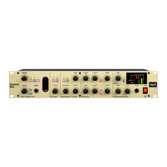
- Page 1 Manual Model 9945 Channel Strip...
- Page 2 SPL. Limitations of Liability: In no event will SPL be liable for any damages, including loss of data, lost profits, cost of cover or other special, incidental, consequential or indirect damages arising from the use of the unit, however caused and on any theory of liability.
-
Page 3: Table Of Contents
Contents Introduction ........................4 Principles ......................... 4 Hookup ..........................5 Connections: Rear front / Wiring ......................6 General advises / Connectors ..................7 Operation: • Preamplifier Microphone Gain, 48 Volt phantom power, phase reverse, high pass ... 9 Highpass, Instrument Gain, About levelling, Instr./Line On - MicOff, Instr. -
Page 4: Introduction
With Channel One SPL have produced a complete channel strip which for the greater part is based on the processing concepts already successfully realized in other products. The very complex task of a channel strip profits particularly from the innovative techniques that have always allowed the operation of SPL equipment to be efficient and objective. -
Page 5: Hookup
This leads, in the truest sense of the word ”clean” , to considerably improved tonal quality. The scatter free toroidal transformer, manufactured to SPL tolerances, supplies the equipment with the necessary voltages and forms the basis for a clean electrical supply to all parts of the circuitry. -
Page 6: Connections Rear Front / Wiring
Connections Rear Front / Wiring... -
Page 7: General Advises / Connectors
Connections General Advises Again, while Channel One’s housing is EMV-proof and protects against HF- interference, placement of the unit is very important since it amplifies micro- phone signals as well as other unwanted signals. Before connecting the Channel One or any other equipment turn off all power. Adjust the voltage setting on the back so that it corresponds with the power conditions. -
Page 8: Analog Outputs
Connections Connectors Analog Outputs The Analog Outputs deliver balanced output signals. Lundahl output trans- formers can be equipped optionally. Since both connectors are working in parallel, unbalancing one connector also unbalances the other one. If for example a mono jack plug is connected to the jack connector, the XLR connector is switched to unbalanced opera- tion as well. -
Page 9: Operation
Operation Pre-amplifier Microphone Gain The Microphone Gain control determines the preamplification of the micro- phone signal. The preamplification values extend up to + 65 dB. If Lundahl input transformers are fitted the scale values are to be increased by + 14 dB. Please refer to "About levelling"... -
Page 10: Highpass, Instrument Gain, About Levelling, Instr./Line On - Micoff, Instr. Input
Operation Pre-amplifier Highpass The Highpass filter is used to eliminate disturbing low frequencies. These disturbances could impair the following processing or AD conversion. The cut-off frequency at 50 Hz avoids influences to vocals. The roll-off is 12 dB/octave. Instrument Gain The Instrument Gain control determines the preamplification of the inputs Line and Instrument. -
Page 11: De-Esser
Operation De-Esser The first module behind the pre-amplifier stage is the De-Esser, which imme- diately removes disturbing S-sounds when required. The De-Esser module is activated when the button is on. The S-Detect. LED in the display will show that S-sounds are being detected regardless of the selected S-Reduction value, in other words even when the button is switched off detection is still shown in the display. -
Page 12: Insert
Operation De-Esser A further specialty is the integrated auto-threshold-function which makes processing independent of the input level. Even when the speaker or singer does not maintain a constant distance to the microphone, processing is retained at the pre-set S-reduction value. Conventional systems are depen- dent on the input level and work more intensively as the distance to the microphone is reduced. -
Page 13: Limit, Gain Reduction, Noise Gate
Operation Compressor/Limiter Limit The Limit button switches the Compressor to limiter mode. The Gain Reduction control serves the purpose of controlling the threshold. The Limiter does not function as a peak limiter, in other words there is no guarantee that all peaks are intercepted. It is therefore advisable when modulating a subsequent unit that a headroom of 2 to 4 dB remains. -
Page 14: Make Up, Technical Information Regarding The Compressor/Limiter
Operation Compressor/Limiter Make Up With the Make Up control the level reduction caused by compression or limiting can be restored.With assistance of the Gain Reduction display in the display field setting the Make Up control is very easy: If the maximal reduc- tion value caused by the loudest tone amounts to -9 dB, for instance, the Make Up control is also to be set to the value +9 dB. -
Page 15: Equalizer
Operation Equalizer The On button inserts the Equalizer module into the signal path. Under normal circumstances the input signal comes from the compressor. With the Pre-comp button the Equalizer can be switched in before the Compressor/ Limiter so that the input signal is received from the De-Esser or Insert. Pre Comp. -
Page 16: Mid-Hi Band, Cut/Boost (Mid-Hi), Low Band, Cut/Boost (Low)
Operation Equalizer The ”soft” and natural tonal property, characteristic of the coil-capacitor filter, lends itself extremely well to provide clarity to vocals in the upper frequency range thereby improving their presence. On the other hand harsh sounds can be lent a more pleasant sound characteristic through damping. Mid-Hi Band The center frequency of the semi-parametric mid high frequency filter is set with the Mid-Hi Band control. -
Page 17: Tip For Frequency Setting, Distortion
Operation Equalizer The Low Band filter can be applied in many ways. Examples are; to accen- tuate the fundamental sound of a voice, to cut ”boom frequencies” and for placement of bass emphasized instruments such as bass guitar, bass drums- or synthesizers during recording or subsequently when mixing etc. -
Page 18: Output
Operation Output Output The outgoing signal can either be dampened to –20 dB or further amplified by +6 dB with the Output control to provide optimal drive to the subse- quent units or the optional AD/DA converter. The individually selected output level is shown on the PPM-Output display in the display field. -
Page 19: Headphone Monitor
Operation Headphone Monitor Playback The Playback control regulates the volume of the playback signal which is passed to the musician. There are two methods of passing the mono play- back signal: The first is to pass the music to both ear pieces of the head- phone in which case ”Playback Input Left”... -
Page 20: Displays
Operation Displays S-Detect. The S-Detect. LED shows when S-sounds have been detected. It is only active when the De-Esser is switched on and is independent from the selected S- Reduction setting. Clip The Clip LED shows overload in the unit. The clipping level of the LED lies approximately 2 dB below the internal full scale (conforms to + 19 dBu). -
Page 21: Gain Reduction, Ppm-Output
Operation Displays Gain Reduct. The Gain Reduct. display provides information about the processing being undertaken with the Compressor/Limiter or the Noise Gate.The level change, perhaps caused by compression, are scaled in 1.5 dB steps. The display is activated when the Compressor/Limiter module is switched on. Noise Gate operation is visible because all Gain Reduct. -
Page 22: Specifications
Specifications Measurements Microphone Input Frequency Response: ........10 Hz-100 kHz (100 kHz = -3 dB) Common Mode Rejection: ......1 kHz: -80 dB / 10 kHz: -78 dB (@ -20 dBu) THD & N: .............. Amplification: A weighted: 20 dB -97,1 dBu 40 dB -91,1 dBu... -
Page 23: Block Diagram
Block Diagram Channel One, Model 9945... -
Page 24: Measurements
Measurements Compressor/Limiter, Air Band Diagram 1 shows various curve characteristics for the Compressor/Limiter The reference curve A displays the relation between input and output. Curve B shows the curve characteristics of the Compressor. The soft knee characteristic is clearly visible. Curve C portrays the limiter’s curve characteristics. - Page 25 Measurements Mid-Hi filter, Low filter Diagram 3 displays various cut and boost settings of the Mid-Hi filter at 3 kHz. The proportional-Q characteristic is distinctly visible. Diagram 4 displays the curves of the Low Band filter. Various cut and boost- settings at 150 Hz.
-
Page 26: Warranty
It is possible that economic loss or injury to person or property may result from the failure of the product; however, even if SPL has been advised of this possibility, this limited warranty does not cover any such consequential or incidental damages. -
Page 27: Copy Master
Copy Master... -
Page 28: Notes
Manual Notes ......................................................................................................................................................................................................................................................................................................................................................................................................................................................................................................................................................................................................................................................................................................
Need help?
Do you have a question about the 9945 and is the answer not in the manual?
Questions and answers