Table of Contents
Advertisement
Advertisement
Table of Contents

Related Manuals for SoundCraft LIVE 8


Summary of Contents for SoundCraft LIVE 8
-
Page 1: User Guide
User Guide... - Page 2 Soundcraft shall not be liable for any loss or damage whatsoever arising from the use of information or any error contained in this manual.
-
Page 3: Table Of Contents
Contents IMPORTANT SAFETY INSTRUCTIONS SAFETY SYMBOL GUIDE Introduction Installation DPS-3 POWER SUPPLY MAINS INSTALLATION WORKING SAFELY WITH SOUND INTERNAL JUMPER SETTINGS AUDIO CONNECTOR PINOUTS TYPICAL CONNECTING LEADS DIMENSIONS Block Diagram Using The Console MONO INPUT CHANNEL STEREO INPUTS GROUP SECTION MASTER SECTION METERBRIDGE Applications... -
Page 4: Important Safety Instructions
IMPORTANT SAFETY INSTRUCTIONS Read these instructions. Keep these instructions. Heed all warnings. Follow all instructions. Do not use this apparatus near water. Clean only with a dry cloth. Do not block any ventilation openings. Install in accordance with the manufacturer’s instructions. Do not install near any heat sources such as radiators, heat registers, stoves, or other apparatus (including amplifiers) that produce heat. - Page 5 Note: It is recommended that all maintenance and service on the product should be carried out by Soundcraft or its authorised agents. Soundcraft cannot accept any liability whatsoever for any loss or damage caused by service, maintenance or repair by unauthorised personnel.
-
Page 6: Safety Symbol Guide
For your own safety and to avoid invalidation of the warranty please read this section carefully. SAFETY SYMBOL GUIDE For your own safety and to avoid invalidation of the warranty all text marked with these symbols should be read carefully. WARNINGS The lightning flash with arrowhead symbol, is intended to alert the user to the presence of un-... -
Page 7: Introduction
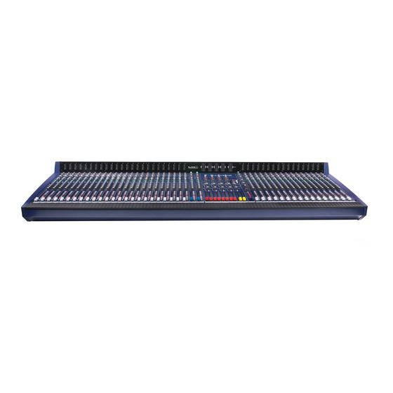
`feel’ and visual clarity complement the styling, resulting in a truly professional product which is ideal for both touring and fixed PA installations. LIVE 8 is available in 24, 32 & 40 channel frame sizes. All frame sizes incorporate removeable side cheeks to enable the console to be fitted compactly in a flight case. -
Page 8: Installation
Ensure that the DPS-3 power supply is NOT connected to the Mains and is turned OFF. The power supply can be positioned anywhere within reach of the LIVE 8 and an available power socket, but it is best rack-mounted in a position where airflow through the vents is not obstructed, and where the power switch or cables cannot be accidentally knocked. -
Page 9: Mains Installation
General Wiring Procedures To take full advantage of the excellent signal to noise ratio and low distortion of Soundcraft consoles, care must be taken to ensure that incorrect installation and wiring does not degrade the performance of the desk. Hum, buzz, instability and Radio Frequency interference can usually be traced to earth loops and inferior earthing systems. -
Page 10: Working Safely With Sound
Capacitive coupling between the screen and signal wires. To minimise the adverse affects of the unwanted coupling to the signal wires, it is important that the screen is connected at one end only, i.e. the screen must not carry any signal current. Any signal on the wires within the screen will be capacitively coupled to the screen. This current will ultimately be returned to the source of the signal, either directly, if the screen is connected at the signal source end, or indirectly via the earthing system, if the screen is connected at the signal destination end. -
Page 11: Internal Jumper Settings
INTERNAL JUMPER SETTINGS MONO INPUT CHANNELS The Mono Input channels are provided with three selectable options, using push-on jumpers on the circuit board. To change the settings, simply pull off the jumper and replace on the adjacent pair of pins. The default settings are shown as shaded on the diagram below. -
Page 12: Audio Connector Pinouts
AUDIO CONNECTOR PINOUTS... -
Page 13: Typical Connecting Leads
TYPICAL CONNECTING LEADS... -
Page 15: Dimensions
DIMENSIONS 658.1 (25.91") 172.0 (6.77") 86.2 (3.39") (0.24") Console Frame Width (including side trims) 24 Input 1114 (43.86") 32 Input 1347 (53.03") 40 Input 1581 (62.24") -
Page 16: Block Diagram
Block Diagram... -
Page 17: Using The Console
Using The Console MONO INPUT CHANNEL Two inputs are available to the mono input channel, via XLR connector (normally for microphone sources) or 3-pole 1/4” ‘A’ gauge jack socket for signals needing a higher input impedance such as keyboards, drum machines, synths or tape machines. Both input sockets are permanently active, and may be used simply by plugging the source into the required input. -
Page 18: Auxiliary Sends
out low frequency hum. 5 EQUALISER The Equaliser(EQ) comprises four sections. The upper control provides H.F.(treble) boost and cut of +/-15dB at 13kHz, and the lower control provides L.F. (bass) boost and cut of +/-15dB at 60 Hz. The centre two pairs of knobs are arranged as HI and LO MID frequency sections, with a cut/boost control (lower knob) of +/- 15dB, and a SWEEP(frequency) control which determines at which frequency the boost/cut action will be centered. - Page 19 11 MUTING All outputs from the channel except Inserts may be muted by pressing the MUTE switch, and the associated LED illuminates to show that the channel is OFF. Alternatively the channel may be selected to any one or more MUTE BUSES to provide grouped muting under the control of the MUTE masters on the far right-hand side of the console.
-
Page 20: Stereo Inputs
STEREO INPUTS Each Stereo Input section comprises two independent pairs of inputs. The Stereo Input feeds a full- facility input channel, very similar to the mono input. The second input is intended for a cassette or CD source, typically to provide background music before a performance and are fed to the stereo mix only and Aux 1 &... - Page 21 18 EQUALISER The Equaliser section has HF and LF shelving controls, each with a range switch to provide two centre frequencies for each control. Turn the HF knob to the right to boost high (treble) frequencies by up to 15dB at a choice of 6kHz or 12kHz centre frequencies, adding crispness to percussion from drum machines, synths and electronic instruments.
- Page 22 MUTING All post-fade outputs from the channel may be muted by pressing the MUTE switch, and the associated LED illuminates to show that the channel is OFF. Alternatively the channel may be selected to any one or more MUTE BUSES to provide grouped muting under the control of the MUTE masters on the far right-hand side of the console.
-
Page 23: Group Section
GROUP SECTION The Group outputs are available on XLR connectors, and a pre-fade insert point is also provided on 3-pole 1/4” jacks. The Groups may also feed the stereo Mix (see 27, below) or the Matrix outputs (see 28, below). 26 GROUP FADERS These 100mm long-throw fader determine the level of the Group signal. -
Page 24: Master Section
MASTER SECTION 31 MIX FADERS The MIX FADERS set the final level of the Mix outputs. The faders should normally be set close to the ‘0’ mark if the input channel levels have been set correctly. Pre-fade INSERTS are provided for connection of external processing equipment (e.g. Graphic EQ or compressor/limiters) if required. -
Page 25: Meterbridge
39 MONO CHECK Normally the Phones output monitors the Stereo Mix. Pressing the MONO CHECK switch sums the L & R outputs to check for phasing problems. The main outputs are not affected by the position of the switch. 40 MUTE MASTERS Four MUTE MASTER switches provide muting control of any channels which have been assigned to a mute group using the M1-M4 switches on the input channels. -
Page 26: Applications
Applications APPLICATION 1 - LIVE SOUND REINFORCEMENT This drawing shows a typical configuration for sound reinforcement, with the main PA fed from Mix L/R and a secondary system fed from the Matrix outputs. The illustration shows the flexibility of the inputs to the mixer and how the direct outputs are available as sources for a multitrack tape machine. -
Page 27: Application 2 - Live Sound With Centre Cluster
APPLICATION 2 - LIVE SOUND WITH CENTRE CLUSTER This configuration is similar to application 1, but with the addition of a voice cluster and mono fill, both fed from the Matrix outputs. The source for the Matrix could be the main Mix, or a combination of Mix and Groups. The first three Aux sends are used as mono feeds to Effects Units, brought back to the Mix on the Stereo Returns. -
Page 28: Application 3 - Additional Stereo Inputs
APPLICATION 3 - ADDITIONAL STEREO INPUTS This illustration shows how the number of Stereo Inputs to the Mix may be expanded by using the Stereo Returns for sources such as keyboards and drum machines, when the normal Stereo input channels are already used. Additional stage foldback is provided by the Matrix outputs in this example. -
Page 29: Application 4 - Theatre Sound
APPLICATION 4 - THEATRE SOUND In this application the main requirement is to drive a large number of separate loudspeaker outputs for spot sound effects. The Groups, Mix, Aux Sends and Matrix outputs are all used for this purpose. Each could be provided with Graphic EQ or Delay units as required. -
Page 30: Typical Specifications
Typical Specifications NOISE Measured RMS, 20Hz to 20kHz Bandwidth Line inputs selected at unity gain and terminated 150R 36 Inputs routed to Mix, faders at unity -81 dBu Mix Faders down -95 dBu 36 Inputs routed, output at max., input faders down -86 dBu DIRECT OUTPUT Input to Post-Fade Output @ unity gain... -
Page 31: Mark-Up Sheets
Mark-up Sheets The following mark-up sheets may be copied and used to record control settings. -
Page 34: Warranty
Equipment or the defective component should be returned to the Dealer or to Soundcraft and subject to the following conditions the Dealer or Soundcraft will repair or replace the defective components. Any components replaced will become the property of Soundcraft.
Need help?
Do you have a question about the LIVE 8 and is the answer not in the manual?
Questions and answers