Table of Contents
Advertisement
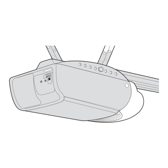
GARAGE DOOR OPENER
Models 2110 1/3 HP
2220 1/2 HP
2220-267 1/2 HP
For Residential Use Only
Owner's Manual
Please read this manual and the enclosed safety materials carefully!
■
Fasten the manual near the garage door after installation.
■
The door WILL NOT CLOSE unless the Protector System
■
properly aligned.
Periodic checks of the opener are required to ensure safe operation.
■
The model number label is located on the front panel of your opener.
■
®
The Chamberlain Group, Inc.
845 Larch Avenue
Elmhurst, Illinois 60126-1196
www.liftmaster.com
is connected and
®
®
Advertisement
Table of Contents

Related Manuals for Chamberlain 2110


Summary of Contents for Chamberlain 2110
- Page 1 The Chamberlain Group, Inc. 845 Larch Avenue Elmhurst, Illinois 60126-1196 www.liftmaster.com ® ® GARAGE DOOR OPENER Models 2110 1/3 HP 2220 1/2 HP 2220-267 1/2 HP For Residential Use Only Owner’s Manual Please read this manual and the enclosed safety materials carefully! ■...
-
Page 2: Table Of Contents
TABLE OF CONTENTS Introduction Adjustment 23-25 Safety symbol and signal word review......2 Adjust the travel limits ..........23 Preparing your garage door ........3 Adjust the force ............24 Tools needed ...............3 Test the safety reversal system.........25 Planning ..............4 Test the Protector System ........25 ®... -
Page 3: Preparing Your Garage Door
Preparing your garage door WARNING Before you begin: To prevent possible SERIOUS INJURY OR DEATH: • Disable locks. • ALWAYS call a trained door systems technician if CAUTION • Remove any ropes connected to garage door. garage door binds, sticks, or is out of balance. An unbalanced garage door may not reverse when •... -
Page 4: Planning
Planning Identify the type and height of your garage door. Survey your garage area to see if any of the conditions below apply to your installation. Additional materials may be required. You may find it helpful to refer back to this page and the accompanying illustrations as you proceed with the installation of your opener. -
Page 5: Carton Inventory
Parts may be stuck in the foam. below. Accessories will depend on the model Hardware for installation is also listed below. Models 2220, 2220-267 Model 2110 Models 2220 (1), 2220-267 (2) Model 2110 (1) 2 Conductor Bell Wire White & White/Red SECURITY✚ SECURITY✚ 1-Button Remote Control... -
Page 6: Assembly
ASSEMBLY STEP 1 HARDWARE SHOWN ACTUAL SIZE Fasten the Rail to the Motor Unit Lock Nut Hex Bolt 1/4" - 20 1/4" - 20 x 5/8" To avoid installation difficulties, do not run the garage door opener until instructed to do so. To aid in assembly and installation, replace the foam packing around the motor unit. -
Page 7: Attach The Rail Brackets
ASSEMBLY STEP 3 Lock Nuts Attach the Rail Brackets 1/4"-20 Rail Brackets • Align rail brackets to end of rail assembly, as shown. • Insert two 1/4"-20 x 5/8" hex bolts and lock nuts. Tighten securely with a 7/16" socket. Hex Bolts You have now finished assembling your garage 1/4"-20x5/8... -
Page 8: Determine The Header Bracket Location
Unfinished INSTALLATION STEP 1 OPTIONAL Ceiling CEILING Determine the Header Bracket MOUNT Location HEADER BRACKET Header Wall WARNING WARNING Vertical Centerline of Garage Door To prevent possible SERIOUS INJURY or DEATH: • Header bracket MUST be RIGIDLY fastened to Structural CAUTION WARNING Supports... -
Page 9: Install The Header Bracket
INSTALLATION STEP 2 Install the Header Bracket Wall Mounting Holes You can attach the header bracket either to the wall above the garage door, or to the ceiling. Follow the CEILING MOUNT ONLY The nail hole is for positioning only. instructions which will work best for your particular You must use lag screws requirements. -
Page 10: Attach The Rail To The Header Bracket
INSTALLATION STEP 3 Attach the Rail to the Header Bracket • Position the opener on the garage floor below the header bracket. Use packing material as a protective base. NOTE: If the door spring is in the way you’ll need help. Have someone hold the opener securely on a temporary support to allow the rail to clear the spring. -
Page 11: Install The Protector System
WARNING INSTALLATION STEP 4 Install The Protector System ® • Be sure power is not connected to the garage door opener BEFORE installing the safety reversing sensor. CAUTION The safety reversing sensor must be connected • To prevent SERIOUS INJURY or DEATH from a closing and aligned correctly before the garage door garage door: opener will move in the down direction. - Page 12 INSTALLING THE BRACKETS Be sure power to the opener is disconnected. Figure 1 DOOR TRACK MOUNT (RIGHT SIDE) Install and align the brackets so the sensors will face each other across the garage door, with the beam no higher than 6" (15 cm) above the floor. They may be Door Track installed in one of three ways, as follows:...
- Page 13 MOUNTING AND WIRING THE SAFETY Figure 5 SENSORS • Slide a 1/4"-20x1/2" carriage bolt head into the Wing Nut slot on each sensor. Use wing nuts to fasten sensors to brackets, with lenses pointing toward each other across the door. Be sure the lens is not Carriage Bolt obstructed by a bracket extension (Figure 5).
-
Page 14: Position The Opener
WARNING CAUTION INSTALLATION STEP 5 Position the Opener To prevent damage to garage door, rest garage door opener rail on 2x4 placed on top section of door. Follow instructions which apply to your door type as illustrated. SECTIONAL DOOR OR ONE-PIECE DOOR WITH TRACK A 2x4 laid flat is convenient for setting an ideal door-to-rail distance. -
Page 15: Hang The Opener
WARNING INSTALLATION STEP 6 Hang the Opener To avoid possible SERIOUS INJURY from a falling garage door opener, fasten it SECURELY to structural CAUTION Three representative installations are shown. Yours supports of the garage. Concrete anchors MUST be used may be different. Hanging brackets should be angled if installing any brackets into masonry. -
Page 16: Install The Door Control
WARNING WARNING INSTALLATION STEP 7 CAUTION WARNING Install the Door Control To prevent possible SERIOUS INJURY or DEATH from electrocution: Locate door control within sight of the door at a minimum • Be sure power is not connected BEFORE installing door height of 5 feet (1.5 m) where small children cannot reach, control. -
Page 17: Install The Lights
WARNING CAUTION INSTALLATION STEP 8 Install the Lights To prevent possible OVERHEATING of the endpanel or light socket, • Install up to a 100 watt maximum light bulb in each • DO NOT use short neck or specialty light bulbs. socket. -
Page 18: Electrical Requirements
WARNING WARNING INSTALLATION STEP 10 Electrical Requirements To prevent possible SERIOUS INJURY or DEATH from electrocution or fire: CAUTION WARNING To avoid installation difficulties, do not run the • Be sure power is not connected to the opener, and opener at this time. disconnect power to circuit BEFORE removing cover to To reduce the risk of electric shock, your garage door establish permanent wiring connection. -
Page 19: Fasten The Door Bracket
WARNING CAUTION INSTALLATION STEP 12 Fasten the Door Bracket To prevent damage to garage door, reinforce inside of door with angle iron both vertically and horizontally. Follow instructions which apply to your door type as illustrated below or on the following page. A horizontal reinforcement brace should be long enough to be secured to two or three vertical Header... - Page 20 ONE-PIECE DOORS Please read and comply with the warnings and reinforcement instructions on the previous page. They apply to one-piece doors also. • Center the door bracket on the top of the door, in line with the header bracket as shown. Mark either the left and right, or the top and bottom holes.
-
Page 21: Connect Door Arm To Trolley
INSTALLATION STEP 13 Inner Outer Connect Door Arm to Trolley Trolley Trolley Follow instructions which apply to your door type as illustrated below and on the following page. SECTIONAL DOORS ONLY Ring Clevis Pin Fastener • Make sure garage door is fully closed. Pull the 5/16"x1"... -
Page 22: Connect The Door Arm To The Trolley
ALL ONE-PIECE DOORS Door Bracket Ring 1. Assemble the door arm, Figure 4: Fastener Nuts • Fasten the straight and curved door arm sections Lock 5/16"-18 Washers together to the longest possible length (with a 2 5/16" or 3 hole overlap). Clevis Pin Straight 5/16"x1-1/4"... -
Page 23: Adjust The Travel Limits
WARNING ADJUSTMENT STEP 1 Adjust the UP and DOWN Travel Without a properly installed safety reversal system, Limits persons (particularly small children) could be CAUTION SERIOUSLY INJURED or KILLED by a closing garage Limit adjustment settings regulate the points at which door. -
Page 24: Adjustment
WARNING ADJUSTMENT STEP 2 Adjust the Force Without a properly installed safety reversal system, persons (particularly small children) could be CAUTION Force adjustment controls are located on the back SERIOUSLY INJURED or KILLED by a closing garage panel of the motor unit. Force adjustment settings door. -
Page 25: Test The Safety Reversal System
WARNING ADJUSTMENT STEP 3 Test the Safety Reversal System Without a properly installed safety reversal system, persons (particularly small children) could be CAUTION SERIOUSLY INJURED or KILLED by a closing garage TEST door. • With the door fully open, place a 1-1/2" (3.8 cm) •... -
Page 26: Operation
WARNING OPERATION IMPORTANT SAFETY INSTRUCTIONS WARNING To reduce the risk of SEVERE INJURY or DEATH: 1. READ AND FOLLOW ALL WARNINGS AND 8. NEVER use handle to pull garage door open or closed. INSTRUCTIONS. If rope knot becomes untied, you could fall. 2. -
Page 27: Using The Wall-Mounted Door Control
Using the Wall-Mounted B) To operate one door using all three buttons on the hand-held remote: Door Control You may program the remote to Press the push button to open or close open the door with the large Open Push the door. -
Page 28: Care Of Your Garage Door Opener
MAINTENANCE SCHEDULE CARE OF YOUR OPENER Once a Month LIMIT AND FORCE ADJUSTMENTS: • Manually operate door. If it is unbalanced or binding, call a trained door systems technician. Weather conditions may cause some minor changes in door • Check to be sure door opens & closes fully. Adjust operation requiring some limits and/or force if necessary. -
Page 29: Having A Problem
HAVING A PROBLEM? 1. My door will not close and the light bulbs blink on my motor unit: The safety reversing sensor must be connected and aligned correctly before the garage door opener will move in the down direction. • Verify the safety sensors are properly installed, aligned and free of any obstructions. -
Page 30: Diagnostic Chart
Installed Diagnostics Safety Sensor Located On Motor Unit LED or Your garage door opener is programmed with Diagnostic self-diagnostic capabilities. The “Learn” button/diagnostic LED will flash a number of times then pause signifying it "Learn" Button has found a potential issue. Consult Diagnostic Chart below. Diagnostic Chart 1 FLASH Symptom: One or both of the Indicator lights on the safety sensors do... -
Page 31: Programming
PROGRAMMING NOTICE: If this Security ✚ ® garage door opener is operated with a non-rolling code transmitter, the technical measure in the receiver of the garage door opener, which provides security against code-theft devices, will be circumvented. The owner of the copyright in the garage door opener does not authorize the purchaser or supplier of the non-rolling code transmitter to circumvent that technical measure. -
Page 32: To Add, Reprogram Or Change A Keyless Entry Pin
To Add, Reprogram or Change a Keyless Entry PIN NOTE: Your new Keyless Entry must be programmed to operate your garage door opener. USING THE “LEARN” BUTTON USING THE MULTI-FUNCTION DOOR CONTROL 1. Press and release the “learn” NOTE: This method requires two people if the Keyless button on motor unit. -
Page 33: Repair Parts
REPAIR PARTS Rail Assembly Parts KEY PART NO. NO. DESCRIPTION 41A4795 Hardware bag (includes sprocket coupling) 12B569-1 Left rail bracket 12B569-2 Right rail bracket 81C168 Rack 41C4677 Complete trolley assembly 1D4828-1 Screw Drive one-piece rail 41A4836 Drive sprocket kit 25C20 Sprocket coupling Installation Parts PART... -
Page 34: Motor Unit Assembly Parts
Low voltage wire harness 41C5416 High voltage wire harness 12A373 Capacitor bracket 41A5389-1D Receiver logic board assy. 41A3150 Terminal block w/screws 41A5490-5 Cover (Model 2110) 41D4671 Limit switch assembly 41A5490-6 (Model 2220) 12D630 Bracket: light socket, limit switch 41C22-1 Drive coupling hub 41A5388 Motor drive assy. -
Page 35: Accessories
Enables homeowner to open television or other appliance from their garage door manually from outside by car with their garage door opener remote disengaging trolley. or from anywhere in their home with an additional LiftMaster Security✚ ® remote. 59LM Outside Keylock: 971LM 1-Button Security✚... -
Page 36: Repair Parts And Service
Model 2220 and 2220-267: The motor is fully warranted for the lifetime of the product to the first-time purchaser. Model 2110: The motor is warranted to be free from any defect in materials and/or workmanship for a period of 24 full months (2 years) from the date of purchase.
Need help?
Do you have a question about the 2110 and is the answer not in the manual?
Questions and answers