Table of Contents
Advertisement
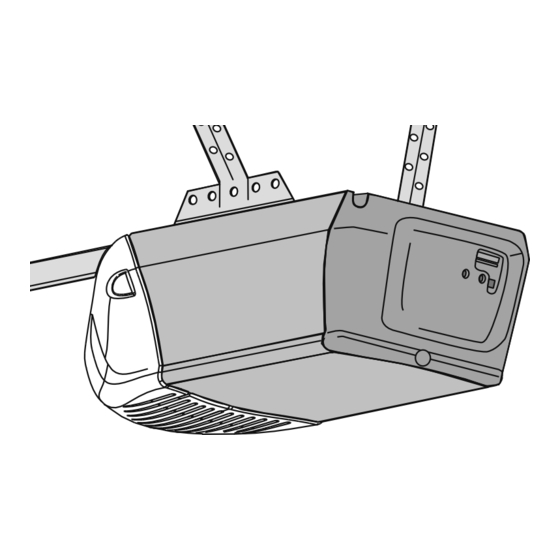
GARAGE DOOR OPENER
Models
3130M 1/3 HP
For Residential Use Only
Owner's Manual
■ Please read this manual and the enclosed safety materials carefully!
■ Fasten the manual near the garage door after installation.
■ The door WILL NOT CLOSE unless the Protector System
■ Periodic checks of the opener are required to ensure safe operation.
■ The model number label is located on the front panel of your opener.
®
®
is connected and properly aligned.
The Chamberlain Group, Inc.
Elmhurst, Illinois 60126-1196
3240M 1/2 HP
845 Larch Avenue
www.liftmaster.com
Advertisement
Table of Contents

Related Manuals for Chamberlain 3240


Summary of Contents for Chamberlain 3240
- Page 1 The Chamberlain Group, Inc. 845 Larch Avenue Elmhurst, Illinois 60126-1196 www.liftmaster.com ® GARAGE DOOR OPENER Models 3130M 1/3 HP 3240M 1/2 HP For Residential Use Only Owner’s Manual ■ Please read this manual and the enclosed safety materials carefully! ■ Fasten the manual near the garage door after installation.
-
Page 2: Table Of Contents
TABLE OF CONTENTS Introduction Adjustment 23-25 Safety symbol and signal word review ....2 Adjust the UP and DOWN travel limits ....23 Preparing your garage door . -
Page 3: Preparing Your Garage Door
Preparing your garage door Before you begin: To prevent possible SERIOUS INJURY or DEATH: • Disable locks. • ALWAYS call a trained door systems technician if • Remove any ropes connected to garage door. garage door binds, sticks, or is out of balance. An •... -
Page 4: Planning
Planning Identify the type and height of your garage door. Survey your garage area to see if any of the conditions below apply to your installation. Additional materials may be required. You may fi nd it helpful to refer back to this page and the accompanying illustrations as you proceed with the installation of your opener. -
Page 5: Carton Inventory
Carton Inventory Your garage door opener is packaged in two cartons If anything is missing, carefully check the packing which contain the motor unit and all parts illustrated material. Parts may be stuck in the foam. Hardware for below. Accessories will depend on the model purchased. installation is also listed below. -
Page 6: Assembly
ASSEMBLY STEP 1 HARDWARE SHOWN ACTUAL SIZE Fasten the Rail to the Motor Unit To avoid installation diffi culties, do not run the garage door opener until instructed to do so. Hex Bolt 1/4"-20x7/16" To aid in assembly and installation, replace the foam packing around the motor unit. -
Page 7: Installation
INSTALLATION IMPORTANT INSTALLATION INSTRUCTIONS WARNING WARNING To reduce the risk of SEVERE INJURY or DEATH: 1. READ AND FOLLOW ALL INSTALLATION 8. NEVER wear watches, rings or loose clothing while WARNINGS AND INSTRUCTIONS. installing or servicing opener. They could be caught in garage door or opener mechanisms. -
Page 8: Determine The Header Bracket Location
INSTALLATION STEP 1 OPTIONAL Unfi nished Ceiling CEILING Determine the Header Bracket Location MOUNT HEADER BRACKET Header Wall Vertical Centerline To prevent possible SERIOUS INJURY or DEATH: of Garage Door • Header bracket MUST be RIGIDLY fastened to Structural structural support on header wall or ceiling, Supports otherwise garage door might NOT reverse when required. -
Page 9: Install The Header Bracket
Wall Mounting Holes INSTALLATION STEP 2 The nail hole is for positioning only. You must Install the Header Bracket use lag screws to mount the header bracket. You can attach the header bracket either to the wall above the garage door, or to the ceiling. Follow the instructions which will work best for your particular requirements. -
Page 10: Attach The Rail To The Header Bracket
INSTALLATION STEP 3 Attach the Rail to the Header Bracket • Position the opener on the garage fl oor below the header bracket. Use packing material as a protective base. NOTE: If the door spring is in the way you’ll need help. -
Page 11: Install The Protector System
INSTALLATION STEP 4 Install The Protector System ® Be sure power is NOT connected to the garage door opener BEFORE installing the safety reversing sensor. The safety reversing sensor must be connected and To prevent SERIOUS INJURY or DEATH from a aligned correctly before the garage door opener will closing garage door: move in the down direction. - Page 12 INSTALLING THE BRACKETS Figure 1 DOOR TRACK MOUNT (RIGHT SIDE) Be sure power to the opener is disconnected. Install and align the brackets so the sensors will face each other Door across the garage door, with the beam no higher than 6" Track (15 cm) above the fl...
- Page 13 MOUNTING AND WIRING THE SAFETY SENSORS Wing Nut • Slide a 1/4"-20x1/2" carriage bolt head into the slot on each sensor. Use wing nuts to fasten sensors to brackets, with lenses pointing toward each other across the door. Be sure the lens is not obstructed by a bracket extension (Figure 5).
-
Page 14: Position The Opener
INSTALLATION STEP 5 Position the Opener To prevent damage to garage door, rest garage door opener rail on 2x4 placed on top section of door. Follow instructions which apply to your door type as illustrated. SECTIONAL DOOR OR ONE-PIECE DOOR WITH TRACK A 2x4 laid fl... -
Page 15: Hang The Opener
INSTALLATION STEP 6 Hang the Opener To avoid possible SERIOUS INJURY from a falling garage door opener, fasten it SECURELY to structural Three representative installations are shown. Yours may supports of the garage. Concrete anchors MUST be be different. Hanging brackets should be angled used if installing ANY brackets into masonry. -
Page 16: Install The Door Control
INSTALLATION STEP 7 Install the Door Control To prevent possible SERIOUS INJURY or DEATH from Locate door control within sight of the door at a minimum electrocution: height of 5 feet (1.5 m) where small children cannot reach, and away from moving parts of the door and door •... -
Page 17: Install The Lights
INSTALLATION STEP 8 Install the Lights To prevent possible OVERHEATING of the endpanel or light socket: • Press the release tabs on both sides of lens. Gently • DO NOT use short neck or specialty light bulbs. rotate lens back and downward until the lens hinge is •... -
Page 18: Electrical Requirements
INSTALLATION STEP 10 Electrical Requirements To prevent possible SERIOUS INJURY or DEATH from electrocution or fi re: To avoid installation diffi culties, do not run the opener at this time. • Be sure power is NOT connected to the opener, and disconnect power to circuit BEFORE removing cover To reduce the risk of electric shock, your garage door to establish permanent wiring connection. -
Page 19: Fasten The Door Bracket
INSTALLATION STEP 12 Fasten the Door Bracket Fiberglass, aluminum or lightweight steel garage doors WILL REQUIRE reinforcement BEFORE installation Follow instructions which apply to your door type of door bracket. Contact your door manufacturer for as illustrated below or on the following page. reinforcement kit. - Page 20 ONE-PIECE DOORS Please read and comply with the warnings and HARDWARE SHOWN ACTUAL SIZE reinforcement instructions on the previous page. They apply to one-piece doors also. • Center the door bracket on the top of the door, in line with the header bracket as shown. Mark either the left and right, or the top and bottom holes.
- Page 21 Figure 1 Outer Trolley Inner Trolley INSTALLATION STEP 13 Connect Door Arm to Trolley Follow instructions which apply to your door type as illustrated below and on the following page. Ring Clevis Pin SECTIONAL DOORS ONLY Fastener 5/16"x1" • Make sure garage door is fully closed. Pull the emergency release handle to disconnect the outer Straight trolley from the inner trolley.
-
Page 22: Connect The Door Arm To The Trolley
ALL ONE-PIECE DOORS Figure 5 CORRECT INCORRECT 1. Assemble the door arm, Figure 5: IMPORTANT: The groove on the straight door arm MUST Straight face away from the curved door arm (Figure 5). Straight Door Arm Door Arm • Fasten the straight and curved door arm sections Curved Curved together to the longest possible length (with a 2 or 3... -
Page 23: Adjustment
ADJUSTMENT STEP 1 Adjust the UP and DOWN Travel Limits Without a properly installed safety reversal system, persons (particularly small children) could be Limit adjustment settings regulate the points at which the SERIOUSLY INJURED or KILLED by a closing garage door will stop when moving up or down. -
Page 24: Adjust The Force
ADJUSTMENT STEP 2 Adjust the Force Without a properly installed safety reversal system, persons (particularly small children) could be Force adjustment controls are located on the back panel SERIOUSLY INJURED or KILLED by a closing garage of the motor unit. Force adjustment settings regulate the door. -
Page 25: Test The Safety Reversal System
ADJUSTMENT STEP 3 Test the Safety Reversal System Without a properly installed safety reversal system, persons (particularly small children) could be TEST SERIOUSLY INJURED or KILLED by a closing garage door. • With the door fully open, place a 1-1/2" (3.8 cm) board (or a 2x4 laid fl... -
Page 26: Operation
OPERATION IMPORTANT SAFETY INSTRUCTIONS WARNING WARNING To reduce the risk of SEVERE INJURY or DEATH: 1. READ AND FOLLOW ALL WARNINGS If one control (force or travel limits) is adjusted, the AND INSTRUCTIONS. other control may also need adjustment. ALWAYS keep remote controls out of reach of 10. -
Page 27: Using The Wall-Mounted Door Control
Using the Wall-Mounted Door Control To Open the Door Manually Press the push button to open or close the door. Press again to Push reverse the door during the closing Button cycle or to stop the door while it’s To prevent possible SERIOUS INJURY or DEATH from opening. -
Page 28: Care Of Your Garage Door Opener
MAINTENANCE SCHEDULE Care of Your Opener Every Month LIMIT AND FORCE ADJUSTMENTS: • Manually operate door. If it is unbalanced or binding, call FORCE CONTROLS Weather conditions may a trained door systems technician. cause some minor changes • Check to be sure door opens & closes fully. Adjust limits in door operation requiring and/or force if necessary. -
Page 29: Having A Problem
HAVING A PROBLEM? 1. My door will not close and the light bulbs blink on Bell Wire my motor unit: The safety reversing sensor must be connected and aligned correctly before the garage door opener will move in the down direction. •... -
Page 30: Diagnostic Chart
Installed Diagnostics Safety Reversing Located On Sensor Motor Unit Your garage door opener is programmed with LED or self-diagnostic capabilities. The “Learn” button/diagnostic Diagnostic LED will fl ash a number of times then pause signifying LED “Learn” it has found a potential issue. Consult Diagnostic Chart Button below. -
Page 31: Programming
PROGRAMMING NOTICE: If this Security ✚ garage door opener is operated with a non-rolling code transmitter, the technical measure ® in the receiver of the garage door opener, which provides security against code-theft devices, will be circumvented. The owner of the copyright in the garage door opener does not authorize the purchaser or supplier of the non-rolling code transmitter to circumvent that technical measure. -
Page 32: To Add, Reprogram Or Change A Keyless Entry Pin
To Add, Reprogram or Change a Keyless Entry PIN NOTE: Your new Keyless Entry must be programmed to operate your garage door opener. USING THE “LEARN” BUTTON USING THE MULTI-FUNCTION DOOR CONTROL NOTE: This method requires two people if the Keyless 1. -
Page 33: Repair Parts
REPAIR PARTS Rail Assembly Parts KEY PART DESCRIPTION 41A6353 Hardware bag (includes sprocket coupling) 81C275 Rack 41A6262 Complete trolley assembly 3077SD Screw Drive one-piece rail 7' (2.1 m) 3088SD Screw Drive one-piece rail 8' (2.4 m) 41A4836 Drive sprocket kit 25C20 Coupling 41A6312... -
Page 34: Motor Unit Assembly Parts
30B638 Capacitor – 1/3 HP 41AS050R1M Receiver logic board 41A3150 Terminal block w/screws assembly (3130) 41AS050R2M Receiver logic board 41D4671 Limit switch assembly assembly (3240) 41A6241 Motor drive assembly 41A5525-57 Cover (Model 3130) 20B21-1 Drive belt 41A5525-53 (Model 3240) 41C4672... -
Page 35: Accessories
Ideal for homes with up to three in their home with an additional garage doors. Combine up to three LiftMaster Security✚ remote. ® controls into one wall control panel for a neat compact appearance. -
Page 36: Warranty
Service number for a list of dealers in your area. TOLL FREE NUMBER: 1-800-528-9131 LIFTMASTER 1 YEAR LIMITED WARRANTY LIFETIME MOTOR WARRANTY (MODEL 3240M) 2 YEAR LIMITED MOTOR WARRANTY (MODEL 3130M) The Chamberlain Group, Inc. (“Seller”) warrants to the fi rst retail purchaser of this product, for the residence in which this...
Need help?
Do you have a question about the 3240 and is the answer not in the manual?
Questions and answers