Table of Contents
Advertisement
Advertisement
Table of Contents

Subscribe to Our Youtube Channel
Related Manuals for AXIOMTEK NA-320 Series


Summary of Contents for AXIOMTEK NA-320 Series
- Page 1 NA-320 Series Network Appliance User’s Manual...
- Page 2 AXIOMTEK does not warrant or assume any legal liability or responsibility for the accuracy, completeness or usefulness of any information in this document. AXIOMTEK does not make any commitment to update the information in this manual.
-
Page 3: Safety Approvals
Safety Approvals CE Marking FCC Class B(NA-320/NA-320FL) FCC Compliance This equipment has been tested and complies with the limits for a Class B digital device, pursuant to Part 15 of the FCC Rules. These limits are designed to provide reasonable protection against harmful interference in a residential installation. -
Page 4: Safety Precautions
Most electronic components are sensitive to static electrical charge. 2. Disconnect the power cords from the NA-320 Series before making any installation. Be sure both the system and the external devices are turned OFF. Sudden surge of power could ruin sensitive components. -
Page 5: Table Of Contents
Table of Contents Disclaimers................. ii Safety Approvals ............... iii Safety Precautions ............iv CHAPTER 1 ..............1 INTRODUCTION ............1 General Description ........... 1 Features ............2 Specifications ............ 3 1.3.1 System ................ 3 1.3.2 Mechanical / Environmental ........5 Dimensions and Outlines ........ - Page 6 2.5.6 Serial Port1 (For Console) Connector (COM1) ..30 2.5.7 Serial Port2 Connector (COM2) ........ 31 2.5.8 CPU FAN Connector (FAN1) ........31 2.5.9 System FAN Connector (FAN2) ........ 31 2.5.10 PS2 Keyboard/Mouse Connector (KM1) ....32 2.5.11 Serial ATA Connector: SATA1, SATA3 ....32 2.5.12 Compact Flash™...
-
Page 7: Chapter 1
NA-320 Series Network Appliance User’s Manual CHAPTER 1 INTRODUCTION This chapter contains general information and detailed specifications of the NA-320 Series Network Appliance Server. Chapter 1 contains the following sections: General Description Features Specifications Dimensions I/O Outlets General Description The NA-320 is a 1U and desktop and NA-320R is a 1U and rackmount network security hardware platform for VPN, firewall and other ®... -
Page 8: Features
NA-320 Series Network Appliance User’s Manual Features Low power and high performance for network security field ® applications. NA-320 series supports Intel ATOM D510 1.66GHz FSB 533; 512K/1M L2 Cache.(D410 for optional) Supports Six 10/100/1000Mbps Ethernet ports Supports BIOS redirected to COM port features Supports one 2.5”... -
Page 9: Specifications
NA-320 Series Network Appliance User’s Manual Specifications 1.3.1 System System CPU ® Intel D510 1.66GHz FSB 533; 512K/1M L2 Cache processor onboard.(D410 for optional) BIOS AMI 16Mbit PnP Flash BIOS with function of BIOS redirected to COM port System Memory... - Page 10 NA-320 Series Network Appliance User’s Manual Two USB ports in the rear side Console RS-232 Console port is the rear side(RJ-type) Power 1 x 12V, 5A power adapter for NA-320,NA-320FL AC to DC 84W open frame for NA-320R OS Compatibility Redhat 2.6 Kernel...
-
Page 11: Mechanical / Environmental
NA-320 Series Network Appliance User’s Manual 1.3.2 Mechanical / Environmental Form Factor 1U Desktop for NA-320 & NA-320FL 1U Rack mount for NA-320R Power, HDD, Link/Act with transfer rate LAN by pass LED and promgramable LED (NA-320,NA- 320FL for optional) Operation Temperature 0°... - Page 12 NA-320 Series Network Appliance User’s Manual 3.2Kg/4.2Kg (NA-320R) NOTE All specifications and images are subject to change without notice. Introduction...
-
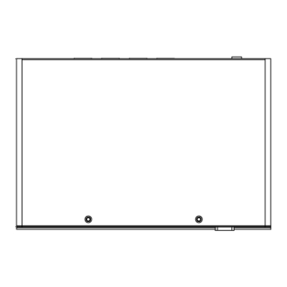
Page 13: Dimensions And Outlines
NA-320 Series Network Appliance User’s Manual Dimensions and Outlines NA-320 Introduction... - Page 14 NA-320 Series Network Appliance User’s Manual NA-320FL NA-320R Introduction...
-
Page 15: I/O Outlets
NA-320 Series Network Appliance User’s Manual 1.5 I/O Outlets Locate the front panel I/O outlets on the NA-320 Series server to connect serial and Ethernet interface devices. 1.5.1 Front Panel for NA-320 &NA-320FL LEDs LEDs LAN By-Pass LED(for optional) While running the LAN By-Pass function, the LED always lights up. - Page 16 NA-320 Series Network Appliance User’s Manual HDD LED The LED flashes when transmitting or receiving any signals. Introduction...
-
Page 17: Rear Panel For Na-320 &Na-320Fl
NA-320 Series Network Appliance User’s Manual 1.5.2 Rear Panel for NA-320 &NA-320FL USB Ports LAN Ports 12V/5A DC Reset/Default Console Power Input Switch Port LAN Ports USB Ports 12V/5A DC Console Power Input Port Console port – RS-232 Console port is for the command of line interface and of diagnostic support by P.O.S.T... - Page 18 NA-320 Series Network Appliance User’s Manual our customer’s OS supports this application. (for optional) Link/Active LED (Single color)for LAN port #1, port#2, port#3, port#4, port#5, port#6 1. The orange LED is on when the LAN port connection is working. 2. The LED flashes when transmitting or receiving any signals to or from the appliance.
-
Page 19: Front Panel For Na-320R
NA-320 Series Network Appliance User’s Manual 1.5.3 Front Panel for NA-320R Power/HDD/ Reset/Default LAN Ports USB Ports Console LAN Bypass Switch Port /GPIO LED Power on LED System and power on HDD LED Link/Active LED (single color) The green LED is on when it is a normal HD connection. - Page 20 NA-320 Series Network Appliance User’s Manual Transmitted LED for LAN port #1, port#2, port#3, port#4, port#5 and port#6 1. The double-color LED light indicates 10/100/1000Mbps transfer rate. `Transfer Rate LED Light Color 10Mbps Dark 100Mbps Green 1000Mbps Amber 2. When the amber-color LED light is radiating, it should be 1000Mbps transfer rate at this moment.
-
Page 21: Rear Panel For Na-320R
NA-320 Series Network Appliance User’s Manual 1.5.4 Rear Panel for NA-320R System Fan AC I nlet System Fan Introduction... - Page 22 NA-320 Series Network Appliance User’s Manual MEMO Introduction...
-
Page 23: Chapter 2
NA-320 Series Network Appliance User’s Manual CHAPTER 2 HARDWARE DESCRIPTION The NA-320 Series are convenient for your various hardware configurations. The chapter 2 will help you get familiar with the hardware. Checklist The package bundled with your NA-320 Series should contain the... -
Page 24: Memory Module (Sodimm)
NA-320 Series Network Appliance User’s Manual Memory Module (SODIMM) The main board supports one DDR2 667 SODIMM socket. Maximum memory capacity is up to 2GB None-ECC unbuffer memory. The following steps show you how to install the memory modules: Push down each side of the SODIMM socket. -
Page 25: Board Layout
NA-320 Series Network Appliance User’s Manual Board Layout Component Side Hardware Description... - Page 26 NA-320 Series Network Appliance User’s Manual Solder Side Hardware Description...
-
Page 27: Jumper Settings
Jumper Settings This section provides the information about jumpers and connectors of NA-320 Series. Proper jumper settings configure the main board in this appliance to meet your application purpose. We are herewith listing a summary table of all jumpers and default settings for onboard devices, respectively. -
Page 28: Switch Button Selection Jumper (Jp1 )
NA-320 Series Network Appliance User’s Manual 2.4.1 Switch Button Selection Jumper (JP1 ) Use this jumper to select the Switch Button Function. Description Function Jumper Setting Switch (SW 2) Power On/Off Button Selection Reset (Default) GPIO Hardware Description... -
Page 29: Lan Bypass Trigger Selection Jumper (Jp2, Jp3)
NA-320 Series Network Appliance User’s Manual 2.4.2 LAN Bypass Trigger Selection Jumper (JP2, JP3) Description Function Jumper Setting LAN Bypass Not install Trigger 1,2 Selection Low Level GPIO (By Pass Enable) High Level GPIO(Default) (By Pass Disable) NOTE If the jumper setting is “Low Level GPIO”, LAN Bypass function will still be started even when power supply is normally input. -
Page 30: Lan Bypass Selection Jumper (Jp4)
NA-320 Series Network Appliance User’s Manual 2.4.3 LAN ByPass Selection Jumper (JP4) Use this jumper to select the LAN Bypass Function. Description Function Jumper Setting LAN By-Pass Disabled Function Always By-Pass Trigger By JP2 ; JP3 or W DT (Default) 2.4.4 CompactFlash... -
Page 31: Clear Cmos Jumper (Jp6)
NA-320 Series Network Appliance User’s Manual 2.4.5 Clear CMOS Jumper (JP6) You may need to use this jumper is to clear the CMOS memory if incorrect settings in the Setup Utility. Description Function Jumper Setting CMOS Clear Normal (Default) Clear CMOS 2.4.6... -
Page 32: Connectors
NA-320 Series Network Appliance User’s Manual Connectors Connectors connect the board with other parts of the system. Loose or improper connection might cause problems. Make sure all connectors are properly and firmly connected. Here is a summary table shows you all connectors on the main board. -
Page 33: Dc-In Power Jack (Cn1) For Na-320 & Na-320Fl
NA-320 Series Network Appliance User’s Manual 2.5.1 DC-In Power Jack (CN1) for NA-320 & NA-320FL Signal 2.5.2 Power out Connector (CN2) Signal +12V Hardware Description... -
Page 34: Lcm Or Sata Power Connector (Cn7)
NA-320 Series Network Appliance User’s Manual 2.5.3 LCM or SATA Power Connector (CN7) Support 2.5” SATA HDD power or LCM module Signal RXD of COM2 No Connection TXD of COM2 2.5.4 Mini Card Connector (CN8) Signal Signal PCIE_WAKE- +3.3V +1.5 V... -
Page 35: Front Panel Bezel Connector (Cn9)
NA-320 Series Network Appliance User’s Manual SMB_CLK SMB_DATA USB_D- USB_D+ +1.5V +3.3V 2.5.5 Front Panel Bezel Connector (CN9) 1. Power LED: : : : This 3-pin connector (Pin 1, 3, 5) connects a LED indicator to the system power switch on the case. Pin 1 is assigned as +, and Pin 3, Pin 5 as -. -
Page 36: Serial Port1 (For Console) Connector (Com1)
NA-320 Series Network Appliance User’s Manual connecting the CPU card to an internal buzzer, please short pins 2-4; while connecting to an external speaker, you need to set pins 2-4 to Open and connect the speaker cable to pin 8 (+) and pin 2 (-). -
Page 37: Serial Port2 Connector (Com2)
NA-320 Series Network Appliance User’s Manual 2.5.7 Serial Port2 Connector (COM2) Signal Data Carrier Detect (DCD) Data Set Ready(DSR) Receive Date(RXD) Request to Send(RTS) Transmit Data(TXD) Clear to Send(CTS) Data Terminal Ready Ring Indicator(RI) 2.5.8 CPU FAN Connector (FAN1) Signal... -
Page 38: Ps2 Keyboard/Mouse Connector (Km1)
NA-320 Series Network Appliance User’s Manual 2.5.10 PS2 Keyboard/Mouse Connector (KM1) The board supports a keyboard and Mouse interface. Connector CN14 is for PS/2 keyboard Connection VIA “Y” Cable. Signal Signal K/B Data K/B CLK M/S Data M/S CLK 2.5.11 Serial ATA Connector: SATA1, SATA3 The SATA connector is for high-speed SATA interface port and it can be connected to hard disk device. -
Page 39: Compact Flash™ Socket:scf1
NA-320 Series Network Appliance User’s Manual SATA1 SATA3 2.5.12 Compact Flash™ Socket: : : : SCF1 Signal Signal Data 3 Data 4 Data 5 Data 6 Data 7 CS0# Address 10 ATASEL Address 9 Address 8 Address 7 Address 6... -
Page 40: Usb Port0~Port1 Connector (Usb1)
NA-320 Series Network Appliance User’s Manual VS1# IORD# IOWR# INTR CSEL# VS2# RESET# IORDY# DMAREQ DMAACK- DASP# PDIAG# Data 8 Data 9 Data 10 2.5.13 USB Port0~Port1 Connector (USB1) Signal USB_POWER USB_PN0 USB_PP0 USB_POWER USB_PN1 USB_PP1 Hardware Description... -
Page 41: Vga Connector (Vga1)
NA-320 Series Network Appliance User’s Manual 2.5.14 VGA Connector (VGA1) Signal Signal DETECT GREEN BLUE DDC DATA Horizontal Sync Vertical Sync DDC CLK 2.5.15 LED1~LED8 Signal LED1 For Lan1 Up : LINK (Green : LINK100 ; Amber : LINK1000) Down : Active (Orange) -
Page 42: Usb Port2~Port3 Connector (Usb2)
NA-320 Series Network Appliance User’s Manual LED6 For Lan6 Up : LINK (Green : LINK100 ; Amber : LINK1000) Down : Active (Orange) LED7 Up : Power LED (Green) Down : GPIO (Programmable LED; Option) LED8 Up : HDD LED (Green) Down : Lan Bypass LED (Option) 2.5.16 USB Port2~Port3 Connector (USB2) -
Page 43: Chapter 3
NA-320 Series Network Appliance User’s Manual CHAPTER 3 AMI BIOS SETUP UTILITY This chapter provides users with detailed description how to set up basic system configuration through the AMIBIOS8 BIOS setup utility. 3.1 Starting To enter the setup screens, follow the steps below: Turn on the computer and press the <Del>... -
Page 44: Main Menu
NA-320 Series Network Appliance User’s Manual The <F10> key allows you to save any changes you have made and exit Setup. Press the <F10> key to save your changes. The <Esc> key allows you to discard any changes you have made and exit the Setup. Press the <Esc>... -
Page 45: Advanced Menu
NA-320 Series Network Appliance User’s Manual System Time/Date Use this option to change the system time and date. Highlight System Time or System Date using the <Arrow> keys. Enter new values through the keyboard. Press the <Tab> key or the <Arrow>... - Page 46 NA-320 Series Network Appliance User’s Manual CPU Configuration This screen shows the CPU Configuration, and you can change the value of the selected option. IDE Configuration You can use this screen to select options for the IDE Configuration, and change the value of the selected option. A description of the selected item appears on the right side of the screen.
- Page 47 NA-320 Series Network Appliance User’s Manual ATA/IDE Configuration Use this item to specify the integrated IDE controller. There are three options for your selection: Disable, Compatible and Enhanced. Legacy IDE Channels When the ATA/IDE Configuration is set to Compatible, this item will be displayed.
- Page 48 NA-320 Series Network Appliance User’s Manual Serial Port1 Address This option specifies the base I/O port address and Default setting is 3F8. Here are the options for your selection, Disabled. Serial Port2 Address This option specifies the base I/O port address and Default setting is 2F8.
- Page 49 NA-320 Series Network Appliance User’s Manual System Temperature Show you the current system temperature. CPU Temperature These read-only fields show the functions of the hardware thermal sensor by CPU thermal diode that monitors the chip blocks to ensure a stable system.
- Page 50 NA-320 Series Network Appliance User’s Manual AMI BIOS Setup Utility...
- Page 51 NA-320 Series Network Appliance User’s Manual General ACPI Configuration Scroll to this item and press <Enter> to view the General ACPI Configuration sub menu, which contains General ACPI (Advanced Configuration and Power Management Interface) options for your configuration. Suspend mode After the selected period of system inactivity (1 minute to 1 hour), all devices except the CPU shut off.
- Page 52 NA-320 Series Network Appliance User’s Manual Advanced ACPI Configuration Scroll to this item and press <Enter> to view the Advanced ACPI Configuration sub menu, which contains Advanced ACPI (Advanced Configuration and Power Management Interface) options for your configuration. ACPI Version Features This item shows ACPI’s version.
- Page 53 NA-320 Series Network Appliance User’s Manual Serial port number This item specifies the base I/O port address and Interrupt Request address of serial port 1. The Optimal setting is 3F8/IRQ4. Serial Port Mode This item allows you to setup the data transfer rate for the console port.
- Page 54 NA-320 Series Network Appliance User’s Manual Configuration options: ANSI, VT100 and VT-UTF8. VT-UTF8 Combo Key Support Use this item to “Enabled” or “Disabled” VT-UTF8 combination key supports for ANSI / VT100 therminals. Sredir Memory Display Delay This item allows you to indicate the length of time in seconds to off the memory display delay.
-
Page 55: Boot Menu
NA-320 Series Network Appliance User’s Manual Boot Menu The Boot menu allows users to change boot options of the system. You can select any of the items in the left frame of the screen to go to the sub menus: For items marked with “... - Page 56 NA-320 Series Network Appliance User’s Manual Quick Boot Enabling this item lets the BIOS skip some power on self tests (POST). The default setting is Enabled. AddOn ROM Display Mode This item selects the display mode for option ROM. The default setting is Force BIOS.
- Page 57 NA-320 Series Network Appliance User’s Manual pressed when error occurs. The default setting is Enabled. Hit ‘DEL’ Message Display If this item is enabled, the system displays the message “Press DEL to run Setup” during POST. The default setting is Enabled.
-
Page 58: Security Menu
NA-320 Series Network Appliance User’s Manual 3.6 Security Menu The Security menu allows users to change the security settings for the system. Supervisor Password This item indicates whether a supervisor password has been set. If the password has been installed, Installed displays. -
Page 59: Chipset Menu
NA-320 Series Network Appliance User’s Manual Chipset Menu The Chipset menu allows users to change the advanced chipset settings. You can select any of the items in the left frame of the screen to go to the sub menus: North Bridge Configuration South Bridge Configuration For items marked with “... - Page 60 NA-320 Series Network Appliance User’s Manual Video Function Configuration This item is for setting up the video function. AMI BIOS Setup Utility...
- Page 61 NA-320 Series Network Appliance User’s Manual DVMT Mode Select DVMT (Dynamic Video Memory Technology) helps you select the video mode. South Bridge Configuration AMI BIOS Setup Utility...
- Page 62 NA-320 Series Network Appliance User’s Manual WDTO Trigger The selections for this item are “HW Reset” / “LAN by pass”. If the system hardware has LAN by pass specification, this item could be choosed to enable for LAN by pass control.
-
Page 63: Exit Menu
NA-320 Series Network Appliance User’s Manual Exit Menu The Exit menu allows users to load your system configuration with optimal or failsafe default values. Save Changes and Exit When you have completed the system configuration changes, select this option to leave Setup and reboot the computer so the new system configuration parameters can take effect. - Page 64 NA-320 Series Network Appliance User’s Manual Discard Changes Use this item to abandon all changes. Load Optimal Defaults It automatically sets all Setup options to a complete set of default settings when you select this option. The Optimal settings are designed for maximum system performance, but may not work best for all computer applications.
-
Page 65: Appendix A
APPENDIX A ENABLING LAN BYPASS FEATURE What is the LAN by-pass meant for NA-320 Series? It doesn’t have any down time in network connections for two other network segments (LAN1 and LAN2) when any fetal errors occur to this device. -
Page 66: Appendix B
NA-320 Series Network Appliance User’s Manual APPENDIX B WARNING This is a class B Product. In a domestic Environment this Product may cause radio interference in which case the user may be required to take adequate measures. It will be danger if battery is incorrectly replaced. Replacing... - Page 67 NA-320 Series Network Appliance User’s Manual “Lay this equipment on a reliable surface when install. A drop or fall could cause injury.” “The equipment shall be installed according to specification as nameplate. Make sure the voltage of the power source when connect the equipment to the power outlet.
Need help?
Do you have a question about the NA-320 Series and is the answer not in the manual?
Questions and answers