Table of Contents
Advertisement
Quick Links
Advertisement
Table of Contents

Related Manuals for AXIOMTEK NA-401


Summary of Contents for AXIOMTEK NA-401
- Page 1 NA-401 Hardware Installation Guide For service person only...
- Page 2 AXIOMTEK assumes no responsibility for any inaccuracies that may be contained in this document. AXIOMTEK makes no commitment to update or to keep current the information contained in this manual.
- Page 3 Safety Approvals CE Marking FCC Class A FCC Compliance This equipment has been tested and complies with the limits for a Class A digital device, pursuant to Part 15 of the FCC Rules. These limits are designed to provide reasonable protection against harmful interference in a residential installation.
- Page 4 Most electronic components are sensitive to static electrical charge. 2. Disconnect the power cords from the NA-401 before making any installation. Be sure both the system and the external devices are turned OFF. Sudden surge of power could ruin sensitive components.
-
Page 5: Table Of Contents
Table of Contents Chapter 1 Introduciton ------------------------------1 General Description .......... 1 Standard Features ..........2 System Specifications ........2 1.3.1 Hardware ..............2 Dimensions ............5 Front Panel Outlets ........... 6 Rear Panel Outlets ..........7 Indications of Front Panel......... 8 Chapter 2 Installation Procedures------------- 11 Preinstallation Checklist ......... - Page 6 3.13 Quit Without Saving ........60 Appendix A Warning ----------------------------- 62...
-
Page 7: General Description
With its innovative mechanical and electrical design, the NA-401 server provides one PCI expansion slot for VPN encryption / decryption adapter board and another special functions enabling. It cans Introduction... -
Page 8: Standard Features
NA-401 Hardware Installation Guide enhancement network security process performance and of-load the CPU loading. The NA-401 can support wonderful networking application platform by excellent cost with performance ratio. Standard Features U-height rack-mount/stacked-up design High performance Intel Pentium 4 processor (LGA775-Pin) Four gigabit LAN ports (through PCI-Express by one interface) combinations are for NA-401. - Page 9 NA-401 Hardware Installation Guide 4 x 10/100/1000 Base-T Ethernet LAN port w/LED through PCI-E by one interface 1 x Console port 2 x USB port Front Panel LED: 1 x LED for HDDs 1 x Power LED for System Processor: ®...
- Page 10 NA-401 Hardware Installation Guide Air temperature: 0° C – 40°C Humidity: 10% – 95% Storage environment: Air temperature: -20° C – 70°C Humidity: 10% – 95% Introduction...
-
Page 11: Dimensions
NA-401 Hardware Installation Guide Dimensions Unit: mm Introduction... -
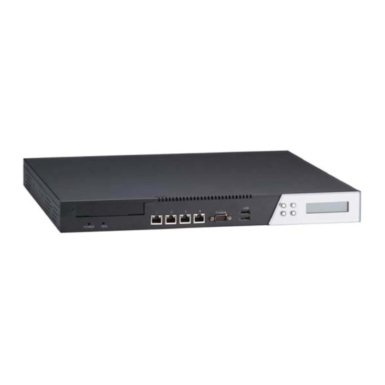
Page 12: Front Panel Outlets
NA-401 Hardware Installation Guide Front Panel Outlets Located at the front panel of the NA-401 server are the I/O outlets for connections of serial and Ethernet interface-supported devices. You also can find out the LCD module. The NA-401 Server Rear Panel... -
Page 13: Rear Panel Outlets
NA-401 Hardware Installation Guide Rear Panel Outlets Located at the rear panel of the NA-401 server are the I/O outlets. You will also find the main power switch and cooling fans. Power Switch 100-240VAC Internal FANs 50-60Hz Power input Introduction... -
Page 14: Indications Of Front Panel
NA-401 Hardware Installation Guide Indications of Front Panel Power on LED 1. System and power on HDD LED Link/Active LED (single color) 1. The green LED is on when the HD has connection normally 2. The LED flashes when there is transmit or receive activity... - Page 15 NA-401 Hardware Installation Guide 3. The LED is dark if the Link/Active LED is light or flash in the same time; it’s on 10Mbps transfer rate 4. The LED is dark if the Link/Active LED is dark also. There is no any networking device was attached.
- Page 16 NA-401 Hardware Installation Guide This page does not contain any information. Introduction...
-
Page 17: Preinstallation Checklist
Quick installation guide Hardware Installation Guide NA-401 cable kits (1 x 44-pin IDE, 1 x console cable, 1 x S-ATA cable, 1 x PS/2 keyboard and mouse cable, 1 x VGA cable) Mounting brackets for rack installation (left/right) x 2 Plastic stand for stack–up x 4... -
Page 18: 2.2 Setting Up The Appliance
This section provides the information about the initial installation to setup the NA-401 2.2.1 Removing and Replacing the Top Cover To gain access into the internal components of the NA-401, you must follow the instructions given below to remove the top cover. Figure 2.1 Installation Procedures... -
Page 19: Installing A Microprocessor (Cpu) 錯 誤 ! 尚 未 定 義 書
NA-401 Hardware Installation Guide Main Board 2.2.2 Installing a Microprocessor (CPU) The Pentium 4 Processor in the 775-land package refers to Pentium 4 processors in the 775-land Flip-Chip Land Grid Array (FC-LGA4) package with an Integrated Heat Spreader (IHS) that aids in heat dissipation to a properly attached fan heat sink. - Page 20 NA-401 Hardware Installation Guide Figure 2.5, Opening the Socket Figure 2.6, Don’t Touch Processor Contacts Figure 2.7, Locate Connection 1 indicator and the two orientation key notches Installation Procedures...
- Page 21 NA-401 Hardware Installation Guide Figure 2.8; Grasp the processor with thumb and index finger. Figure 2.9; Carefully place the package into the socket body using a purely vertical motion. Installation Procedures...
- Page 22 NA-401 Hardware Installation Guide Figure 2.9 Close the socket by 1. Close the Load Plate 2. While pressing down lightly on Load Plate, engage the Load Lever. 3. Secure Load Lever with Load Plate tab under retention tab of Load...
-
Page 23: Installing A Memory Module (Dimm)
NA-401 Hardware Installation Guide Figure 2.10; Put the copper heat sink on the upper of CPU. The fin of heat sink should be vertical run from I/O shield. To use the four screws to clamp the heat sink. Figure 2.11, Then to use the FAN dock to cover the heat sink with CPU. -
Page 24: Installing A Dma/66/100 Hard Drive
To accommodate the fast transfer rate of Ultra DMA/66/100, a cable (with 40 pin connectors on both ends) is necessary when installing Ultra DMA/66/100 drives. The NA-401, on this aspect, can support IDE hard drive and DOM (Disk on Module) deployment. It is through... -
Page 25: Install A Riser Card
NA-401 Hardware Installation Guide Figure 2.12: Put the HDD into a tray. Plug the IDE round cable for hard drive and main board both side. Then put the tray to the right-back site of the system placement. Customer can fix it in the base of chassis by other screws. - Page 26 NA-401 Hardware Installation Guide a small bracket in the front. Then the IO connector can be exposed. 2.2.6 Connectors & Jumpers The connectors allow the CPU card to connect with other parts of the system. Some problems encountered by your system may be a result from loose or improper connections.
- Page 27 NA-401 Hardware Installation Guide Connectors Label Connectors Label General Output Connector CN24 IDE Connector CN23 Printer Port Connector CN21 FDD Connector CN37 COM1 IrDA Connector CN17 COM2 CN29 Mini-PCI Connector CN13 USB Port 1, 2 Connector CN25 S-ATA Port 1 Connector...
- Page 28 NA-401 Hardware Installation Guide Connectors Label Connectors Label Ethernet 2 External Ethernet 2 External Speed LED Link/ACT LED Ethernet 3 External Ethernet 3 External Speed LED Link/ACT LED Ethernet 4 External Ethernet 4 External Speed LED Link/ACT LED Jumper Setting...
-
Page 29: Install Display Interface
Data Carrier Delect(DCD) Data Set Ready(DSR) Receive Date(RXD) Request to Send(RTS) Transmit Data(TXD) Clear to Send(CTS) Data Terminal Ready (DTR) Ring Indicator(RI) 2.2.9 Installing Keyboard and PS/2 Mouse Connectors The NA-401 provides External keyboard (CN9) and Mouse (CN10) Installation Procedures... -
Page 30: Installing Usb Connector
NA-401 Hardware Installation Guide interface with two 5-pin connectors for porting software easily by customer. CN9/CN10 2.2.10 Installing USB Connector (Optional) The Universal Serial Bus (USB) connector (CN6) on the main board is for installation of peripherals supporting the USB interface. - Page 31 NA-401 Hardware Installation Guide Communicate with PC through console cable a) Baud Rate = 9600 b) Data Bits = 8 c) Stop Bits = 2 d) Parity Check = None In fact, the COM Port is only use two signal as Tx and & Rx in data transaction The LCD module model name was called AX89063.
- Page 32 NA-401 Hardware Installation Guide use baud rate as 9600. So the time interval should be 0.5msec for next commands initialization 。 B) data:PC AX89063 The showing data total length should be 80 Bytes of LCM, supposedly.。But, it is only can display 1 to 16 words and 41 to 56 words。...
- Page 33 NA-401 Hardware Installation Guide the LCM. But it will be stored in the RAM of LCM。 C) Keypad data:AX89063 a) ▲ ( Up ):when it was press then release, the LCM will send 55hex to PC,It is ASCII code for ’U’。...
- Page 34 NA-401 Hardware Installation Guide Installation Procedures...
-
Page 35: Chapter 3 Award Bios Utility
NA-401 Hardware Installation Guide Chapter 3 Award BIOS Utility Chapter 3 describes the different settings available in the Award BIOS that comes with the SBC86804. Also contained here are instructions on how to set up the BIOS configuration. BIOS Introduction The Award BIOS (Basic Input/Output System) installed in your computer system’s ROM supports Intel Celeron processors in a... - Page 36 NA-401 Hardware Installation Guide also restart by turning the system OFF and back ON again. The following message will appear on the screen: Press <DEL> to Enter Setup In general, you press the arrow keys to highlight items, <Enter> to select, the <PgUp>...
-
Page 37: Standard Cmos Setup
NA-401 Hardware Installation Guide the Main Menu, just below the control keys section, displays information on the currently highlighted item in the list. NOTE: If you find that your computer cannot boot after making and saving system changes with Setup, the Award BIOS, via its built-in override feature, resets your system to the CMOS default settings. - Page 38 NA-401 Hardware Installation Guide At the bottom of the menu are the control keys for use on this menu. If you need any help in each item field, you can press the <F1> key. It will display the relevant information to help you. The memory display at the lower right-hand side of the menu is read-only.
- Page 39 NA-401 Hardware Installation Guide The day of week, from Sun to Sat, determined by the BIOS, is read only The date, from 1 to 31 (or the maximum allowed in the date month), can key in the numerical / function key The month, Jan through Dec.
- Page 40 NA-401 Hardware Installation Guide information should be provided in the documentation from your hard disk vendor or the system manufacturer. If the controller of HDD interface is ESDI, select “Type 1”. If the controller of HDD interface is SCSI, select “None”.
-
Page 41: Advanced Bios Features
NA-401 Hardware Installation Guide Advanced BIOS Features This section allows you to configure and improve your system and allows you to set up some system features according to your preference. Award BIOS Utility... - Page 42 NA-401 Hardware Installation Guide Delay Prior to Thermal The default is set at 16 minutes, which means the board will wait 16 minutes before it activates the processor's integrated thermal control circuit. You'll undoubtedly want protection against automatic shutdown sooner, so change the 16-minute setting to either four or eight minutes.
- Page 43 NA-401 Hardware Installation Guide Disabled: To turn off the feature Virtualization Technology Enabled: To the make the “CPU Hyper-threading technology” function enabling, that is suitable for multi-tasking operating system Disabled: To turn off the feature Hard Disk Boot Priority This Field will list all of Bootable device such as...
- Page 44 NA-401 Hardware Installation Guide Enabled Enable Quick POST Disabled Normal POST First/Second/Third Boot Device These items allow the selection of the 1 , and 3 devices that the system will search for during its boot-up sequence. The wide range of selection includes Floppy, LS120, ZIP100, Hard Disk, SCSI, and CDROM.
- Page 45 NA-401 Hardware Installation Guide DRAM used is larger the 64MB, you have to select “OS 2”, otherwise (under non-OS2), default is NON-OS2. The default value is “Non-OS2”. Console Redirection This item allows you to enable or disable the BIOS boot up and redirect to console port feature.
-
Page 46: Advanced Chipset Features
NA-401 Hardware Installation Guide Report error message if no floppy disk in win 95 PS/2 mouse function control The IRQ 12 can be reserved to PS/2 mouse. Otherwise, the IRQ 12 will be released to another third-party adapter. The default is enabled. - Page 47 NA-401 Hardware Installation Guide CAS Latency Time CAS Latency is the delay, in clock cycles, between when the READ command is issued and when the data on the DQ pins is valid. Standard values for DDR memory are 2 and 2.5 clock cycles.
- Page 48 NA-401 Hardware Installation Guide tRAS is measured in clock cycled, and is generally somewhere from 5 to 10 clock cycles. Memory Hole at 15M-16M: (Reserved segment of memory for memory.) Some of expansion adapter card will allocate some segment of memory in operating.
-
Page 49: Integrated Peripherals
NA-401 Hardware Installation Guide Integrated Peripherals This option sets your hard disk configuration, mode and port. Award BIOS Utility... - Page 50 NA-401 Hardware Installation Guide Award BIOS Utility...
- Page 51 NA-401 Hardware Installation Guide IDE HDD Block Mode The IDE controller can use the faster multiple section read / write mode to control the equipment. The default is enabled. On-Chip Primary/Secondary PCI IDE The integrated peripheral controller contains an IDE interface with support for two IDE channels.
- Page 52 NA-401 Hardware Installation Guide mode, SATA only. Serial ATA Port0 Mode Primary Master: Remap stat port 0 to IDE Pri. master Primary slave: Remap stat port 0 to IDE Pri. slave Secondary Master: Remap stat port 0 to IDE sec. master Secondary slave: Remap stat port 0 to IDE sec.
-
Page 53: Power Management Setup
NA-401 Hardware Installation Guide Select Enabled if your system contains a Universal Serial Bus (USB) controller and you have a USB keyboard. The choice: Enabled, Disabled. USB Mouse Support Select Enabled if your system contains a Universal Serial Bus (USB) controller and you have a USB Mouse. - Page 54 NA-401 Hardware Installation Guide ACPI Function This item allows you to enable/disable the Advanced Configuration and Power Management (ACPI). The choice: Enabled, Disabled. Power Management Award BIOS Utility...
- Page 55 NA-401 Hardware Installation Guide This item allows you to select the Power Management mode. The choice: User Define, Min Saving, Max Saving. Video off Method In suspending, this item allows you to select the CRT closed method under APM mode.
-
Page 56: Pnp/Pci Configuration
NA-401 Hardware Installation Guide HDD Power Down When enabled and after the set time of system inactivity, the hard disk drive will be powered down while all other devices remain active. The choice: Enabled, Disabled. Resume by Alarm When Enabled, your can set the date and time at which the RTC (real-time clock) alarm awakens the system from Suspend mode. - Page 57 NA-401 Hardware Installation Guide settings. Reset Configuration Data Normally, you leave this field Disabled. Select Enabled to reset Extended System Configuration Data (ESCD) when you exit Setup or if you have installed a new add-on and the system reconfiguration has caused such a serious conflict that the operating system can not boot.
- Page 58 NA-401 Hardware Installation Guide IRQ Resources When resources are controlled manually, assign each system interrupt a type, depending on the type of device using the interrupt. PCI/VGA Palette Snoop Leave this field at Disabled. The choice: Enabled, Disabled. Award BIOS Utility...
-
Page 59: Pc Health Status
NA-401 Hardware Installation Guide PC Health Status This option configures the PCI bus system. All PCI bus systems on the system use INT#, thus all installed PCI cards must be set to this value. Current System Temp. Show you the current system temperature. -
Page 60: Load Optimized Defaults
NA-401 Hardware Installation Guide 3.10 Load Optimized Defaults This option allows you to load the default values to your system configuration. These default settings are optimal and enable all high performance features. To load SETUP defaults value to CMOS SRAM, enter “Y”. If not, enter “N”. -
Page 61: Set Supervisor/User Password
NA-401 Hardware Installation Guide 3.11 Set Supervisor/User Password You can set either supervisor or user password, or both of then. The differences between are: Award BIOS Utility... - Page 62 NA-401 Hardware Installation Guide supervisor password: can enter and change the options of the setup menus. user password: just can enter but do not have the right to change the options of the setup menus. When you select this function, the following message will appear at the center of the screen to assist you in creating a password.
- Page 63 NA-401 Hardware Installation Guide Once the password is disabled, the system will boot and you can enter Setup freely. PASSWORD DISABLED. When a password is enabled, you have to type it every time you enter Setup. This prevents any unauthorized person from changing your system configuration.
-
Page 64: Save & Exit Setup
NA-401 Hardware Installation Guide 3.12 Save & Exit Setup This allows you to determine whether or not to accept the modifications. Typing “Y” quits the setup utility and saves all changes into the CMOS memory. Typing “N” brigs you back to Setup utility. - Page 65 NA-401 Hardware Installation Guide 3.13 Quit Without Saving Select this option to exit the Setup utility without saving the changes you have made in this session. Typing “Y” will quit the Setup utility without saving the modifications. Typing “N” will return you to Setup utility.
- Page 66 NA-401 Hardware Installation Guide This page does not contain any information. Award BIOS Utility...
- Page 67 NA-401 Hardware Installation Guide Appendix A Warning This is a class A Product. In a domestic Environment this Product may cause radio interference in which case the user may be required to take adequate measures. It will be danger if battery is incorrectly replaced. Replacing only with the same or equivalent type is highly recommended by the manufacturer.
- Page 68 格式化: 靠左, 框線:下: (實 心單線, 自動, 0.5 pt 線段粗 NA-401 Hardware Installation Guide 細) “Lay this equipment on a reliable surface when install. A drop or fall could cause injury.” “The equipment shall be installed according to specification as nameplate. Make sure the voltage of the power source when connect the equipment to the power outlet.
Need help?
Do you have a question about the NA-401 and is the answer not in the manual?
Questions and answers