Table of Contents
Advertisement
Quick Links
Advertisement
Table of Contents

Subscribe to Our Youtube Channel
Related Manuals for TC Electronic FireworX


Summary of Contents for TC Electronic FireworX
- Page 1 USERS MANUAL FireworX STUDIO EFFECTS PROCESSOR...
-
Page 3: Table Of Contents
TABLE OF CONTENTS Matrix page, ... . .p. 30 INTRODUCTION PAGE Link page, ....p. 32 Dials page, ....p. 32 Table of contents, . -
Page 4: Introduction
On the other hand, you might want to know a little more about the FireworX before you start pressing keys. The manual will take you through all of the FireworX functions step by step. If you want to read about a specific function, please refer to the... -
Page 5: Features
FireworX uses a dynamic processing power allocation structure. This means that you always get the advantage of the full power of the FireworX, in other words, you can keep adding algorithms to the signal chain until all the processing power of the FireworX is used. -
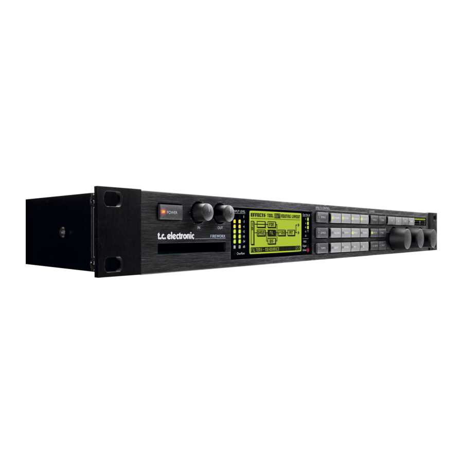
Page 6: Front Panel
3 seconds, level of Left and Right is the overall bypass. With this key you then release to power off. inputs. can bypass all effects in the FireworX OVERFLOW LED simultaneously. IN/OUT KNOBS This LED indicates ALPHA MOD. SETUP The overall analog Input level internal overflow. -
Page 7: The Front Panel
The Enter key is used to confirm actions, Mod. wheel or for accessing into a block. The Enter key will blink when the FireworX needs you to confirm. The Exit key is used to exit a menu, or to cancel an action. -
Page 8: Rear Panel
Pin 2 is “Hot” on all XLR’s (IEC and AES standards) External control jack can use momentary, alternating and continuous type pedals. The FireworX power supply is capable of operating at any line voltage from 100-240 Volts, 50-60Hz. Cables XLR - XLR... -
Page 9: Signal Flow
INTRODCUTION The Signal Flow Input Output Con/Pro Input Con/Pro Bypass Selector Gain Levels Gain Levels Analog Analog Outputs Inputs [balanced] [balanced] Digital Digital Input Output Gain Gain Digital Digital Output Inputs Channel select Channel select ADAT/OPTICAL ADAT/OPTICAL Modifier Flow INSERT INSERT Send Return... -
Page 10: Setups
INTRODUCTION Setups Setup The FireworX can be used in a number of applications. Therefore we present a couple of suggestions on how to connect the FireworX. Send/Return Connect the auxiliary out from your mixing console to the left or right input of the FireworX. -
Page 12: Basic Operation
If you want to store a preset with the same name, press Store to preset simultaneously. The function of the Alpha Mod. varies access the Store menu, and press Enter to confirm. The FireworX with the preset. A short description/name of the function is will now automatically store your preset in the first free User provided in the Recall display. -
Page 13: Display Overview
This overview of the pages in the FireworX shows what functions are located in which displays. Each box refers to a key on the front panel of the FireworX. The text in the upper right corner of the boxes tells you whether the parameters of that display are global or stored with the preset. -
Page 14: Recall
Recall. The Recall Display The FireworX contains 200 Factory Presets and has room for a maximum of 200 user Presets, however the actual number depends on the size of your Presets and may be less than 200. There are two different pages in the FireworX Recall display, “Preset” and “List”. They offer two ways of viewing the Presets of the FireworX. -
Page 15: Recall Exercises
Dial the Value to scroll through the Presets. Notice that the scroll through the factory Presets. While scrolling you will see FireworX only shows Presets containing the Delay block. both the preset number and the LED of the Enter key blinking, Select a Preset and press Enter to confirm. -
Page 16: Store
Preset in the first empty User space. If you want to store an edited User Preset with the same name, simply press Store and Enter. The FireworX will store the Preset in the same User Preset position. -
Page 17: Using A Memory Card
BASIC OPERATION Store The Store page “Store” page selected The Storing space The Name of the Preset Free space indicator The Name page “Name” page selected The New name of the Preset The function of the Alpha Mod. The Letterbox Select “CAP”... -
Page 18: Store Exercises
This exercise shows you how to store a Preset with the existing In this exercise we will try to name or rename a Preset and the name. When you try to store a Factory Preset, the FireworX Alpha Mod. function. - Page 19 How to delete a Preset This Exercise will describe how to delete a single Preset. The FireworX also has the ability to clear the whole User Preset bank instantly (please see the “Reset” page for further instructions). - Press the Store key to access the Store display.
-
Page 20: Effects Setup
#1. (See “Default parameter setting” in the Modifier chapter for Example: The FireworX is set up with two delay blocks, DLY1 further instructions). and DLY2. Double clicking the Delay mute key will take you... -
Page 21: Edit Exercises
EFFECTS SETUP Effects Exercise 6: How to Edit an effect block In this exercise we will edit an effect block. - Press the Effects key (if you are not already there). - Select the Edit page by using the < > Arrow keys. - Double click the Mute key of the block you want to edit (located on the front panel). -
Page 22: Routing Page
Mute mode of each block. The full Routing grid can be up to 8 by 8 spaces, and you can place any effect anywhere in the grid, however, the FireworX will not scroll through the last row unless a block is placed closer than two rows away. The size of the grid can be changed in the Layout page. - Page 23 (See Insert loop for further descriptions). Parallel or Serial Warning: The Insert loop is subject to small amounts of delay. The Effects blocks of the FireworX can be set up parallel or This could cause serious changes in the sound due to phase serial.
-
Page 24: Routing Exercises
EFFECTS SETUP Effects Exercise 7: Exercise 8: Inserting an Effect How to change a sub-algorithm There are two ways of inserting an effect. Let’s start by setting The Delay that you just inserted is a One-Tap Delay that contains up a Phaser and after that a Delay only one delay time. - Page 25 EFFECTS SETUP Effects Exercise 9: Exercise 9: Moving an existing block Moving an existing block This exercise shows you how to move an existing block to a different position in the Routing. Let’s move the Delay block that Select the Routing page we set up in Exercise 7&8 from position 2 1 to position 1 2.
-
Page 26: I/O Of The Blocks
NOTE: The Mute mode can influence the sound of the Preset change if the FireworX is set to “Effect mute - Off” in the Utility, Press Enter again while working in the block I/O Config. - Page 27 EFFECTS SETUP Effects Exercise 10: Exercise 10: Setting up Left/Right conditions and mute modes in a Setting up Left/Right conditions and mute modes in a block block Each block’s Left and Right Input and Output can be set up separately. In this exercise we will set up a Synth block to pass Select the Routing page only direct signal through the left output and only effect signal through the right output.
-
Page 28: Layout Page
EFFECTS SETUP Effects The Mem page “Tool” Selected Select “Tool” and Total amount of press Enter DSP power used The Layout page The Tool page The Layout page features a number of functions that all refer to The Tool page offers a number of different readouts and shortcuts to parameters that can be used in the Edit page on each block. -
Page 29: Layout Exercises
DSP Load Indicator wheel to mark The DSP load indicator to the far left on the Tool page is the inserting showing how much of the FireworX DSP power you are position Exercise 11: Inserting a new column using the Layout... -
Page 30: Modifiers
The FireworX has nine external Modifiers, the Alpha Mod. and Ext. 1-8. These Modifiers can be controlled by MIDI Controllers, Aftertouch, Note On/Off, Pitch Bend, MIDI Program Change, and the FireworX Ext. input 1/4” jack. This is set up in the I/O Setup, CTRL page. - Page 31 MODIFIERS Modifier The Matrix page Selected External/Internal Modifiers Parameter list Modifier and Parameter connected Transformation active The Link page Link Set lowest value Transformation Set middle value Set highest value Change curve Set reaction time Selected The Dials page Press Enter and dial Value to change Ext.
-
Page 32: Link Page
Value wheel to select a Modifier. Dial modulation sources, for example Envelope, Low when the input the Value wheel fully counter clockwise to remove a connection. signal into the FireworX is at its lowest and High when it is at its loudest. Slope... -
Page 33: Modifier Exercises
MODIFIERS Modifier Press Enter to change the External controllers simulated by the Exercise 13: two wheels. Use the Parameter wheel to select between Dial 1 or How to use the Link display 2, and press Exit when you have set the desired external This exercise gives an example on how the Link display can be controllers to be simulated. -
Page 34: Modifiers Page
The Envelope detectors are reading the dynamic variations of the has several setup possibilities. The Alpha Mod. wheel is input of the FireworX, and outputting control values according to described on page 39. that. The Envelope detectors can therefore be used on effects that you would like to respond to the input signal like dynamic filters or dynamic delay. - Page 35 MODIFIERS Modifier Connect the ENV detector to a level parameter to create LFOs 1 & 2 each have two outputs, which means that you can an extra gate. use the same LFO with different phase for different purposes. The parameters available in the Modifier Matrix are marked with an asterisk*.
- Page 36 MODIFIERS Modifier Out 2 Phase Speed* An LFO phase change causes a small delay in the second Sets the playback speed of the Freeform modifier. The defined waveform starting point. This means that out 1 and 2 start the number of samples will be played back over the amout of time current waveform at two different points.
- Page 37 Function 1&2 Range: +/- 50 cents. The Functions of the FireworX can be used for several purposes. Quantize into semitones - Makes the function approximate to the A Function contains two control inputs called Feed 1 & 2 that are semitone nearest to the incoming control value.
-
Page 38: External Loop
MODIFIERS Modifier Fine Tune - Shifts the generated frequency in increments of cents. Range: +/- 50 cents. Quantize into semitones - Makes the function approximate to the semitone nearest to the incoming control value. Feed 2 Pitch Bend - Feed 2 of the Function is used as Pitch Bender. -
Page 39: Alpha Mod
(called “Steady”). Delay The Alpha Mod. display Sets the amount of time before the Alpha Mod. starts bouncing Press the Alpha Mod. key on the frontpanel of the FireworX to back to 0. access the Alpha Mod. display. Time The display gives you an overview of the parameters controlled Sets the Bounce time, i.e. -
Page 40: Tempo
The Tempo can be tapped via the External input jack on the back The Tempo display panel of the FireworX or via a MIDI. That is setup in the I/O Tapping the Tempo key will cause the Tempo display to pop up. -
Page 41: Insert Loop
The Insert Loop The Insert loop is a unique feature that makes it possible to insert an external device into the Routing of the FireworX using the pair of I/O connectors not occupied by the FireworX’s main In and Outs. -
Page 42: System And Midi
The Level page contains the Analog, the Digital In/Out level and displays the incoming sample rate when using external clock The Signal page contains the source select of the FireworX Input and Outputs, including the External Loop and Dither. All settings of the I/O Setup are global, i.e. they do not change with the Presets. -
Page 43: Signal Page
Level page. The “Digital” LED will be The Clock parameter determines what source the FireworX is blinking if no clock is present or if the FireworX cannot lock to using as digital clock. The FireworX can use internal 44.1kHz, the incoming clock. -
Page 44: Level Page
FireworX is using AES/EBU in, This parameter enables or disables MIDI program changes on the and the Insert is set to Analog, the FireworX will send out on AES/EBU, S/PDIF and Tos link (or ADAT) simultaneously. -
Page 45: External Controllers
If set to disabled, the FireworX will act as a standard MIDI matter if it is connected to MIDI or to the pedal jack. product. - Page 46 Each bank holds every parameter setting in the Control menu. FireworX control Main Vol.- Controls the main output volume of the FireworX. Press the Enter key and move the External controller for auto detection. Tempo - Use this parameter to tap the global tempo via MIDI or the FireworX pedal input.
- Page 47 SYSTEM & MIDI I/O Setup...
-
Page 48: Utility
This function makes it possible to check the status of your PC- blocks in the Routing. Card. The FireworX will be able to display the size of the card, Pedal Type the write protection status, the number of Presets on the Card and Switches between momentary and alternating. - Page 49 SYSTEM & MIDI Utility confirm the copy operation. User Bank Preset start This parameter determines where the copy action should start in the internal User Bank. Card Bank Preset start This parameter determines where the copy action should start in the Card Bank.
-
Page 50: The Blocks
Processing power: 12-14% per block The Insert Loop Send and Return blocks apply to the The Dynamics block of the FireworX contains three different External loop set up in “I/O Setup, Signal”. Place the Send sub-algorithms: Expander/Gate, Soft Compressor, Hard block where you want to tap the sound, and place the Return Comp/Limiter. - Page 51 Example: If the input signal suddenly drops 4dB below threshold in no time with the Ratio set to 4:1 and the Attack SOFT COMPRESSOR set to 20ms, the FireworX will use 20ms to reach the gain reduction of 16dB. Threshold...
- Page 52 THE BLOCKS Ratio Threshold The Ratio of the gain reduction. Example: When the Ratio is When the input level exceeds the Threshold, the Compressor set to 4:1 it means that for every 4dB the input level rises, the will be activated. This means that the lower the Threshold, output level increases by only 1dB.
-
Page 53: Filters
THE BLOCKS Hicut Freq* Filters Sets the frequency of the Hicut Resonance filter. Number of blocks: 1 Range 150Hz-15kHz Processing power: 11-45% per block Lo Resonance* The Filter block contains five sub-algorithms: Resonance, Sets the amount of Resonance on the Locut filter. Bandpass, Phaser, Resonator and Resochord. - Page 54 THE BLOCKS triplets of the tapped tempo. 1/4 equals the BPM (tapped First band right freq* The first band’s frequency of the right channel. Tempo). The subdivisions available are, 16/1 (16 bars for performing Range: 20Hz-16kHz. one period), 8/1, 4/1, 2/1, 1/1, and 1/2-1/32 in straight, First band right bandwidth* The bandwidth of the first band’s right filter.
- Page 55 THE BLOCKS NOTE: The peak of the filters can get very loud and can easily hit the internal ceiling and thereby cause distortion. To prevent that, turn down the input level of the Filter block. Resochord The Resochord is based on the same algorithm as the Resonator.
-
Page 56: Formant
THE BLOCKS filter is relative to the Frequency of the corresponding Resonator voice The slope of the filter is 12dB/octave. The End point of the curve. Range: 0-100%. Resonance* Levels Voice 1-4* Sets the amount of resonance on the Formant filter. Sets the level of each of the four resonators. -
Page 57: Vocode
In Level* common in the early days of the digital world. In the Controls the input level of the block. FireworX this artifact is magified into an effect. Sound-wise, Out Level* the Aliasing appears as an unharmonic, fairly high frequency Controls the output level of the Drive block. - Page 58 - f2 and the dynamic range f1+f2. AGC Maxgain The FireworX performs a generalized Ring Modulator called Sets maximum gain that the AGC will add to the Carrier quadrature modulator which makes it possible to control the input signal.
- Page 59 THE BLOCKS Ring Mod. Internal This variation of the FireworX Ring Modulator provides an internal carrier sine wave generator with user controllable frequency. That means that the left and right input of the block is summed together and used as control input. The parameters available in the Modifier Matrix are marked with an asterisk*.
-
Page 60: Synth
THE BLOCKS In Level* Set the “Freq” parameter up to be controlled via Controls the input level of the block. MIDI using one of the Functions in the Modifier Out Level* Matrix, and use this block as a mini synthesizer (See Controls the output level of the Ring Modulator block. -
Page 61: Pitch
THE BLOCKS Range: 10Hz-16kHz. Highcut* Cuts off frequencies higher than the selected frequency. The filter is relative to the Frequency of the Chaos generator. The slope of the filter is 12dB/octave. Range: 0-100%. Single/Dual Voice Pitch Mix* Mixes between direct sound and effect. In Level* Controls the input level of the block. - Page 62 THE BLOCKS delay gives very small variations in pitch. These pitch dotted and triplet notes - 1/4 equals BPM (beats per minute). changes blended with the direct sound give you the Chorus If you select “Ignored” the current parameter will use the sound, while the modulated signal alone will give you a Preset value and will not be affected by the Global Tempo.
- Page 63 THE BLOCKS Golden Ratio Mod link Sets the Golden Ratio between Speed and Depth On/Off. If Enables you to bypass the internal LFO of the Flanger, and you want to create wild Chorus sounds you may want to turn control the sweep manually through the Modifier Matrix. the Golden Ratio off.
-
Page 64: Delay
THE BLOCKS Tempo Mix* The Tempo parameter sets the relationship to the global Mixes between direct sound and effect. In Level* Tempo e.g. if you set it to 1/4T the Flanger will use quarter note triplet of the tapped tempo to perform one cycle. Controls the input level of the block. - Page 65 If the Feedback parameter is set to 100%, the Tempo e.g. if you set it to 1/4T the Delay will use quarter FireworX will loop the Delay signal. note triplet of the tapped tempo to perform one cycle. 1/4 equals the BPM (tapped Tempo).
- Page 66 THE BLOCKS Highcut 1-2-3* Dual Three Tap Cuts off frequencies higher than the selected frequency. So if The Dual Three Tap Delay is capable of performing three you feel that there is too much treble in your signal, you can delay taps on each of the two delay lines.
- Page 67 THE BLOCKS NOTE: The sum of the six feedbacks are limited to 100%. Lowcut* Cuts off frequencies lower than the selected. The slope of the Levels 1-6* Sets the level of each of the Six Taps. filter is 12dB/octave. Pan Position 1-6* Highcut* Cuts off frequencies higher than the selected frequency.
-
Page 68: Reverb
Processing power: 39-44% per block find the tonal balance that suits you. The Reverb in the FireworX is based on the heritage of the M5000 and M2000, and is tuned for studio use. You will hear a short spatial reverb which sounds a little like a “gated “... - Page 69 Wool - Warm - Real - Clear - Bright - Crisp - Glass and the wet signal. If you are using FireworX as an insert High factor effect this means that your direct signal goes through the FireworX.
-
Page 70: Pan
Wool - Warm - Real - Clear - Bright - Crisp - Glass - Extreme. Mix* This parameter sets the mix relation between the dry (direct) and the wet signal. If you are using FireworX as an insert effect this means that your direct signal goes through the FireworX. In Level* Controls the input level of the block. - Page 71 THE BLOCKS one period), 8/1, 4/1, 2/1, 1/1, and 1/2-1/32 in straight, dotted and triplet notes - 1/4 equals BPM (beats per minute). Simple/Surround Panner If you select “Ignored” the current parameter will use the The Panner changes the level of the source signal opposite in Preset value and will not be affected by the Global Tempo.
- Page 72 THE BLOCKS outputs start the current waveform at two different points. Example: If LFO phase is set 180º, the Left and Right will be exactly opposite. Number of blocks: 1 Processing power: 19-22% per block The EQ block contains two different sub-algorithms: Fixed five band parametric EQ and modulatable four band parametric EQ.
- Page 73 THE BLOCKS Mix between direct sound and effect. In Level* Controls the input level of the block. Out Level* Controls the output level of the block. Mod. Parametric The Modulatable EQ The parameters available in the Modifier Matrix are marked with an asterisk*.
-
Page 74: Appendix
WARNING: This action will destroy ALL existing User Presets in Save setup to Card the FireworX. Insert a pc-card into the card slot and press Enter twice to confirm that you want to save the setup of the FireworX. All... -
Page 75: Self Test
Select Key test by pressing Enter. The keys must be pressed in the order they are requested by the Press Exit to leave Pedal test. FireworX to pass the test. NOTE: Result of test must be “OK” if no jack is inserted. PCMCIA test Press Exit to leave Key test. -
Page 76: Troubleshooting
The sound is phasing with your direct signal. - You are running the FireworX in a parallel setup, but the Mix function in I/O Setup, Signal menu is set to “Wet”. - The Insert loop is causing phase cancellation (See Insert loop for further explanation). -
Page 77: Midi Implementation Chart
APPENDIX MIDI Implementation Chart EFFECTS PROCESSOR FireworX - January, 1998 Version 1.0 Function Transmitted Recognized Remarks Basic Channel Default 1(-16) 1(-16) Changed 1-16 1-16 Mode Default Messages Altered Note Number 1-127 True Voice 1-127 Velocity Note ON Note OFF After Touch Key’s... -
Page 78: Tech Spec
APPENDIX Technical Specifications Analog Inputs Connectors: XLR balanced (pin 2 hot) Impedance: 20 kohm Max. Input Level: +22 dBu (balanced) Min. Input Level (for 0 dBFS): -10 dBu Sensitivity: @ 12 dB headroom: -22 dBu to +10 dBu A to D Conversion: 24 bit (1 bit, 128 times oversampling) A to D Delay: 0.8 ms @ 48 kHz... - Page 79 This equipment generates, uses and can radiate radio frequency hereby declares on own responsibility that following product: energy and, if not installed and used in accordance with the FireworX Digital Signal Processor instructions, may cause harmful interference to radio communications. However, there is no guarantee that interference will not occur in a particular installation.
-
Page 80: Presets
Creepy Vocals Short and fast delay after each other Little Speaker Makes anything sound like your first transistor radio Vocal FireworX Mickey Mouse choir, Mod Wheel takes you to the bathroom Warm Phaser Advanced phaser with chorus and delay Vox Comp/Pitch/Delay... -
Page 81: Factory Presets
PRESETS Factory Presets: Name Description Name Description Ambience Comes Back A great preset for your final mix Multivibrator Phaser, Ring Modulator and Pitcher Smart Face When you want something special on your tracks Autopanner Turn up the Panner speed with the Mod Wheel Under Water Stick your head in the water 5th Spins Around Me... - Page 82 PRESETS Factory Presets: Name Description Name Description Old School Vox Little Dist! More Lift And Separate Electrosqueeze Reverse Osmosis Diffusion Grating Gargle Feedback Natty Gitleap +Octave Thin Flang>Fat Crunch Get Mean Flaming Dr Pepper 151 Rum MbiThang Dullais-Dt Robo Voice Robo-Tracker Modsquad LocustStorm...
- Page 83 PRESETS Factory Presets: Name Description Name Description Spining Around Open The Door Fall Away Spining Voices Make It Slimer Simple Reverse Less Walk Around..Walking Position Kiss My Brass Cheese In A Can Dream Space Character Airstream Oxygen Content Bandtune Verbdelay Band Tuner Room Bright>Dark...
Need help?
Do you have a question about the FireworX and is the answer not in the manual?
Questions and answers