
Related Manuals for Fanimation The Jennix FPD7943 series


Summary of Contents for Fanimation The Jennix FPD7943 series
-
Page 1: Ceiling Fan
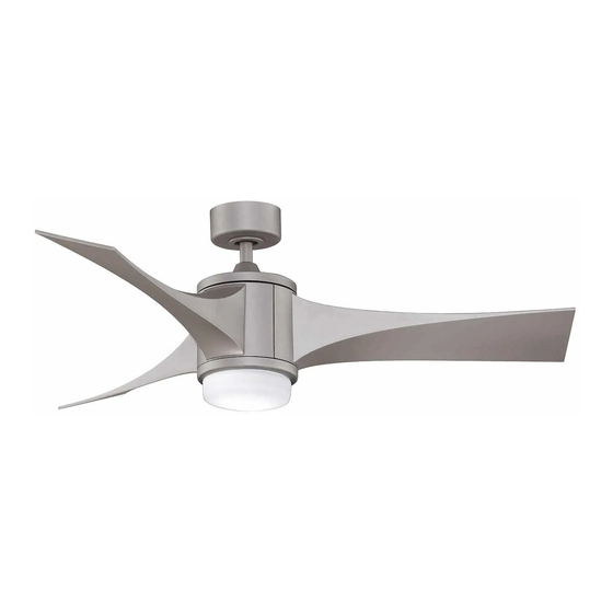
The Jennix ™ Ceiling Fan Net Weight 24.68lbs (11.21 kg) Model No. FPD7943** OWNER'S MANUAL READ AND SAVE THESE INSTRUCTIONS... -
Page 2: Important Safety Instructions
6. All costs of removal and reinstallation of the fan are the sole responsibility of the owner of the fan and not the store that sold the fan or Fanimation. 7. Fanimation reserves the right to modify or discontinue any product at any time and may substitute any part under this warranty. -
Page 3: Table Of Contents
Extends to the original purchaser of a Fanimation Fan 9. It is understood that any repair or replacement is the exclusive remedy available from Fanimation. There is no other expressed or implied warranty. Fanimation hereby disclaims any and all implied warranties, including, but not limited to those of merchantability and fitness for a particular purpose to the extent permitted by law. -
Page 4: Unpacking Instructions
Fanimation. Substitution of parts or otor Coupling Cover Assembly accessories not designated for use with this product lade Set by Fanimation could result in personal injury or Light Plate Assembly property damage. Contact your retail store for Socket Plate Assembly missing or damaged parts. -
Page 5: Energy Efficient Use Of Ceiling Fans
8 - 9 feet above the floor for optimal This produces a gentle updraft, which forces warm air airflow. Consult your Fanimation Retailer for optional near the ceiling down into the occupied space. mounting accessories. -
Page 6: How To Assemble Your Ceiling Fan
How to Assemble Your Ceiling Fan 1. Remove the hanger ball portion from the downrod/hangerball assembly by loosening the set screw in the hanger ball until the ball falls freely DOWNROD down the downrod. Remove the pin from the downrod, then remove the hanger ball. Retain the pin and hanger ball for reinstallation in Step 5 SET SCREW (Figure 1). -
Page 7: How To Hang Your Ceiling Fan
How to Assemble Your Ceiling Fan (continued) 7. Cut off excess lead wire approximately 6 to 9 inches above top of the top of the downrod. Strip 6 TO 9 insulation off 1/2-inch from the end of each lead INCHES DOWNROD wire (Figure 7). -
Page 8: How To Wire Your Ceiling Fan
How to Hang Your Ceiling Fan (continued) 4. Carefully lift the fan and seat the downrod/hanger ball assembly on the hanger bracket that was just attached to the outlet box. Be sure the groove in the ball is lined up with tab on the hanger bracket (Figure 4) WARNING Failure to seat tab in groove could cause damage to... -
Page 9: How To Install Your Canopy Housing
How to Wire Your Ceiling Fan (continued) After connections have been made, turn leads Green Wire upward and carefully push leads into the outlet White Wire from Supply from Supply box, with the white and green leads to one side (Ground) Listed Outlet Box... -
Page 10: How To Assembly The Blades & Light Kit
How to Assemble the Blades and Light Kit 1. Position the blade over the motor assembly. Make Flywheel sure the blade is fully seated against the flywheel of motor assembly. Tighten the 1/4-20 x 14 mm screws to secure the blade to the flywheel of motor assembly. (Figure 1) BLADE Figure 1... - Page 11 How to Assemble the Blades and Light Kit (continued) 5. Install included minican bulb into the socket. (Figure 5A) 5-1. Don’t install the light bulbs if you want to install the lower steel cap in Step 6-1. (Figure 5B) CAUTION To reduce the risk of fire, use 100-watt max.
-
Page 12: How To Operate Your Ceiling Fan
How to Operate Your Ceiling Fan 1. Restore electrical power to the outlet box by turning the electricity on at the main fuse box (Figure 1). WARNING MAIN FUSE BOX Check to see that all connections are tight, including ground, and that no bare wire is visible at the wire connectors, except for the ground wire. -
Page 13: How To Replace Receiver
How to Operate Your Ceiling Fan (Continued) 5. “D” and “ON” dip switch: The “ON” selection is the light dimmable selection and is to be used with all bulbs other than CFL. The “D” selection is the light on only (no dimming function) and is to be used with CFL bulbs (as CFL bulbs cannot be dimmed). -
Page 14: Trouble Shooting
Trouble Shooting WARNING For your own safety turn off power at fuse box or circuit breaker before trouble shooting your fan. Trouble Probable Cause Suggested Remedy 1. Fuse or circuit breaker blown. 1. Check main and branch circuit fuses or circuit breakers. 2. -
Page 15: Parts List
Parts List Model No. FPD7943** Ref. # Description Part # AP255BL anger Bracket Assembly w/Screws Ball-Downrod Assembly ADR1-45** Canopy PG154** anopy Screw Cover Assembly AP260** Motor Coupling Cover Assembly AP1115** Fan Motor Assembly AMA7943** Light Plate Assembly AP794306** Socket Plate Assembly... -
Page 16: Exploded-View Illustration
FPD7943** Exploded-View NOTE: The illustration shown is not to scale or its actual configurations may vary. - Page 17 10983 Bennett Parkway Zionsville, IN 46077 Toll Free (888) 567-2055 FAX (866) 482-5215 Outside U.S. call (317) 733-4113 Visit Our Fanimation Website www.fanimation.com Copyright 2012 2012/07 V.01...
- Page 18 The Jennix ™ Ventilador de techo Peso neto 24.68 lb (11.21 kg) Modelo N.º FP7943** MANUAL DEL PROPIETARIO LEA Y GUARDE ESTAS INSTRUCCIONES...
-
Page 19: Garantía Limitada De Por Vida
GARANTÍA LIMITADA DE POR VIDA DEL MOTOR - Si se produjera una falla en alguna de las partes del motor de su ventilador debido a un defecto en los materiales o en la fabricación durante el tiempo de vida del comprador original, Fanimation proporcionará la pieza de repuesto sin cargo una vez que el ventilador defectuoso sea devuelto a nuestro centro de servicios nacional. - Page 20 Se extiende al comprador original de un ventilador Fanimation Se entiende que las reparaciones y las sustituciones son el único recurso disponible de Fanimation. No existe ninguna otra garantía expresa o implícita. Por la presente, Fanimation niega todas las garantías implícitas, que incluyen, entre otras, la comerciabilidad y la aptitud para determinado fin hasta donde la ley lo permita.
-
Page 21: Instrucciones Para El Desempaque
La sustitución de piezas o accesorios no • Cubierta de unión del motor designados por Fanimation para usar con este producto • Juego de aspas podría ocasionar lesiones personales o daños en el • Ensamble de la placa de iluminación ventilador. -
Page 22: Requisitos Eléctricos Y Estructurales
óptimo. del reloj. Esto produce una suave corriente ascendente, Consulte en su tienda minorista de Fanimation para que obliga al aire cálido que se acumula cerca del techo a obtener accesorios de montaje opcionales. -
Page 23: Cómo Ensamblar El Ventilador De Techo
Cómo ensamblar el ventilador de techo 1. Extraiga la pieza de la bola colgante de la unidad de Pasador la bola colgante / varilla aflojando el tornillo de presión de la bola colgante hasta que la bola se libere de la Bola para colgar varilla. - Page 24 Cómo ensamblar el ventilador de techo (cont.) Corte el exceso de cable aproximadamente de 15 a 23 cm (6 a 9 pulgadas) por encima de la parte superior del barral. Pele 1,2 cm ( ) del aislamiento La Varilla en cada extremo del cable. (Figura 7) NOTA: Se deben revisar todos los tornillos de fijación y volver a ajustarlos cuando sea necesario antes de realizar la instalación.
-
Page 25: Cómo Realizar La Instalación Eléctrica Del Ventilador De Techo
Cómo colgar el ventilador de techo (cont.)(cont.) 4. Levante cuidadosamente el ventilador y coloque el ensamble de la bola para colgar/varilla en la abrazadera para colgar que acaba de fijar a la caja de salida. Asegúrese de que la ranura de la bola esté alineada con la lengüeta de la abrazadera para colgar. -
Page 26: Cómo Instalación De La Cubierta Del Capuchón
Cómo realizar la instalación eléctrica del ventilador de techo (cont.) Una vez realizadas las conexiones, gire los conductores hacia arriba y, con cuidado, colóquelos dentro de la Conductor blanco Conductor verde caja de salida; con los conductores blancos y verdes del suministro (puesta a tierra) Caja de salida... -
Page 27: Cómo Instalar Las Palas Y El Kit De Luces
Cómo instalar las Palas y el Kit de luces 1. Coloque el aspa en el ensamble del motor. Volante Asegúrese de del aspa esté completamente asentado sobre el volante del ensamble del motor. Apriete los tornillos con el aspa al volante del ensamble del motor. - Page 28 Cómo instalar las Palas y el Kit de luces (Cont.) 5. Introduzca la bombilla en la conexión. (Figura 5A) 5-1. No instale las bombillas si desea montar la tapa inferior de acero en el Paso 6-1. (Figura 5B) PRECAUCIÓN Para reducir el riesgo de incendios, utilice la bombilla halógena tungsteno de tipo T4-minican JD E11 de 100 Bombilla vatios máximo.
-
Page 29: Cómo Utilizar Su Ventilador De Techo
Cómo utilizar su ventilador de techo 1. Restaure la fuente de alimentación de la toma de corriente enciendo la electricidad del fusible principal. (Figura 1) ADVERTENCIA PRINCIPAL CAJA DE FUSIBLES Compruebe que todas las conexiones realizadas correctamente, incluyendo la toma de tierra, y que no se visualizan ningún cable pelado en los conectores de cables, con la excepción del cable de toma de Figura 1... - Page 30 Cómo utilizar su ventilador de techo (cont.) 4. Los botones del mando a distancia se describen a continuación: Velocidad del ventilador: I = Velocidad mínima II = Velocidad baja III = Velocidad medio baja IV = Velocidad media V = Velocidad medio alta VI = Velocidad alta Botón: Este botón apaga el ventilador.
-
Page 31: Cómo Reemplazar El Receptor
Cómo Reemplazar el Receptor 1. Retire la Cubierta de unión del motor destornillando los dos tornillos. (Figura 1) Cubierta de unión del motor Figura 1 2. Desconecte la antena, la señal de cable y conector de 9 clavijasa continuación, remplace con el receptor nuevo. -
Page 32: Solución De Problemas
Solución de problemas ADVERTENCIA Para su propia seguridad, desconecte la electricidad de la caja de fusibles o disyuntor antes de solucionar problemas en su ventilador. Problema Causa posible Solución sugerida 1. EL VENTILADOR NO 1. El fusible o el disyuntor están fundidos. 1. -
Page 33: Lista De Piezas
Lista de piezas Modelos N.° FPD7943** Pieza # N.° Descripción N.° de Ref. AP255BL Unidad del soporte de suspensión ADR1-45** Unidad del barral/de la semiesfera Capuchón de techo PG154** Cubierta para el tornillo del capuchón AP260** AP1115** Cubierta de unión del motor... -
Page 34: Ilustración Del Despiece
FPD7943** Despiece NOTA:... - Page 35 10983 Bennett Parkway Zionsville, IN 46077 Llame Sin Cargo al (888) 567-2055 FAX (866) 482-5215 Desde fuera de los EE.UU. llame al (317) 733-4113 Visite nuestro sitio Web en www.fanimation.com Copyright 2012 Fanimation 2012/07 V.01...