Advertisement
Available languages
Available languages
Quick Links
Download this manual
See also:
Owner's Manual
I
Installation
Instructions
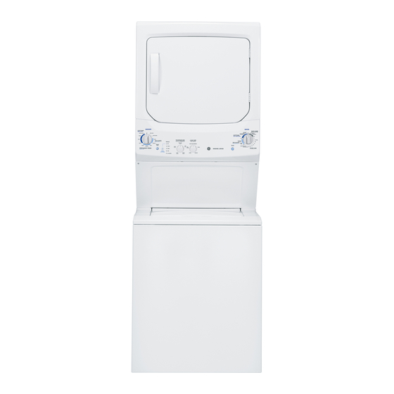
Unitized Electric
Washer/Dryer
Questions
on Installation?
Call: 1-800-GECARES (US) or Visit our Web site at: www.GEAppliunces.com
(US).
In Canada, call 888-561-3344
or visit www.GEAppliances.ca
BEFORE YOU BEGIN
Readtheseinstructions completelyandcarefully.
• IN PORTANT- savethese
instructionsfor
local inspector's use
• 1 MPORTANT-
Observeall governing codes
and ordinances.
• Note to Installer - Be sureto leavethese
instructionswith the customer.
• Note to Customer - Keepthese instructions
with your Useand CareBookfor future
reference.
• Beforethe applianceis removedfrom service
or discarded,removethe washer and dryer
doors.
• Inspectthe dryer exhaustoutlet and straighten
the outlet walls if they are bent.
• Serviceinformation and the wiring diagram
are located at the access panel.
• Donot allow childrenon or in the appliance.
Closesupervisionof childrenis necessary
when the applianceis used near children.
• Installthe appliancewherethe temperature is
above 50°Ffor satisfactoryoperation of the
control system.
,WARNING RISK O FFIRE
• To reduce the risk of severe injury or death, follow all installation
instructions.
• Appliance installation must be performed by a qualified installer.
• Install the appliance according to these instructions and in accordance
with local codes.
• This appliance must be exhausted to the outdoors.
• Use only 4" rigid metal ducting for exhausting the clothes dryer to the
outdoors.
• DO NOT install a clothes dryer with flexible plastic ducting materials.
If flexible metal (semi-rigid or foil-type) duct is installed, it must be
UL listed and installed in accordance with the instructions found in
"Connecting The Dryer To House Vent" on page 8 of this manual.
Flexible venting materials are known to collapse, be easily crushed,
and trap lint. These conditions will obstruct dryer airflow and increase
the risk of fire.
• Do not install or store this appliance in any location where it could be
exposed to water and or weather.
• Save these instructions. (Installers: Be sure to leave these instructions
with the customer).
NOTE: Installation
and service of this appliance requires
basic
mechanical
and electrical
skills. It is your responsibility
to
contact
a qualified
installer
to make the electrical
connections.
TOOLS YOU WILL NEED
Slip Pliers
Phillips Screwdriver
Flat-blade Screwdriver
1/4" Nutdriver
Level
4"DIA. METAL DUCT
(RECOMMENDED}
")
MATERIALS YOUWILL NEED
4"DUCT
4"DIA. FLEXIBLE
METAL (SEMI-RIGID}
CLAMPS
(2}
UL LISTED
TRANSITION
DUCT
(IFNEEDED)
OR
KFWX08X10077
(INCLUDES
2ELBOWS}
4"SPRING
CLAMPS(2}
4"DIA.FLEXIBLE
METAL ( F01L T YPE}
ULLISTED TRANSITION
DUCT
,,,j
(iF NEEDED,}
4"COVER
PLATE (IF NEEDED}
(KITWEZM454)
%
4"DIA. M ETAL
ELBOW
EXHAUST
SAFETY
HOOD
GLASSES
_
3/#'STRAIN
DUCTTAPE
GLOVES
RELIEF
ULRECOGNIZED
APPLIANCE
POWER
CORD K IT
(NOT P ROVIDED}
ULRATED
120/240V,30A
WITH 3OR 4PRONGS
IDENTIFY
THE P LUG
TYPE ASPER T HE
HOUSE RECEPTACLE
BEFORE
PURCHASING
LINE C ORD.
1 Cable Tie
PARTSSUPPLIED
oo
2 Stainer Screens/
2 Rubber Washers
Ruuber Washers
(washers may be in water hoses)
2 Washer Hoses
189D7219PO02
31-16652-1
02-11
GE
Advertisement

Related Manuals for GE GTUP270EM1WW


Summary of Contents for GE GTUP270EM1WW
- Page 1 Installation Unitized Electric Instructions Washer/Dryer Questions on Installation? Call: 1-800-GECARES (US) or Visit our Web site at: www.GEAppliunces.com (US). In Canada, call 888-561-3344 or visit www.GEAppliances.ca BEFORE YOU BEGIN ,WARNING RISK O FFIRE Readtheseinstructions completelyandcarefully. • To reduce the risk of severe injury or death, follow all installation instructions.
- Page 2 Installation Instructions INSTALLATION REQUIREMENTS LOCATION ELECTRICAL REQUlREM ENTS This appliance must be installed on firm flooring to CAUTION: Before plugging in washer, read the follow- minimize vibration during spin cycle. Concrete flooring is ing electrical requirements. best, but wood base is sumcient, provided floor support CAUTION: For personal safety, do not use an meets FHA standards.
- Page 3 Installation Instructions 24" NOMINAL PRODUCT DIMENSIONS .5" Water inlets (rear) _-- 4.1" Drain outlet 32.7" (rear) _-- 4.2" • _-- 27.25"---_ 75" _, * Dimension represents door closed including handle and knobs. NOTE: With feet set at mid position, feet can be adjusted +_.375". 27"...
-
Page 4: Electrical Requirements
Installation Instructions Minimum Clearance Other Than Alcove or Closet Installation Minimum clearance to combustible surfaces and for air opening are: 0 in. clearance both sides and 1 in. rear. Consideration must be given to provide adequate clearance for installation and service. NEW HOME OR REMODELING FAUCETS/ PREPARING FOR INSTALLATION DRAIN STANDPIPE/ELECTRICAL LOCATION... - Page 5 Installation Instructions 8. Properly secure power cord to strain relief. GROUNDING INSTRUCTIONS (Cont.) 9. Reinstall the cover. Do not modify the plug provided with the appliance. If it will not fit the outlet, have a proper outlet installed by a WARNING: NEVER LEAVE THE qualified electrician.
- Page 6 Installation Instructions EXHAUST INFORMATION (cont) 131EXHAUST INFORMATION EXHAUST SYSTEM CHECK LIST _4LWARNING -IN CANADA AND IN HOOD OR WALL CAP • Terminate in a manner to prevent back drafts or entry THE UNITED STATES, THE REQUIRED of birds or other wildlife. HAUST DUCT DIAMETER IS 4 IN (102mm).
- Page 7 Installation Instructions STANDARD REAR EXHAUST I-4-1 EXHAUST CONNECTION {Vented above floor level} - WARNING - TO REDUCE THE RISK OF FIRE OR PERSONAL INJURY: • This appliance must be exhausted to the outdoors. ELBOW HIGHLY • Use only 4" rigid metal ducting for the home exhaust RECOMMENDED duct.
- Page 8 Installation nstructions CONNECTING THE DRYERTO HOUSE VENT RIGIDMETAL TRANSITION DUCT • Forbest drying performance,a rigid metal transition duct is recommended. • Rigidmetal transitions ducts reducethe risk of crushing and kinking. UL-LISTED FLEXIBLE METAL (SEMI-RIGID) TRANSITION DUCT ELBOW HIGHLY • If rigid metal duct cannot be used,then UL-listedflexible metal RECOMMENDED (semi-rigid) ducting can be used(KitWX08X10077).
- Page 9 Installation Instructions ADDING ELBOW AND DUCT FOR I-6-1DRYER EXHAUST TO RIGHT, LEFT EXHAUST TO LEFT OR RIGHT SIDE OF OR BOTTOM CABINET CABINET • For side ducting, remove the knockout (ONLYZ). -/kWARNING - BEFORE PERFORMING Rotate elbow sections so that the points to the side. THIS EXHAUST INSTALLATION, BE SURE TO Preassemble 4"...
-
Page 10: Drain Requirements
Installation Instructions I-_PLUMBING INFORMATION r8-1CONNECTING TO PLUMBING FACILITI ES WATER SUPPLY REQUIREMENTS • HOTAND COLDWATERFAUCETS - Hust be within 42" of the appliance water inlet hose connections. The faucets must be 3/4" garden hose-type so inlet hoses can be connected. •WATERPRESSURE - Hust be between 10 and J_20 pounds per square inch with a maximum unbalance pressure, hot vs. -
Page 11: Door Ventilation Opening
Installation Instructions I-9-1MOBILEOR MANUFACTURED HOME DOOR VENTILATION OPENING (27" INSTALLATION MODELS) • Installation MUST conform to the MANUFACTURED A minimum of 120 square inches of opening, equally HOME CONSTRUCTION &, SAFETY STANDARD, divided at top and bottom, is required. Air openings are TITLE 24, PART 32-80 or, when such standard is not required to be unobstructed when a door is installed. - Page 12 Installation Instructions SERVICING - WARNING- LABEL ALL WIRES PRIOR TO DISCONNECTION WHEN SERVICING CONTROLS. WIRING ERRORS CAN CAUSE IMPROPER AND DANGEROUS OPERATION AFTER SERVICING/INSTALLATION. For replacement parts and other information, refer to Owner's Manual for servicing phone numbers. TO REGISTER YOUR DRYER CALL TOLL-FREE 1-888-269-1192 In Canada call 888-561-3344...
- Page 13 Instructions Laveuse/S( cheuse D'lnstallation Electriques Unifi6es Question sur I'installation? Appelez au 888.561.3344 (Canada) Ou visitez notre site web" www.electromenagersge.ca AVANT DE COMMENCER ATTENTION RIESOUE D'INCENDIE Lisez les instructions compl_tement et avec •PourreduireJes risques de blessures gravesou de mort,suivezJes instructions attention. d'instatlation.
- Page 14 Instructions d'lnstallation CONDITIONS D'INSTALLATION CONDITIONS ELECTRIQUES DEUEM PLACEMENT PRUDENCE: Avant de brancher la laveuse, lisez les conditions electriques suivantes. Cet appareil doit @tre install6 surun sol solide pour minimiser les vibrations durant le cycle d'essorage. Le sol PRUDENCE: Pour votre propre s6curit6, n'utilisez en b@on est meilleur, mais une base en bois est suff]sante.
- Page 15 Instructions d'lnstallation DIMENSIONS NOMINALES DU PRODUIT 24" '_'23.75"-_ O tol oo Ventilation _..._ 8.2" 51 ° Entrees I'eau 1" (Arri_re) _-- 4.1" 37" 26" vidange 32.7" Sortie de (Arriere)_ 4.2" 19.1" _25.75"_ 27.25"-_ * Dimensions Iorsque les portes sont ferm#es incluant les poign#es et les boutons NOTE' Dimensions en pieds, correspondant 6 _+ 575".
- Page 16 Instructions d'lnstallation Espace Minimum Autre Que le Renfoncement ou I'installation Dans un Meuble L'espace minimum pour les surfaces combustibles et I'ouverture d'air sont : 0 in. d'espace de chaque cot6 et 1 in. 5 I'arri_re. Les consid@ations doivent _tre donn6es pour fournir un espace ad6quat pour I'installation et la r6paration. NOUVELLE MAISON ET ROBINETS REMODELES I-_ SE PREPARER POUR L'INSTALLATION / LETUYAU DE VIDANGE A UEGOUT/...
- Page 17 Instructions d'lnstallation 8. Assurez la connexion du cordon @lectriqueau INSTRUCTIONS DE MASSE (suite) serrecable. Ne pas modifier la fiche fournie avec I'appareil - si elle 9. R6installez le couvercle. n'entre pas dans la prise, faites installer une prise ad#- quate par un #lectricien qualifi#. __4L ATTENTION :NE JAMAIS Pour un appareil branch# en permanence:...
- Page 18 Instructions d'lnstallation LISTE DE CONTROLE DU SYSTEME INFORMATION D'ECHAPPEMENT D'ECHAPPEMENT ATTENTION - AuCANADA CAPUCHON OU GRILLE DU MUR • Prot#gez la sortie de votre canalisation dans le but ETAUX USA, LE DIAMETRE DU TUYAU d'#viter les appels d'air ou I'entr#e d'un oiseau et autres D'ECHAPPEMENT REQUISEST 4"...
- Page 19 Instructions d'lnstelletion ECHAPPEMENT ARRIERE STANDARD I%-IBRANCHEMENT DE L'ECHAPPEMENT (Ventil_ clu-dessous du niveclu du sol} ATTENTION - POUR REDUIRELES COUDE HAUTEMENT RECOMMANDE RISOUES D'INCENDIE OU DE BLESSURES PERSONNELLES • Cet appareil dolt avoir un syst6me d'6chappement vers I'ext6rieur. • Utilisez seulement de la tuyauterie rigide en m6tal de 4"...
- Page 20 Instructions d'lnstallation BRANCHER LA SECHEUSE A L'AERATION DE LA MAISON TUYAU RIGIDE DE TRANSITION EN METAL • Pour les meilleures performances de sechage possibles, le tuyau de transition rigide en metal es trecommande. Fil RE • Les tuyaux de transition rigides en m_tal r_duisent le risque d'_crasement et de noeuds.
- Page 21 Instructions d'lnstallation AJOUTER LE COUDE ET LE TUYAU POUR 1-6-1ECHAPPEMENT DE LA SECHEUSE PAR L'ECHAPPEMENT PAR LA GAUCHE OU PAR LA LA DROITE, PAR LA GAUCHE OU PAR DROITE DU COFFRAGE LE HAUT DE COFFRAGE • Pour Io canalisation de cot6, enlevez le cache (SEULEMENT 1).
- Page 22 Instructions d'lnstallation I-7-11NFORMATION SUR LA PLOMBERIE [8-1BRANCHER LA PLOMBERIE CONDITIONS DE UAPPROVISIONEMENT EN • ROBINETSD'EAUCHAUDE ETFROIDE- IIsdoivent @tre6 moins de 42" des branchements de I'appareil pour I'arriv@ed'eau. Les robinets doivent @tresA"de la tuyauterie du jardin afin que les tuyaux internes puissent @trebranch6s.
- Page 23 Instructions d'lnstallation VENTILATION DE L'OUVERTURE DEPORTE INSTALLATION POUR LES MOBILES (MODELES 27") HOMES Unminimum de 120Sq.In. d'ouverture,divis66 part 6galeen haut et • L'installation DOlT _tre conforme aux STANDARDSDE en bas, est requis.Lesouverturesd'air sont tenues d'etre d_gag_es Iorsqu'uneporte est install_e.Uneporte persienneavec d'ouverturesd'air CONSTRUCTION ETDE SECURITE DU MOBILEHOME,TITRE _quivalentessur toute la Iongueurde la porte est acceptable.
- Page 24 Instructions d'lnstallation 1121REPARATION ATTENTION - MAROUEZ TOUSLES FILS AVANT LE DEBRANCHEMENT LORSOUE VOUS EFFECTUEZ UN CONTROLE POUR REPARATION. LES ERREURS DE BRANCHEMENT PEUVENT CAUSEES DES PROBLEMES DE FONCTIONEMENT APRES REPARATION ET D°INSTALLATION. Pour les pisces de rechange et autres informations, veuillez reporter au Manuel de I'Utilisateur pour les num6ros de...
- Page 25 Instrucciones de Secadora Unificada a Instalaci6n Lavadora/El6ctrico la Instalaci6n? i Preguntas sobre Llame al: E-800-GECARES (US} 0 visite nuestro sitio web en: www.GEAppliances.com (US; _Zk A DVERTENCIA ANTES DE COMENZAR RIESGO DE INCENDIO Lea estas instrucciones en su totalidad y •...
- Page 26 Instrucciones de Instalaci6n SERINFERIOR A 30 PULGADAS, o no m(_sde 6 pies sobre REQUISITOS DE INSTALACION UBICACION la base de la lavadora. Eltubo de subida debe ser de un Este electrodom6stico se debe instalar en un piso firme a fin de minimizar la vibraci6n durante el ciclo de minimo de 1-1/2 pulgadas dentro del di6metro y deber6 estar abierto a la atm6sfera.
- Page 27 Instrucciones de Instalaci6n DIMENSIONES NOMINALES DEL PRODUCTO DE 24" _--'23.75"---_ 43"_ • 0 Ventilaci6n _._.. 51°_ • T _]._ Entradas de agua (trasera) j_-- 4.1" 37" 327L • _Sahda de drenoje -IT ..(trasera) _--- 4.2" 27.25"---_ 23.75" -_, * La dimensi6n representa la puerta cerrada incluyendo la manija y las perillas. NOT#,: Con las patas en la posici6n intermedia, 6stas se pueden ajustar en _+.375".
- Page 28 Instrucciones de Instalaci6n Claros Minimos para Instalaci6n que no Sea Alcoba o CI6set Los claros m[nimos para superficies combustibles y al aire libre son: 0 pulgadas de despeje a ambos lados y 1 pulgada en la parte trasera. Se deber6 considerar que se debe de contar con las claros adecuados para la instalaci6n y el servicio t6cnico.
- Page 29 Instrucciones de Instalaci6n INSTRUCCIONES DE CONEXION A 8. Asegure el cable de corriente al amortiguador con refuerzo. TIERRA (cont.) 9. Vuelva a instalar la tapa. No modifique el conector provisto con el aparato - si el conector no encaja en el tomacorriente, solicite a _4LADVERTENCIA: NUNCA un electricista calificado que instale un tomacorriente adecuado.
- Page 30 Instrucciones de Instalaci6n INFORMACION SOBRE EL ESCAPE INFORMACI6N SOBRE EL ESCAPE LISTA DE CONTROL DEL SISTEMA DE ESCAPE ADVERTENCIA EN CANAD/_Y CAMPANA 0 CAPERUZADE PARED EN ESTADOSUNIDOS, EL DI/_METRODEL CONDUCTO • Terminar de modo que seeviten r6fagas de aire traseraso la DE ESCAPEREOUERIDOESDE 4"...
- Page 31 Instrucciones de Instalaci6n ESCAPE TRASERO ESTAN DAR F-_ CONEXI6N DEL ESCAPE (Ventilaci6n por encima del nivel del piso) ADVERTENCIA- PARAREDUCIR CODO ALTAMENTE EL RIESGO DE INCENDIO 0 LESIONES RECOMENDADO PERSONALES: • Este electrodom#stico deber6 contar con un escape hacia el exterior. •...
- Page 32 Instrucciones de Instalaci6n CONE×I6N DE LA SECADORA A LA VENTILACI6N DE LA CASA CONDUCTO DE TRANSICI6N DE METALRiGIDO • Poro un mejor funcionamiento del secado, se recomienda el uso de un conducto de transici6n de metal rfgido. H_ACER • Los conductos de transiciOn de metal rfgido reducen el riesgo de que se puedan aplastar o doblar.
- Page 33 Instrucciones de Instalaci6n ESCAPE HACIA LA IZQUIERDA O DERECHA DEL I-6-ISALIDA DE LA SECADORA HACIA EL GABINETE GABINETE DERECHO, IZOUIERDO O INFERIOR • Para que el conducto salga hacia uno de los laterales, quite el separador (SOLO1).Gire las secciones del codo de modo que apunten hacia el costado.
- Page 34 33" de altura, la manguera, de manguera de drenaje; junto con las abrazaderas provistas en la mc_quina, el n0mero de pieza de GE deberc_nser usadas y, ademc_s,se DEBERAinstalar una es WH49X301.Conecte desviaci6n del sif6n en la parte trasera de la mc_quina.
- Page 35 Instrucciones de Instalaci6n ABERTURA DE LA PUERTA DE I-9-11NSTALACION EN CASA RODANTE 0 VENTILAClON (MODELOS DE 27") PREFABRICADA Serequiereun minimo de 120 pulgadascuadradas de abertura, • La instalaci6n DEBEser realizada conforme con el ESTANDAR equivalentementedivididosen !o portesuperior e inferior.Se requiereque DE CONSTRUCCION Y SEGURIDADDE CASASPREFABRICADAS, losaberturas de aire no est_nobstruidas cuandose instale una puerta.
- Page 36 Instrucciones de Instalaci6n I-_SERVICIO TI_CNICO ADVERTENCIA- ETIOUETE TODOS LOS CABLES ANTES DE LA DESCONE×ION CUANDO SE REALICEN CONTROLES DEL SERVICIO TI_CNICO. CUALOUIER ERROR DE CABLEADO PUEDE OCASIONAR UN FUNCIONAMIENTO INADECUADO Y PELIGROSO LUEGO DE LA INSTALACION/SERVICIO TI_CNICO. Para el reemplazo de piezas y otras informaciones, consulte los n0meros telef6nicos...
Need help?
Do you have a question about the GTUP270EM1WW and is the answer not in the manual?
Questions and answers