GE Monogram ZV900 Installation Instructions Manual
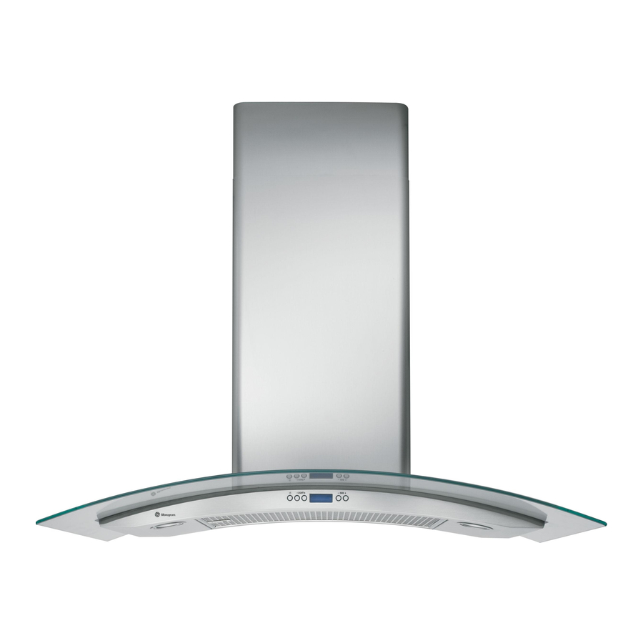
36" glass canopy chimney vent hood
Hide thumbs
Also See for Monogram ZV900:
- Installation instructions manual (21 pages) ,
- Owner's manual (16 pages) ,
- Owner's manual (12 pages)
Table of Contents
Advertisement
Quick Links
Download this manual
See also:
Owner's Manual
Advertisement
Table of Contents

Related Manuals for GE Monogram ZV900


Summary of Contents for GE Monogram ZV900
- Page 1 36" Glass Canopg Chimneg Vent Hood ZV900 Monogram: 49-80328 04-06 JR...
- Page 2 Drill 2 (two) 3/16" pilot holes through studs or rear wall support 0_"__ OCEDO 14-5/8" to top of bracket REAR WALL MOUNTING TEMPLATE ALIGN BOTTOM EDGE WITH PENCIL LINE, INDICATING BOTTOM OF THE HOOD 49-80405 04-06 JR...
- Page 3 Safety Information BEFORE YOU BEGIN WARN ING: TO REDUCE THE RISK OF FIRE, Read theseinstructions completelg and carefullg. ELECTRICAL SHOCK OR INJURY TO PERSONS, OBSERVE THE FOLLOWING: •IMPO RTANT -Save these instructions A. Use this unit only in the manner intended by the local inspector's use.
-
Page 4: Table Of Contents
Design Information CONTENTS Design Information In stallation--Recirculating Product Dimensions and Clearances ............ Ductwerk, Wiring Locations ..............Installation Options ..................Step i, Install Framing for Hood Support .......... 15 Installation Preparation Step 2, Install Mounting Bracket ............Advance Planning, Ductwork, Framing .......... - Page 5 Preparation Installation ADVANCEPLANNING • Determine the exact location of the vent hood. • Use metal ductwork onlg. These hoods must use 8" round duct. • Plan the route for venting exhaust to the outdoors. Use the shortest and straightest duct route possible.For Install a wall cap with damper or roof cap at the exterior satisfactorU performance, duct run should not exceed 100 ft.
-
Page 6: Installation Preparation
8" round *Actual length of straight duct plus duct fitting equivalent. Equivalent length of duct pieces are Total Duct Run, based on actual tests conducted by GE Evaluation Engineering and reflect requirements for good venting performance with any ventilation hood. -
Page 7: Tools And Materials
Preparation Installation TOOLS AND MATERIALS REQUIRED INOT SUPPLIED) Gloves [] Tape measure [] Knife Spirit level [] Spirit level Measuring tape [] Wire cutter/stripper Knife [] Wire nuts [] Electric drill with 5/16" and 3/8" bits [] Phillips and flat blade screwdrivers [] Hammer Pliers [] Pliers... -
Page 8: Determine Installation Height
24" to 30" 24" to 30" ACCESSORIES: 24" to 30" 24" to 30" i0'i" • Order ZX90010 accessorg for ZV900 wall mount 25" to 30" 24" to 30" i0'2" hood to reach ceiling heights between 9' 6" and 26" to 30"... - Page 9 Preparation Installation CHECK INSTALLATION HARDWARE Locate the hardware accessorg box packed with the hood and check contents. HARDWARE PACKAGE Locate and count screws Air deflector for Duct bracket recirculating installation only 3 wall 2-piece decorative duct fasteners 23-7/8" cover (dimension shown 3 wood for reference only) screws...
-
Page 10: Step I, Install Framing For Hood Support
Installation Instructions INSTALLATION-VENTEDTO THE OUTSIDE INSTALL FRAMING FOR HOOD DUCTWORK0 WIRING LOCATIONS SUPPORT Determine the exact location of the vent hood. • Locate the template packed with the literature. IN PORTANT- Framing must be capable Of - Measure 36" from the floor to the top of the cooking supporting 100 Ibs. -
Page 11: Step 3, Install Duct Bracket
Installation Instructions INSTALLATION-VENTED T OTHEOUTSIDE INSTALL MOUNTING BRACKET INSTALL DUCT BRACKET This vent hood must be secured to the horizontal The duct bracket should be installed against the support or wall studs. back wall and flush with the ceiling. This bracket will hold the duct cover in place at the top. -
Page 12: Step 4, Prepare The Hood
Installation Instructions INSTALLATION-VENTED T OTHEOUTSIDE PREPARE THE HOOD • Placethe hood on a padded surface. • Carefully lay the hood on its back. • Position the motor housing at the back of the hood. • Fasten the hood to the motor housing from the Electrical connectors should face the front, with bottom, using 6 screws. -
Page 13: Step 5, Mount The Hood
Installation Instructions INSTALLATION-VENTEDTO THE OUTSIDE MOUNT THE HOOD CONNECT DUCTWORK WARNING: 2 people are required to lift and ° Install ductwork, making connections in the direction of airflow as illustrated. position the hood onto the mounting bracket. • Push duct over the exhaust outlet and damper. AVERTISSEMENT : •... -
Page 14: Step 8, Connect Electrical
Installation Instructions INSTALLATION-VENTED T OTHEOUTSIDE CONNECT ELECTRICAL Verifg that power is turned off at the source. • Remove junction box cover and knockout on the left side. WARN ING: ,f house wiring is not 2-wire Knockout with a ground wire, a ground must be provided the installer. -
Page 15: Step 10, Install Filters
Installation Instructions INSTALLATION-VENTEDTO THE OUTSIDE J91 INSTALL DUCT COVERS INSTALL FILTERS Place the decorative duct IMPORTANT: Check to be sure that the main ON/OFF switch next to the motor is in the ON covers on top of the hood. Mounting position. - Page 16 Installation Instructions INSTALLATION--RECIRCU LATING INSTALL FRAMING FOR HOOD DUCTWORK0 WIRING LOCATIONS SUPPORT • Determine the exact location of the vent hood. • Locate the template packed with the literature. IM PORTANT: capable Framing must be • Measure 36" from the floor to the top of the cooking supporting 100 Ibs.
- Page 17 Installation Instructions INSTALLATION--RECIRCU LATING INSTALL MOUNTING BRACKET INSTALL DUCT BRACKET This vent hood must be secured to the horizontal The duct bracket should be installed against the support or wall studs. back wall and flush with the ceiling. This bracket will hold the duct cover in place at the top.
- Page 18 Installation Instructions INSTALLATION--RECIRCU LATING 141 PREPARE THE HOOD 151 MOUNT THE HOOD WARN ING: 2 toliftand • Place the hood on a padded surface. are required people • Position the motor housing at the back of the hood. position the hood onto the mounting bracket. Electrical connectors should face the front, with AVERTISSEMENT :...
- Page 19 Installation Instructions INSTALLATION--RECIRCU LATING I_l SIZE AND CUT DUCT PIECE CONNECT ELECTRICAL Hold upper air deflector Verifg that power is turned off at the source. with duct connector WARN ING: ,f house wiring is not 2-wire against the ceiling. with a ground wire, a ground must be provided •...
- Page 20 Installation Instructions INSTALLATION--RECIRCU LATING INSTALL DUCT COVERS INSTALL FILTERS • Place the decorative duct Mounting IMPORTANT: Check to be sure that the main screw holes covers on top of the hood. ON/OFF switch next to the motor is in the ON NOTE: The inside piece has position.
- Page 21 1.800.444.1845. NOTE: Product improvement is a continuing endeavor General Electric. Therefore, materials, appearance specifications are subject to change without notice. Monogram: GE Consumer& hldtlstrial GE Appliances General Electric Company Louisville, KY d]225 ge com Printed in Italy ©2006 GE Company...
Need help?
Do you have a question about the Monogram ZV900 and is the answer not in the manual?
Questions and answers