Table of Contents
Advertisement
Installation ● Operation Manual
Natural Gas (NG) - Factory Default
Liquid Propane Gas (LPG) - Optional Orifice
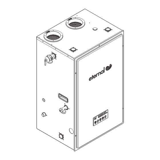
Model GU100 / 508(11,12,21,22)1100
C
Call us first if you have any questions with this product. We can help you with questions about assembly
and Water Heater operation or if there are any damaged or missing parts when you unpack this unit from the
shipping box. Please call before returning to the store.
● Only specially trained and authorized personnel are permitted to service this water heater.
●
NOTE TO ASSEMBLER / INSTALLER:
Leave this manual with the consumer.
●
NOTE TO CONSUMER:
Keep this manual for future reference.
●
RECORD YOUR SERIAL #________________
(see silver CSA label on Gas Water Heater)
!
Read this Operator's Manual carefully and be sure your Water Heater is properly assembled, installed and
maintained. Failure to follow these instructions exactly could result in fire, explosion, serious bodily injury and/or
property damage.
Do not store or use gasoline or other flammable vapors and liquids in the vicinity of this or any other appliance.
!
California Proposition 65 lists chemical substances known to the state to cause cancer, birth defects, death,
serious illness or other reproductive harm. This product may contain such substances, be their origin from fuel
combustion (gas, oil) or components of the product itself.
!
Only a licensed professional can install Eternal units for safety and code compliance. Venting and plumbing
codes can vary by location. Installation instructions and all applicable codes must be followed or property
damage, severe injury, or death may result. Failure to use a licensed plumber or contractor, follow venting,
plumbing, and building codes; or follow installation instructions may be unlawful and will void the product
warranty. Grand Hall is not responsible for any costs incurred for repairing any problems resulting from failure to
follow installation instructions or applicable codes.
Service Information Center:
1-866-946-1096
8am-4pm CST, Monday through Friday
IMPORTANT:
WARNING
WARNING
WARNING
1
157290081P Date 2011/12/15
!
!
!
Advertisement
Table of Contents

Related Manuals for Eternal GU100/508111100


Summary of Contents for Eternal GU100/508111100
- Page 1 (gas, oil) or components of the product itself. WARNING Only a licensed professional can install Eternal units for safety and code compliance. Venting and plumbing codes can vary by location. Installation instructions and all applicable codes must be followed or property damage, severe injury, or death may result.
-
Page 2: Table Of Contents
Table of Contents Included & Optional Accessories Specifications Dimensions Parts & Service Parts List P6~8 Pre-Installation Instructions for Your Safety Installation Preparation Condensate Disposal Indoor & Outdoor Installation P12~13 Mobile Home Installation & EC Adapter Installation Wall & Floor Mounting P15~16 Venting Intake &... - Page 3 Self Tapping Screw Neutralizer Kit 5/32" x 5/8" : 2pcs Water Heater 314080136 Water Heater 314080136 Stand Stand ECHNR01 Eternal Condensate Neutralizer Refill ECHNR01 Eternal Condensate Neutralizer Refill Philips Head Screw M8x15 : 4pcs Stainless Steel Expansion Bolt : 4pcs...
- Page 4 Eternal Hybrid Water Heater Technical Specifications Model Name GU100 96% NG / 97% LP / 0.94 Energy Factor Thermal Efficiency ( ) / Energy Factor Installation Indoor / Outdoor / Wall Hung / Floor Standing Flue System Forced Exhaust Power or Direct Vent Vent Run 3"...
- Page 5 Dimensions - GU100 / 508(11,12,21,22)1100...
- Page 6 Parts Diagram for Model GU100 / 508(11,12,21,22)1100...
- Page 7 Parts Diagram for Model GU100 / 508(11,12,21,22)1100...
- Page 8 Parts List for Model GU100 / 508(11,12,21,22)1100 DESCRIPTION Panel, Front Assembly Panel, Top / Rear Assembly Panel, Rear Panel, Left Assembly Panel, Right Assembly (GU100) Panel, Bottom Mounting Bracket Wall Bracket Controller / Front T&P Relief Valve (Cash Acme) Vent Collar Vent Collar Packing Rubber Foot Drain Valve Assembly...
-
Page 9: Pre-Installation Instructions For Your Safety P9
Pre-Installation Instructions for Your Safety WARNING WARNING If you do not follow these instructions exactly, a fire or explosion could result causing property damage, personal injury or loss of life. Installation Codes □ The installation must conform with local codes or, in the absence of local codes, with National Fuel Gas Code, ANSI Z223.1/NFPA 54. -
Page 10: Installation Preparation P10
Installation Preparation Unpacking Your Eternal Water Heater □ Unpack the unit carefully and make sure that all accessories are put aside so they will not be lost. ● Operator's manual ● Warranty Registration Card ● Included Parts □ Inspect the water heater for possible shipping damages. -
Page 11: Condensate Disposal P11
Figure 2. NOTICE Eternal water heater will typically produce a condensate that is considered slightly acidic with a Ph content of approximately 3-4. Install a neutralizing filter if required by authority having jurisdiction (See figure 2). Direct to drain from the unit. - Page 12 □ In general these requirements specify that if the unit is installed in a confined space, there must be permanent air supply openings if Eternal isn't installed as Direct-Vent. WARNING - high elevation installations Natural gas in high altitude might contain less heating value than typical 1100 BTU/ cuft and therefore can cause improper air / gas mix leading to improper combustion.
- Page 13 Outdoor Installation Clearances From top of water heater 24 inches From back of unit 0.6 inch From front of unit 24 inches From left side of unit (gas piping side) 6 inches From side wall flue or vent connector in any direction 6 inches From right side of unit 2 inches If this unit is installed under an overhang, there must be a 24"...
-
Page 14: Indoor & Outdoor Installation
Eternal water heater must be used as sealed combustion type (Direct Vent) where all the combustion air is supplied from the outdoors through the air intake and all combusted gas by products are vented directly to the outside by means of the vent termination. - Page 15 Wall Mounting WARNING The water heater must be properly supported; if the wall is not strong enough, be sure to reinforce the wall. The unit must be mounted on a vertical wall and level to the ground. Mounting Steps 1. Install mounting brackets with 6 screws on top and bottom back of the unit. Philips Head Screws 1/4"x3/8"...
- Page 16 Secure the unit to the wall with included wall mount bracket. Be sure to install the wall mount bracket to the wall studs. CAUTION If local codes require the water heater to be raised 18" above floor, installing GU100 on the optional Eternal Water Heater Stand (P/N 314080136) will satisfy code. In conjunction, the unit on stand raises the FVIR compliant igniter and burner at least 18"...
-
Page 17: Venting Intake & Exhaust Material P17
The supplied vent connectors are certified as part of the water heater. WARNING If the Eternal combustion air inlet is located in an area likely to cause or contain contamination, the combustion air must be repiped and terminated at another location. Contaminated combustion air will damage the unit and its... -
Page 18: Venting Specification P18
Venting Specification Direct Vent □ GU100 is factory configured as a sealed combustion unit with dedicated intake and exhaust connections. □ When installed as a Direct Vent appliance, all combustion air is drawn directly from outside of the home. □ Direct Vent configuration is suitable for indoor only. - Page 19 The total vertical and horizontal runs cannot exceed the maximum length with a maximum number of 90 degree elbows as specified in the table on page 18. □ Eternal can be vented straight up and a horizontal section is not required for vertical terminations.
- Page 20 Horizontal Termination Below diagrams are examples of vertical terminations. □ □ Side Wall (Direct Vent) Side Wall (Power Vent) Mortar or silicone caulk Mortar or silicone caulk 2'*2' Sheet Metal 2'*2' Sheet Metal Shieldon Brick or Shieldon Brick or Masonry Walls Masonry Walls Exhaust pipe Vent Terminal with...
-
Page 21: Clearance Requirements From Vent Terminations To Building Openings P21
Clearance Requirements from Vent Terminations to Building Openings All clearance requirements are in accordance with ANSI Z21.10.3 and the National Fuel Gas Code, ANSI Z223.1 and in Canada, in accordance with NSCNGPIC. □ Vent Clearances When Heater is Installed Indoors Maintain the following clearances to any opening in any building: ●... -
Page 22: Multiple Units Termination P22
al Termination 2) Horizontal Termination Multiple Units Termination * Multiple unit Termination 1) Vertical Termination Multiple unit Termination □ □ Vertical Terminations Horizontal Terminations Vent Termination Vent Termination Vent Termination 2) Horizontal Termination Combustion Air Termination Combustion Air Combustion Air Termination Termination Vent Termination... - Page 23 Concentric Vent Kit WARNING Failure to comply with the following warning could result in product damage or improper operation, personal injury, death, substantial property and/or warranty will be voided. □ Do not use concentric kit which are not approved by Grand Hall. □...
-
Page 24: Vent Pipe Installation & Terminator Position P24
Vent Pipe Installation & Terminator Position US Installations Description Canadian Installations Other than Direct Vent Direct Vent Clearance above grade, veranda, 1 foot 1 foot 1 foot porch, deck, or balcony Clearance to window or door that 4 feet below or to side of opening; 1 foot 3 feet may be opened... -
Page 25: Gas Supply Piping P25
Gas Supply Piping NOTICE □ This unit needs a manual gas control valve (shut-off valve) that must be connected to the unit before the gas line. □ Check the gas inlet pressure and the type of gas matching the rating plate located on your water heater. Also check to make sure your gas meter is capable of supplying sufficient BTU load to all appliances. -
Page 26: Lp Conversion P26
LP Conversion NOTICE Contact the local propane gas supplier for recommended sizing of piping, tanks and 100% lockup gas regulator. □ Adjust the propane supply regulator provided by the gas supplier for 13" w.c. maximum pressure. NOTICE LP conversion kit must be ordered from Grand Hall USA. Conversion can only be completed by a qualified professional. How to convert to LP 1. -
Page 27: Water Supply Connection P27
Do not remove the draining valve from the unit without first draining the tank. WARNING The use of galvanized or dielectric unions is prohibited for use with an Eternal water heater. Fail to comply with this warning will void warranty. -
Page 28: Condensate Piping P28
Condensate piping to Condensate pump Vent Relief Valve Discharge Line Vent stops vacuum air lock, and clean out for future if condensate line is clogged. Eternal Condensate Neutralizer Relief Valve Vent Discharge Line Eternal Condensate Neutralizer Condensate Pump 3/4" CPVC Pipe (Condensate) 3/4"... -
Page 29: Temperature And Pressure Relief Valve P29
Temperature and Pressure Relief Valve The following 3/4", maximum 150psi valves are approved by CSA for use with GU100 : - Cash Acme NCLX-5L CAUTION □ The temperature-pressure relief valve should be manually opened once a year. □ No one should be in front of or around the outlet of the temperature-pressure relief valve discharge line when in use. □... -
Page 30: Electrical Connection P30
Electrical Connection Installation Codes: Follow the requirements of the local authority having jurisdiction. In the absence of such requirements, follow the latest edition of the National Electrical Code ANSI/NFPA 70. Grounding and Surges □ Do not plug electrical power to the unit until all plumbing and gas piping is complete and the water heater has been filled with water. -
Page 31: Optional Remote Controller Installation P31~32
Optional Remote Controller Installation Pre-Installation Preparation 1. Turn off the unit and unplug power cord from wall socket. 2. Remove front panel by loosening 5 screws. 3. Open one of the pre-cut holes on either side panels of the unit and insert the hole plug. Precut Hole Wiring Instructions 1. - Page 32 Optional Remote Controller Installation Configuring Multiple Remote Controllers Rear Side Remote Controller Selection Switch Setting Layout 1 : Left 2 : Left Kitchen 3 : N/A 4 : N/A 1 : Right 2 : Left Bathroom 1 3 : Left 4 : N/A 1 : Right 2 : Left...
- Page 33 Recirculation System with an Eternal Water Heater Expansion Tank Cold Water Supply Fixtures Line Strainer Aquastat Aquastat should set to 20°F below Eternal temperature setting. Circulation Pump These diagrams are for reference as basic guides. Each installation should be engineered properly and compliant to Local and State Codes.
-
Page 34: Operating Instructions P34
Operating Instructions Before Starting The System □ This water heater does not have a pilot. It is equipped with an ignition device which automatically lights the burner. Do not try to light the burner manually. □ Before operating, make sure that a gas leak is not evident by smelling the area around the unit. Be sure to smell next to the floor because gas is heavier than air and will settle on the floor. -
Page 35: How To Use The Front Control Interface P35
How To Use The Front Control Interface Digital Monitor: Burner Indicator: Indicates set water temperature and Indicates when burner is in operation. shows error code in the event of an error. ON Indicator: Indicates unit is plugged in and functional. Priority Indicator: Indicates which controller is in control of adjusting... -
Page 36: How To Use The Remote Controller P36
How To Use the Remote Controller LCD Monitor: Indicates water temperature and shows error code in the event of an error. Priority Button: Alternates the control of temperature selection between front and remote Temperature Setting Button: controller. Used to set water temperature. Power Button: Turns the heater ON or OFF. -
Page 37: Maintenance And Service P37
Maintenance and Service WARNING Turn off the electrical power supply, the manual gas control valve, and the manual water control valve before servicing. SYSTEMS AND PARTS CHECK □ The unit should be checked once a year or as necessary by a certified and trained technician. If repairs are needed, the repairs should be done by a certified and trained technician. - Page 38 "D" button Diagnostic Function Applicable Model: GU100 / 508(11,12,21,22)1100 Description: Enhanced diagnostic functions are now available with the touch of a button. Simply press the “D” button on the front control panel to access features such as: inlet and outlet temperatures, air temperature inside the chassis, fan motor RPMs, error code history and more! Press the “D”...
-
Page 39: Diagnostics
DIAGNOSTICS Before calling for service, review the following diagnostic steps first for saving time and money! Question Answer Burner does not ignite when 1. Make sure that the ON/OFF button on the front or remote controller has been the hot water is opened. turned ON. -
Page 40: Self Monitoring
DIAGNOSTICS Self Monitoring This unit has the ability to check its own operation continuously. If an error occurs, a message will flash on the digital monitor of the front panel. This assists with diagnosing the error, and may enable you to overcome a problem without a service call. Please quote the code displayed when inquiring about service. - Page 41 DIAGNOSTICS ● Error Code Diagnosis Code display Cause Remedy Rotation of a DC fan is □Call service center □ too low A controller failure □Call service center □ concerning gas valve Communication failure with □Call service center □ SUB CPU Subsidiary RAM failure □Call service center □...
-
Page 42: How To Check Gas Combustion
If the combustion levels are not within the range given in Table 1 for the firing rate, shut the unit and contact Eternal Engineering support team. Failure to comply with this requirement could result in severe personal injury, death or substantial property damage. - Page 43 How To Check Gas Combustion Setting procedure for high firing Unscrew the EC adopter cap on vent collar (see to above diagram) and connect the flue gas analyzer. Set to full load: with the unit at 130°F or higher, force the unit into high fire by opening demand of at least 7 GPM water flow rate.
- Page 44 Wiring and Connection Diagram Wiring Diagram MODEL : GU100 / 508(11,12,21,22)1100 BK Y Y BK 9 10 11 12 9 10 11 12 11 12 13 13 14 15 16 17 18 19 20 21 22 23 24 13 14 15 16 17 18 19 20 21 22 23 24 BR G 120V, 60Hz...
-
Page 45: Grand Hall Limited Warranty
Grand Hall Limited Warranty General Terms of Limited Warranty for Product Grand Hall will warrant to the purchaser of this gas water heater at the ORIGINAL INSTALLED LOCATION that it will be free of defects in material, workmanship and performance when used with Potable Water* and when installed and used in strict compliance with Grand Hall’s specifications, for the applicable period shown in Warranty Periods section. - Page 46 F.A.C.T. (Factory Authorized Contractor Trained) – A licensed contractor who has been through the basic installation class held by either an Eternal Sales Representative or Grand Hall factory personnel, who has registered his/her company on the Eternal Dashboard system, and who has passed the authorization test.
- Page 47 Residential Applications, and up to 7 grains per gallon (120ppm) for Commercial Applications. ● How to Obtain Warranty Service Please contact your licensed, authorized Eternal contractor to obtain diagnostics and warranty service for your water heater. You can find authorized contractors at www.eternalwaterheater.com. Simply enter your zip code for a listing of nearby authorized contractors.
Need help?
Do you have a question about the GU100/508111100 and is the answer not in the manual?
Questions and answers