Table of Contents
Advertisement
Quick Links
NATURAl GAS (NG) - FACToRy DEFAUlT
Liquid Propane Gas (LPG) - Optional Conversion
501 Series, Models GU20/26/28/32
505 Series, Models GU20DV/28DV/26DV/32DV
Power Vent
501 Series
www.eternalwaterheater.com
Service Manual
Direct Vent
505 Series
Call Toll Free # 866-946-1096
US Patent No 6,945,197 / © 2008 Grand Hall
Part Number: MASM01
REV051809JM
Advertisement
Table of Contents

Related Manuals for Eternal 501 Series


Summary of Contents for Eternal 501 Series
- Page 1 Service Manual NATURAl GAS (NG) - FACToRy DEFAUlT Liquid Propane Gas (LPG) - Optional Conversion 501 Series, Models GU20/26/28/32 505 Series, Models GU20DV/28DV/26DV/32DV Power Vent 501 Series Direct Vent 505 Series www.eternalwaterheater.com Call Toll Free # 866-946-1096 US Patent No 6,945,197 / © 2008 Grand Hall...
-
Page 2: Glossary
Glossary This glossary is provided to help you understand some of the technical language used throughout this service manual. Direct Current Alternating Current KiloWatt, 1,000 Watts Integrated Circuit Hertz BTU/h British Thermal Units per Hour KiloPascal, 1,000 Pascals Central Processing Unit Printed Circuit Board Potentiometer Revolutions Per Minute... -
Page 3: Table Of Contents
TABlE oF CoNTENTS Glossary ..................................Pg. 02 Introduction................................Pg. 04 About Eternal Hybrid ..............................Pg. 04 Features and Benefits ............................... Pg. 04 Dimensions ................................Pg. 05 Specifications ................................Pg. 06 • Combustion ................................Pg. 08 • Water and Pressure charts ............................. Pg. 09 •... -
Page 4: Introduction
ABoUT ETERNAl HyBRID • Capable of replacing multiple tanks with a single unit Eternal is the first and only of its kind. By combining a small • Consistent temperature and pressure of hot water storage tank with the heat exchanger, the unit delivers •... -
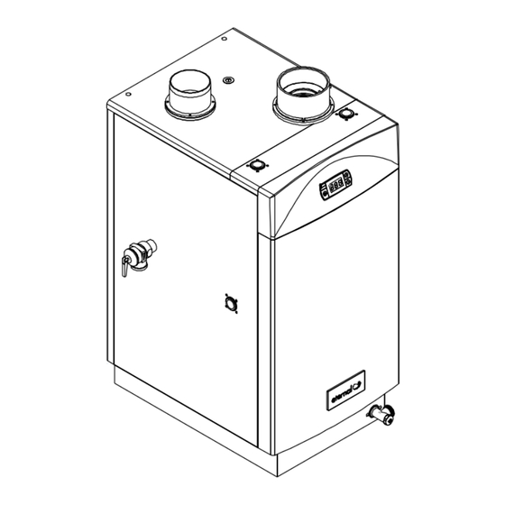
Page 5: Dimensions
DIMENSIoNS Power Vent Direct Vent... -
Page 6: Specifications
SPECIFICATIoNS Model Name GU20 (optional) GU26 GU28 (optional) GU32 Model Number (CSA) 501(11,12,21,22)1201 501(11,12,21,22)1261 501(11,12,21,22)1281 501(11,12,21,22)1321 Installation Indoor or Outdoor Type Flue system Forced Exhaust Power Vent Operation With or Without Remote Controls Ignition Direct Electronic Ignition and Automatic Flame Sensing Gas Valve Type Current Controlled Double Stage Negative Pressure Full Modulation Gas Valve Single Orifice Fuel Injection Pre-Mixing Cylindrical Metal Fiber Infrared Burner... - Page 7 GU20DV (optional) GU26DV GU28DV (optional) GU32DV 505(11,12)1201 505(11,12)1261 505(11,12)1281 505(11,12)1321 Indoor Only Sealed Combustion Direct Vent With or Without Remote Controls Direct Electronic Ignition and Automatic Flame Sensing Current Controlled Double Stage Negative Pressure Full Modulation Gas Valve Single Orifice Fuel Injection Pre-Mixing Cylindrical Metal Fiber Infrared Burner w/Full Modulation 47,500 BTU 47,500 BTU 47,500 BTU...
-
Page 8: Combustion
CHECKING GAS CoMBUSTIoN SPECIFICATIoNS Figure 1: The gas valve is designed with both test ports for gas supply pressure to the unit, and manifold pressure. Refer to Figure 1 for locations of the test ports on the gas valve. Gas Manifold Pressure Silicone Tube Regulator Adjustment Screw for Manifold... -
Page 9: Water And Pressure Charts
Flow calculation Eternal comes with built-in GPM monitor on the display. To access GPM monitor, open any tap to trigger combustion. once the combustion lED is lit and the front display shows current temperature, press either the up or down key and the display will switch to GPM mode. - Page 10 The following graph shows that Eternal can reach 7GPM with just 4.5Psi drop. The graph applies to all models and the laboratory test was conducted on 35Psi inlet supply pressure.
- Page 11 CoNTRollER DIP SWITCH SETTINGS (PoWER VENT) DIP Switch Main Controller location of DIP Switch Switch 8: NG/lPG Switch 7: Maximum gas input selection 1 Switch 6: GU20 / GU26, GU28 / GU32 Switch 5: oFF Switch 4: MCU Switch 3: Temperature section 1 Switch 2: Temperature section 2 Switch 1: Temperature section 3...
-
Page 12: Dip Switches
CoNTRollER DIP SWITCH SETTINGS (DIRECT VENT) Location of DIP Switch Location of DIP Switch DIP Switch DIP Switch KPWL01 KPWL01 RESET RESET Main Controller Default Setting Layout Main Controller Main Controller Default Setting Layout switch 8 : NG / LPG Switch 8: NG/lPG Default Setting layout switch 7 : Maximum gas input selection 1... - Page 13 limitation oF maximum temPerature By selection switcH 104°F 110°F 114°F 122°F 131°F 140°F Default Setting layout 149°F 167°F...
-
Page 14: Safety Devices
SAFETy DEVICES dry Fire Protection Freeze Protection If no flow of water in the proper direction is detected The unit’s storage contains hot water that internally circulates by the flow sensor, the unit will refuse to fire in order to to prevent the internal pipes from freezing. -
Page 15: Power Vent
CUT-AWAy VIEW (PoWER VENT) - Page 16 SCHEMATIC VIEW (PoWER VENT)
- Page 17 ExPloDED VIEW 1 (PoWER VENT)
- Page 18 ExPloDED VIEW 2 (PoWER VENT)
-
Page 19: Direct Vent
CUT-AWAy VIEW (DIRECT VENT) DV Dual Fan Dilution Tube Exhaust Collar Intake Top Thermister(Cold) Thermister(194°F) IGNITOR Mixing Control Valve Leakage Breaker(GFCI) T&P VALVE Thermister(Hot) Gas Valve Transformer Heat Exchanger Water Pressure Switch Drain Valve MAIN CONTROLLER... - Page 20 SCHEMATIC VIEW (DIRECT VENT)
- Page 21 ExPloDED VIEW 1 (DIRECT VENT)
- Page 22 ExPloDED VIEW 2 (DIRECT VENT)
- Page 23 BURNER ExPloDED VIEW...
- Page 24 MAIN CoNTRollER ExPloDED VIEW...
-
Page 25: Main Components
This unique burner also allows for pre-mix injection which has high modulation rates with just one injector. other types of burner systems use multiple injectors which can cause big pressure drop from the gas supply. Eternal can be installed on as low as just 3.5” W.C. - Page 26 This protective device is wired directly to the transformer. It provides built-in GFCI so that Fuse Eternal does not need to be plugged into a GFCI outlet. Make sure to check this device first if the unit stopped working as the breaker may have tripped or the fuse popped.
-
Page 27: Operating Principles
(over 500 steps!). The unit will produce endless hot water to meet high demand applications. Eternal is easy to install because of the hybrid design. There is no need to worry about minimum flow to trigger combustion or cold water sandwiching. The holding tank can supply hot water as soon as the tap is opening. Unlike tank-less, which has to go through a proving cycle and flush out the cold water every time a tap is turned off from on. -
Page 28: Flow Chart
oPERATIoNAl SEQUENCE FloW CHART Under 194F Error Check for Is burner on? Combustion Is H/E Temp. Error Check for Combustion lower than setting? Combustion Start Is H/E Temp. Error Check for higher than setting? Combustion Combustion Stop Combustion Error Check for w/Post Purge Start Combustion... -
Page 29: Timeline Sequence
TIME CHART Normal Ignition Sequence flow rate DC motor two poles ignitor gas valve flame signal pump time spec a (react time after start signal) b (pre-purge time) : c (pre-ignition time) : d (igintion time) : 7±1 e (max burn time) : 2h ± 10m, f (react time by controller to shut-down) : g (post-purge time) : 90 ±... -
Page 30: Symptoms And Remedies
SyMPToMS AND REMEDIES Symptom Related Parts Remedy The green lED in the leakage breaker isn’t lit System Power cord -> Check the power cord or the fuse (3A) doesn’t display temperature on a) The red lED in the leakage breaker is lit front controller leakage Breaker ->... - Page 31 Symptom Related Parts Remedy System doesn’t Flame signal plug The green lED in the leakage breaker isn’t lit detect flame -> Check the power cord or the fuse (3A) signal (Error 2 on front of controller) 22p-main-wire Pin is out of the connector ->...
- Page 32 Symptom Related Parts Remedy Error 13 No water There is no water in the H/E ( Heat Exchanger ) -> Check if H/E is filled with water Pressure switch The pressure switch has a problem -> Measure resistance of the pressure switch per Fault Diagnosis #5 Error 14,15,16 Main Controller The main controller has a problem...
- Page 33 Symptom Related Parts Remedy Error 28 Thermal Safety a) The thermostat (194F) activated Device -> Measure resistance of the thermostat (194F) per Fault Diagnosis #7 b) The thermostat (221F) activated -> Measure resistance of the thermostat (221F) per Fault DIagnosis #7 c) The thermal fuse (307F) activated ->...
-
Page 34: Fault Diagnosis
FAUlT DIAGNoSIS Fault Diagnosis #1: How to check AC voltage supplied from transformer. Set multi-meter to measure AC voltage range. Push tester pins into connector according to chosen output pins. pin no color ac voltage remark black from 102V to 132V input voltage blue over 150V... - Page 35 Fault Diagnosis #3: How to check DC voltage on 24p connector in main controller . Set multi-meter to measure DC voltage range. Push tester pin into connector according to chosen pins. pin no color remark 1, 15 blue / black inlet thermistor 2, 15 white / black...
- Page 36 Fault Diagnosis #5: How to check resistance of contacts of pressure switch. Set multi-meter to measure resistance range. Touch tester pins to a pressure sensor like figure. Normal resistance: less than 100 when water is supplied normally. Fault Diagnosis #6: How to check resistance of burner thermistor. Set multi-meter to measure resistance range.
- Page 37 Fault Diagnosis #7: How to check resistance of safety devices. Set multi-meter to measure resistance range. Push tester pins into a connector like figure. Normal resistance: less than 100 Fault Diagnosis #8: How to check resistance of a thermostat (194F). Set multi-meter to measure resistance range.
- Page 38 Fault Diagnosis #9: How to check resistance ofthermostat (221F) . Set multi-meter to measure resistance range. Touch tester pins to a thermostat like figure. Normal resistance: less than 100 Fault Diagnosis #10: How to check resistance of thermal fuse. Set multi-meter to measure resistance range. Push tester pins into connectors like figure.
- Page 39 Fault Diagnosis #11 : How to check resistance of main gas valve solenoid. Set multi-meter to measure resistance range. Touch tester pins to terminal like figure. Normal resistance: less than 2k Fault Diagnosis #12: How to check resistance of wire connected to change-over solenoid on the gas valve. Set multi-meter to measure resistance range.
- Page 40 Fault Diagnosis #13: How to check resistance of change-over solenoid. Set multi-meter to measure resistance range. Touch tester pins to terminal like figure. Normal resistance: less than 2k figure shows position of change-over solenoid when looking from back of the unit towards the front Fault Diagnosis #14: How to check resistance of wire connected to modulating solenoid on the gas valve.
- Page 41 Fault Diagnosis #15: How to check resistance of modulating solenoid on the gas valve. Set multi-meter to measure resistance range. Touch tester pins to terminal like figure. Normal resistance: less than 1k Fault Diagnosis #16 : How to measure output voltage of the leakage breaker. Set multi-meter to measure AC voltage.
- Page 42 Fault Diagnosis #17 : How to measure signal from flow sensor. Set multi-meter to mesure frequency of DC voltage. Push tester pins to connector (black and orange) like figure. Flow rate (GPM) = measured frequency ÷ 26.5 Fault Diagnosis #18 : How to measure resistance between ignition plugs. Set multi-meter to measure resistance.
- Page 43 Fault Diagnosis #19 : How to measure output voltage (or resistance) between flame signal plug and chasis. Set multi-meter AC voltage (or resistance). Touch tester pins to terminal and chassis like figure Normal Voltage: More than ACC100 V (Normal resistance: More than 100k Fault Diagnosis #20 : How to measure resistance of air pressure switch.
- Page 44 Fault Diagnosis #21 : How to measure resistance of main gas valve solenoid (lower). Set multi-meter to measure resistance. Touch tester pins to terminal like figure. Normal resistance: less than 2k Fault Diagnosis #22 : Description of gas valve. A. Change over gas valve solenoid B.
-
Page 45: Wiring Diagram
WIRING DIAGRAM (PoWER & DIRECT VENT) Direct Vent Model... -
Page 46: Electrical Component Analysis
ElECTRICAl CoMPoNENT ANAlySIS recheck wiring harness and ensure all connections are tight before performing component analysis. Power cord must be unplugged for items marked with * before analysis. Nature of Fault Examination Point Diagnostic Point Values Action A. Front Display 1. - Page 47 B. Unit does not 1. Check DIP Visual Inspection Is switch #5 pushed yes Switch it to heat water in the selection switch to “oN” position? “oFF” position tank settings on main controller Go to B-2 2. Check heat Meaure resistance [per Fault Is resistance value yes Go to B-3 exchanger...
- Page 48 D. Error 6 or 1. Check (After disconnecting Is resistance Go to D-2 Error 7 on front thermistor in thermistor from wire) reasonable as per Replace the controller heat exchanger Measure resistance [per Table 1 thermistor Fault Diagnosis #2] assembly 2.
- Page 49 G. Error 13 on 1. Check pressure Disconnect the wires on Is resistance lower yes Go to G-2 front controller switch the pressure switch and than 100 as water is measure the resistance supplied? Go to G-3 of the switch [per Fault Diagnosis #5] 2.
- Page 50 I. Error 18 1. Check main Disconnect the 2P wire Is voltage higher than yes Go to I-2 (open) on front controller connector of the burner DC 4.5V? controller thermistor on the wire Replace the bundle and measure voltage main controller between pins 14 and 15 in the 24P connector to the main controller [per Fault...
- Page 51 K. Error 20 1. Check main Disconnect 8P wire Is voltage higher than yes Go to K-2 (open) on front controller connector of the thermistor DC 4.5V controller assembly and measure Replace the voltage between pins 13 main controller and 15 (green and black) in 24P connector to the main controller [per Fault Diagnosis #3]...
- Page 52 M. Error 34 on 1. Check Measure pins 5 and 16 Is resistance higher yes Go to M-2 front controller connection quality (orange) on the 22P wire than 2k ? between change- connector to the main Replace the over gas valve and controller [per Fault main controller main controller...
-
Page 53: Dismantling For Service
DISMANTlING FoR SERVICE caution: Before proceeding with dismantling, be sure to follow the caution instructions before each step. • Shut off and disconnect from gas supply • Disconnect electrical supply from wall socket • Shut off and disconnect the water supply •... - Page 54 1) Removal of Front Panel 1. loosen the two screws on the bottom of the front panel with Phillips head screw drivers. Push the Front Panel downwards to release. 2) Removal of Main Controller 1. loosen the four screws holding the Main Controller to the frame with Philips head screw driver 3) Removal of Front Controller 1.
- Page 55 5) Removal of Mixing Valve 1. Disconenct the wire connector from the mixing valve. Pull out the two clamps holding the mixing valve in place with the water pipes to remove the mixing valve. 2. Gently wiggle the mixing valve rightwards and in a down- wards direction to release.
- Page 56 8) Removal of Leakage Breaker 1. loosen one screw to the left of the leakage breaker box holding the box to the frame with Philips head screw driver 2. loosen the four screws securing electrical wires to the leakage breaker board with Philips head screw driver 9) Removal of Flow Sensor 1.
- Page 57 3. Pull the Flow sensor towards yourself to release 10) Removal of Gas Valve 1. loosen the union connecting gas tube to the bottom of the gas valve assembly with 10” crescent wrench and discon- nect all the wire connectors. Be careful not to lose the rubber o-Ring packing.Discon- nect all the connectors.
- Page 58 11) Removal of Motor, Thermal Fuse, Burner and Burner Thermistor 1. loosen the four screws 2. loosen the two screws. Push the Top Panel backwards. 3. loosen the union by 10” crescent wrench to release. 4. loosen the two screws by 4” Phillips driver.
- Page 59 5. loosen the four screws holding the injection fan to the burner with Philips head screw driver 6. loosen the five screws holding the exhaust fan flange to the top of the exhaust hood with Philips head screw driver. Disconnect the fan’s power wire from the wiring harness 7.
- Page 60 9. loosen the eight screws by 7/64” hexagon wrench driver 10. Pull out the burner assembly upwards 11. loosen the one screw that fixes to the Burner thermistor.
- Page 61 12) Removal of Thermistor Assembly Hot Outlet Thermistor 1. loosen the nut holding the outlet thermistor to the hot wa- ter pipe by 6” crescent wrench, and be careful not to lose the rubber o-Ring. Gently pull out the thermistor by the metallic end with needle nose pliers.
-
Page 62: Modular Parts List And Diagrams For Service And Repair
MoDUlAR PARTS lIST AND DIAGRAMS FoR SERVICE AND REPAIR Diag. # Model Description Part # GU26/26DV Panel, Front 26U Assembly 301070224 GU32/32DV Panel, Front 32U Assembly 302070224 GU26/26DV Panel, Rear 26U 301040002 GU32/32DV Panel, Rear 32U 302040002 GU26/26DV Panel, Left 26U Assembly 301070225 GU32/32DV Panel, Left 32U Assembly... - Page 63 Diag. # Model Description Part # GU26/26DV Cold Water Tube A 26U 150010073 GU32/32DV Cold Water Tube A 32U 150020073 GU26/26DV, GU32/32DV Cold Water Tube B 150010074 GU26/26DV, GU32/32DV Hot Water Tube 150010075 GU26/26DV, GU32/32DV Water Fitting(SUS304) 159050270 GU26/26DV, GU32/32DV T Connector(SUS304) 159050271 GU26/26DV, GU32/32DV...
Need help?
Do you have a question about the 501 Series and is the answer not in the manual?
Questions and answers