Table of Contents
Advertisement
Installation ● Operation Manual
Natural Gas (NG) - Factory Default
Liquid Propane Gas (LPG) - Optional Ori ce
Model GU145 (S) / 508(11,12,21,22)1145 (S)
Model GU195 (S) / 508(11,12,21,22)1195 (S)
Model GU195 (M) / 508(11,12,21,22)1195 (M)
C
Call us fi rst if you have any questions with this product. We can help you with questions about assembly
and Water Heater operation or if there are any damaged or missing parts when you unpack this unit from the
shipping box. Please call before returning to the store.
● Only specially trained and authorized personnel are permitted to service this water heater.
●
NOTE TO ASSEMBLER / INSTALLER:
Leave this manual with the consumer.
●
NOTE TO CONSUMER:
Keep this manual for future reference.
●
RECORD YOUR SERIAL #________________
(see silver CSA label on Gas Water Heater)
!
Read this Operator's Manual carefully and be sure your Water Heater is properly assembled, installed and
maintained. Failure to follow these instructions exactly could result in re, explosion, serious bodily injury and/or
property damage.
Do not store or use gasoline or other ammable vapors and liquids in the vicinity of this or any other appliance.
!
California Proposition 65 lists chemical substances known to the state to cause cancer, birth defects, death,
serious illness or other reproductive harm. This product may contain such substances, be their origin from fuel
combustion (gas, oil) or components of the product itself.
!
Only a licensed professional can install Eternal units for safety and code compliance. Venting and plumbing
codes can vary by location. Installation instructions and all applicable codes must be followed or property
damage, severe injury, or death may result. Failure to use a licensed plumber or contractor, follow venting,
plumbing, and building codes; or follow installation instructions may be unlawful and will void the product
warranty. Grand Hall is not responsible for any costs incurred for repairing any problems resulting from failure to
follow installation instructions or applicable codes.
Service Information Center:
1-866-946-1096
8am-4pm CST, Monday through Friday
IMPORTANT:
WARNING
WARNING
WARNING
1
157140081P Date 2013/7/22
!
!
!
Advertisement
Table of Contents

Subscribe to Our Youtube Channel
Related Manuals for Eternal GU145 (S)/ 508


Summary of Contents for Eternal GU145 (S)/ 508
- Page 1 (gas, oil) or components of the product itself. WARNING Only a licensed professional can install Eternal units for safety and code compliance. Venting and plumbing codes can vary by location. Installation instructions and all applicable codes must be followed or property damage, severe injury, or death may result.
-
Page 2: Table Of Contents
Table of Contents Included & Optional Accessories Specifications Dimensions Parts & Service Parts List P6~10 Pre-Installation Instructions for Your Safety Installation Preparation Condensate Disposal Indoor & Outdoor Installation P14~15 Mobile Home Installation P16~18 Wall & Floor Mounting P19~20 Venting Intake & Exhaust Material Venting Specification &... - Page 3 Included Accessories Optional Accessories Self Tapping Screw 5/32" x 5/8" : 2pcs Philips Head Screw M8x15 : 4pcs Stainless Steel Expansion Bolt : 4pcs...
- Page 4 Eternal Hybrid Water Heater Technical Speci cations Model Name GU145 / GU145(S) GU195(S) / GU195(M) 98% NG / 99% LP / 0.96 Energy Factor Thermal Ef ciency ( ) / Energy Factor Installation Indoor / Outdoor / Wall Hung / Floor Standing...
- Page 5 Dimensions - GU145(S) / 508(11,12,21,22)1145(S) GU195(S,M) / 508(11,12,21,22)1195(S,M)
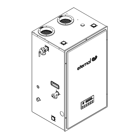
- Page 6 Parts Diagram for Model GU145(S) / 508(11,12,21,22)1145(S) GU195(S,M) / 508(11,12,21,22)1195(S,M)
- Page 7 Parts Diagram for Model GU145(S) / 508(11,12,21,22)1145(S)
- Page 8 Parts List for Model GU145(S) / 508(11,12,21,22)1145(S) DESCRIPTION Panel, Front Assembly Panel, Top / Rear Assembly Panel, Rear Panel, Left Assembly Panel, Right Assembly (GU145(S)) Panel, Bottom Mounting Bracket Wall Bracket Controller / Front T&P Relief Valve (Cash Acme) Vent Collar Vent Collar Packing Rubber Foot Drain Valve Assembly...
- Page 9 Parts Diagram for Model GU195(S) / 508(11,12,21,22)1195(S) Parts Diagram for Model GU195(M) / 508(11,12,21,22)1195(M)
-
Page 10: Parts List Gu195(S,M) / 508(11,12,21,22)1195(S,M)
Parts List for Model GU195(S,M) / 508(11,12,21,22)1195(S,M) DESCRIPTION Panel, Front Assembly Panel, Top / Rear Assembly Panel, Rear Panel, Left Assembly Panel, Right Assembly (GU195(S,M)) Panel, Bottom Mounting Bracket Wall Bracket Controller / Front T&P Relief Valve (Cash Acme) Vent Collar Vent Collar Packing Rubber Foot Drain Valve Assembly... -
Page 11: Pre-Installation Instructions For Your Safety P11
Test the water before bathing or showering. Do not leave children or the in rm without supervision. NOTE Each eternal is equipped with a computer controlled mixing valve to ensure precise temperature is being delivered. Modulation noise is normal and should not be of concern. -
Page 12: Installation Preparation P12
Installation Preparation Unpacking Your Eternal Water Heater □ Unpack the unit carefully and make sure that all accessories are put aside so they will not be lost. ● Operator's manual ● Warranty Registration Card ● Included Parts □ Inspect the water heater for possible shipping damages. -
Page 13: Condensate Disposal P13
Figure 2. NOTE Eternal water heater will typically produce a condensate that is considered slightly acidic with a Ph content of approximately 3-4. Install a neutralizing lter if required by authority having jurisdiction (See gure 2). Direct to drain from the unit. - Page 14 □ In general these requirements specify that if the unit is installed in a confined space, there must be permanent air supply openings if Eternal isn't installed as Direct-Vent. WARNING - high elevation installations Natural gas in high altitude might contain less heating value than typical 1100 BTU/ cuft and therefore can cause improper air / gas mix leading to improper combustion.
- Page 15 Outdoor Installation Clearances From top of water heater 24 inches From back of unit 0.6 inch From front of unit 24 inches From left side of unit (gas piping side) 6 inches From side wall ue or vent connector in any direction 6 inches From right side of unit 2 inches If this unit is installed under an overhang, there must be a 24"...
-
Page 16: Mobile Home Installation P16~18
Eternal water heater must be used as a sealed combustion type (Direct Vent) where all the combustion air is supplied from the outdoors through the air intake and all combusted gas byproduct is vented directly to the outside by means of the vent termination. - Page 17 Complete the rest of the vent pipe installation to the water heater's vent connector tting on the blower outlet. the table of page 22. □ Eternal can be vented straight If necessary support horizontal run as previously mentioned. up and a horizontal section is not required for vertical terminations.
- Page 18 Placement of Water Heater: Locate the water heater as desired, make certain the minimum clearances are maintained. For indoor and outdoor installation follow entire Eternal operation manual, please see section above on mobile home. "When installing in a garage, the heater's ignition source should be elevated no less the 18" from the oor."...
- Page 19 Wall Mounting WARNING □ The water heater must be properly supported; if the wall is not strong enough, be sure to reinforce the wall. The unit must be mounted on a vertical wall and level to the ground. □ Wall mount may caused noises and vibration to magnify through the wall; carefully select where to mount the unit is important.
- Page 20 6" off the floor. This mounting clearance provides access for clearing any possible debris or accumulated water seepage that can occur below the unit. Install the unit on Eternal Water Heater Stand (P/N 314080136) that raises the unit at least 6" above the floor.
-
Page 21: Venting Intake & Exhaust Material P21
The supplied vent connectors are certi ed as part of the water heater. WARNING If the Eternal combustion air inlet is located in an area likely to cause or contain contamination, the combustion air must be repiped and terminated at another location. Contaminated combustion air will damage the unit and its... - Page 22 Venting Speci cation Direct Vent □ GU145(S) / GU195(S,M) is factory configured as a sealed combustion unit with dedicated intake and exhaust connections. □ When installed as a Direct Vent appliance, all combustion air is drawn directly from outside of the home. □...
- Page 23 The total vertical and horizontal runs cannot exceed the maximum length with a maximum number of 90 degree elbows as speci ed in the table of page 22. □ Eternal can be vented straight up and a horizontal section is not required for vertical terminations.
- Page 24 Horizontal Termination Below diagrams are examples of vertical terminations. □ □ Side Wall (Direct Vent) Side Wall (Power Vent) WARNING The Grand Hall approved concentric kit is a unique pipe-in-pipe venting system designed for termination. Do not try to replicate or make your own. For more information, please refer to Concentric Vent Kit section in the Operation manual.
-
Page 25: Clearance Requirements From Vent Terminations To Building Openings P25
Clearance Requirements from Vent Terminations to Building Openings All clearance requirements are in accordance with ANSI Z21.10.3 and the National Fuel Gas Code, ANSI Z223.1 and in Canada, in accordance with NSCNGPIC. □ Vent Clearances When Heater is Installed Indoors Maintain the following clearances to any opening in any building: ●... -
Page 26: Multiple Units Termination P26
Multiple Units Termination Multiple unit Termination □ □ Vertical Terminations Horizontal Terminations WARNING The Grand Hall approved concentric kit is a unique pipe-in-pipe venting system designed for termination. Do not try to replicate or make your own. For more information, please refer to Concentric Vent Kit section in the Operation manual. -
Page 27: Common Venting Installation
Common Vent Installation Applicable Model GU195 (M) / 508 (11,12,21,22)1195 (M) Systems Common vent system is strictly applicable for GU195M model only. Only units that are connected by MCU wire with dipswitch set up on main controller board (PCB) to operate as one group can be common vented together. It is required for vent system to be perfectly impermeable to condensation and made out of corrosion resistant materials. - Page 28 Concentric Vent Kit WARNING Failure to comply with the following warning could result in product damage or improper operation, personal injury, death, substantial property and/or warranty will be voided. □ Do not use concentric kit which are not approved by Grand Hall. □...
-
Page 29: Vent Pipe Installation & Terminator Position P29
Vent Pipe Installation & Terminator Position US Installations Description Canadian Installations Other than Direct Vent Direct Vent Clearance above grade, veranda, 1 foot 1 foot 1 foot porch, deck, or balcony Clearance to window or door that 4 feet below or to side of opening; 1 foot 3 feet may be opened... -
Page 30: Gas Supply Piping P30
Gas Supply Piping NOTE □ This unit needs a manual gas control valve (shut-off valve) that must be connected to the unit before the gas line. □ Check the gas inlet pressure and the type of gas matching the rating plate located on your water heater. Also check to make sure your gas meter is capable of supplying suf... -
Page 31: Lp Conversion P31
To convert back from LP to Natural Gas All Eternal models come factory pre-configured as Natural gas, However if the water heater has been converted to LP and needs to be converted back to Natural gas, follow steps 1, 2, 3 and remove the LP ori... -
Page 32: Water Supply Connection P32
WARNING □ Eternal is designed for full ow with low pressure loss. Without ow restriction, if Eternal is overdrawn due to demand exceeding unit(s)’s BTU recovery capacity, outlet temperature will not reach set point. However, full flow without diminished hot water pressure will continue to be delivered. -
Page 33: Condensate Piping P33
Condensate piping to floor drain Condensate piping to Condensate pump Vent Relief Valve Discharge Line Vent stops vacuum air lock, and clean out for future if condensate line is clogged. Eternal Condensate Neutralizer Relief Valve Vent Discharge Line Eternal Condensate Neutralizer Condensate Pump... - Page 34 When setting unit temperature higher than 140°F for Description: commerical use or sanitation purpose, it's recommended Eternal has an optional Internal Pump Control (IPC) which to use Aquastat control or timer for the recirculation system can provide enhanced efficiencies and eliminates the need instead of using Internal Pump Control, Aquastat should be set 20°F below Eternal temperature setting.
-
Page 35: Electrical Connection P35
Electrical Connection Installation Codes: Follow the requirements of the local authority having jurisdiction. In the absence of such requirements, follow the latest edition of the National Electrical Code ANSI/NFPA 70. Grounding and Surges □ Do not plug electrical power to the unit until all plumbing and gas piping is complete and the water heater has been ... -
Page 36: Optional Remote Controller Installation P36~37
Optional Remote Controller Installation Pre-Installation Preparation 1. Turn off the unit and unplug power cord from wall socket. 2. Remove front panel by loosening 5 screws. 3. Open one of the pre-cut holes on either side panels of the unit and insert the hole plug. Precut Hole Wiring Instructions 1. - Page 37 Optional Remote Controller Installation Configuring Multiple Remote Controllers Rear Side Remote Controller Selection Switch Setting Layout 1 : Left 2 : Left Kitchen 3 : N/A 4 : N/A 1 : Right 2 : Left Bathroom 1 3 : Left 4 : N/A 1 : Right 2 : Left...
-
Page 38: Mcu Installation P38~40
MCU Installation MCU Kit Components MCU Wire Female Termination Wire (F1/Blue) Male Termination Wire (M1/Yellow) Specifications and Features Applicable Models : GU195(M) / 508(11,12,21,22)1195(M) Description: MCU kit allows multiple units to be linked together in a parallel manifold configuration. Feature and Benefits □... - Page 39 MCU Installation MCU Installation With all taps closed and unit off, unplug the power cord of the unit from the power outlet. Make sure dip switch #4 to ON position. (Group 1, No.4). Group 1 dip switches should be the same for all units connected together.
- Page 40 Power Supply Schematic Diagram Operating as a single unit, Eternal consumes less than 1A current, and the power supplied to the unit can be on as low as 2A capacity. However, when multiple Eternals are used together, the power supply requirement is significantly increased.
- Page 41 Recirculation System with an Eternal Water Heater Recirculation with 2 Units These diagrams are for reference as basic guides. Each installation should be engineered properly and compliant to Local and State Codes. WARNING Pump control such as aquastat or timer and aquastat must be used in recirculation application or short cycle may...
- Page 42 System for rapid ON/OFF and large volume usage Note 1 : If the unit is not controlling the pump by the internal relay, use a Aquastat pump and set at 20°F below Eternal temperature setting. WARNING Pump control such as aquastat or timer and aquastat must be used in recirculation application or short cycle may...
- Page 43 Plumbing System for Multiple Unit Applications NOTE This concept can be applied when two or more heaters are used in parallel, the inlet and outlet piping should be arranged in a way that an equal flow is received from each heater under all demand conditions. With a reverse return system it is easy to get parallel flow.
- Page 44 It is important to check against eternal's inlet temperature by using eternal's diagnostic function to verify that the pump does shut off when "I" reached 20°F below the setting temperature and aquastat is setup properly.
-
Page 45: Operating Instructions P45
Operating Instructions Before Starting The System □ This water heater does not have a pilot. It is equipped with an ignition device which automatically lights the burner. Do not try to light the burner manually. □ Before operating, make sure that a gas leak is not evident by smelling the area around the unit. Be sure to smell next to the ... -
Page 46: How To Use The Front Control Interface P46
How To Use The Front Control Interface To switch the water heater ON: From OFF condition Press the Power Button. □ The temperature selected will be indicated on the Digital Monitor. □ The ON Indicator will light up. When running the water by opening the water tap, the water heater will start the burner automatically and the Digital Monitor will show the Burner ON indicator. - Page 47 Fail to comply the warning will void warranty) Each Eternal water heater is equipped with built-in Ignition Cycle Counter located on the main controller board. Excessive cycles caused by improper application voids warranty. For more detail about the acceptable cycle limit,...
-
Page 48: Maintenance And Service P48
Maintenance and Service WARNING Turn off the electrical power supply, the manual gas control valve, and the manual water control valve before servicing. SYSTEMS AND PARTS CHECK □ The unit should be checked once a year or as necessary by a certified and trained technician. If repairs are needed, the repairs should be done by a certi... - Page 49 "D" button Diagnostic Function Applicable Model: GU145(S) / 508(11,12,21,22)1145(S) GU195(S) / 508(11,12,21,22)1195(S) GU195(M) / 508(11,12,21,22)1195(M) Description: Enhanced diagnostic functions are now available with the touch of a button. Simply press the “D” button on the front control panel to access features such as: inlet and outlet temperatures, air temperature inside the chassis, fan motor RPMs, error code history and more! Press the “D”...
-
Page 50: Diagnostics
DIAGNOSTICS Before calling for service, review the following diagnostic steps rst for saving time and money! - Page 51 DIAGNOSTICS Self Monitoring This unit has the ability to check its own operation continuously. If an error occurs, a message will flash on the digital monitor of the front panel. This assists with diagnosing the error, and may enable you to overcome a problem without a service call. Please quote the code displayed when inquiring about service.
- Page 52 DIAGNOSTICS NOTE: In all cases you may be able to clear the Error Message simply by turning the hot water tap OFF, then ON again. If this does not clear the Error Message, try pushing the ON/OFF button OFF, then ON again. If the Error Message still remains, contact our service center or your nearest service agent and arrange for a service call.
-
Page 53: How To Check Gas Combustion P53~54
If the combustion levels are not within the range given in Table 1 for the ring rate, shut the unit and contact Eternal Engineering support team. Failure to comply with this requirement could result in severe personal injury, death or substantial property damage. - Page 54 How To Check Gas Combustion Procedure for high ring Note : During this procedure you will only observe the reading and will not make any adjustment. Unscrew the EC adopter cap on vent collar (see to above diagram) and connect the ue gas analyzer. Set to full load: with the unit at 130°F or higher, force the unit into high ...
-
Page 55: Wiring And Connection Diagram P55~56
Wiring and Connection Diagram Wiring Diagram MODEL : GU145(S) / 508(11,12,21,22)1145(S) GU195(S) / 508(11,12,21,22)1195(S) - Page 56 Wiring and Connection Diagram Wiring Diagram MODEL : GU195(M) / 508(11,12,21,22)1195(M)
-
Page 57: Grand Hall Limited Warranty P57~59
Grand Hall Limited Warranty General Terms of Limited Warranty for Product Grand Hall will warrant to the purchaser of this gas water heater at the ORIGINAL INSTALLED LOCATION that it will be free of defects in material, workmanship and performance when used with Potable Water* and when installed and used in strict compliance with Grand Hall’s speci... - Page 58 Grand Hall Limited Warranty Limited Labor Allowance Grand Hall will provide a pre-set labor allowance as set forth in the following table, which shall be paid to the licensed contractor who obtains written authorization or a Work Order from Grand Hall in advance, strictly for repairs or replacements for warrantycovered defects occurring within one (1) year from the date of purchase.
- Page 59 F.A.C.T. (Factory Authorized Contractor Trained) – A licensed contractor who has been through the basic installation class held by either an Eternal Sales Representative or Grand Hall factory personnel, who has registered his/her company on the Eternal Dashboard system, and who has passed the authorization test.
Need help?
Do you have a question about the GU145 (S)/ 508 and is the answer not in the manual?
Questions and answers