Table of Contents
Advertisement
Quick Links
Advertisement
Table of Contents

Subscribe to Our Youtube Channel
Related Manuals for Supero SUPERSERVER 5026T-3F


Summary of Contents for Supero SUPERSERVER 5026T-3F
- Page 1 ® UPER 5026T-3F UPER ERVER 5026T-T UPER ERVER USER’S MANUAL...
- Page 2 The information in this User’s Manual has been carefully reviewed and is believed to be accurate. The vendor assumes no responsibility for any inaccuracies that may be contained in this document, makes no commitment to update or to keep current the information in this manual, or to notify any person or organization of the updates.
-
Page 3: About This Manual
F/5026T-T. Installation and maintainance should be performed by experienced technicians only. The SuperServer 5026T-3F/5026T-T is a high-end, single processor server based on the SC822TQ-400LPB 2U rackmount server chassis and the X8ST3-F/X8STE motherboard, which supports single Intel® Core™ i7 and Xeon® or future Intel Nehalem processor families (next generation Intel Xeon®... - Page 4 You should thoroughly familiarize yourself with this chapter for a general overview of safety precautions that should be followed when installing and servicing the SuperServer 5026T-3F/5026T-T. Chapter 5: Advanced Motherboard Setup Chapter 5 provides detailed information on the X8ST3-F/X8STE motherboard, including the locations and functions of connectors, headers and jumpers.
- Page 5 Preface Notes...
-
Page 6: Table Of Contents
UPER ERVER 5026T-3F/5026T-T User's Manual Table of Contents Chapter 1 Introduction Overview ......................1-1 Motherboard Features ..................1-2 Processors ...................... 1-2 Memory ......................1-2 Onboard SAS (5026T-3F only) ............... 1-2 Onboard SATA ....................1-2 PCI Expansion Slots ..................1-2 ATI Graphics Controller ................... 1-2 Onboard Controllers/Ports ................ - Page 7 Table of Contents Installing the Server into the Rack ..............2-6 Installing the Server into a Telco Rack ............2-7 Checking the Motherboard Setup ..............2-8 Checking the Drive Bay Setup ..............2-10 Chapter 3 System Interface Overview ......................3-1 Control Panel Buttons ..................
- Page 8 Onboard Indicators ..................5-23 5-12 Floppy, SAS and SATA Ports ................ 5-24 5-13 Installing Software ..................5-26 Supero Doctor III ................... 5-27 Chapter 6 Advanced Chassis Setup Static-Sensitive Devices .................. 6-1 Precautions ..................... 6-1 Unpacking ....................... 6-1 Control Panel ....................6-2 System Fans ....................
-
Page 9: Chapter 1 Introduction
Chapter 1 Introduction Overview The SuperServer 5026T-3F/5026T-T is a high-end, 2U rackmount server that fea- tures some of the most advanced technology currently available. The SuperServer 5026T-3F/5026T-T is comprised of two main subsystems: the SC822TQ-400LPB 2U chassis and the X8ST3-F/X8STE motherboard. Please refer to our web site for information on operating systems that have been certifi... -
Page 10: Motherboard Features
ERVER 5026T-3F/5026T-T Manual Motherboard Features At the heart of the SuperServer 5026T-3F/5026T-T lies the X8ST3-F/X8STE, a single Intel® Core™ i7 or Xeon processor motherboard designed to provide maxi- mum performance. Below are the main features of the X8ST3-F/X8STE. (See Figure 1-1 for a block diagram of the chipset.) -
Page 11: Onboard Controllers/Ports
Chapter 1: Introduction Onboard Controllers/Ports The X8ST3-F/X8STE includes a fl oppy drive controller and backpanel I/O ports that include one COM port, two USB ports, PS/2 mouse and keyboard ports, a video (monitor) port and dual Gigabit Ethernet LAN ports and a dedicated IPMI LAN port. A second COM port is available as an onboard header. - Page 12 UPER ERVER 5026T-3F/5026T-T Manual Figure 1-1. Intel X58 Chipset: System Block Diagram DIMM_CHA Intersil Intel DIMM_CHB VRD 11.1 LGA1366_PROCESSOR DIMM_CHC DDR3:1333/1066/800 QPI: Up to 6.40 GT/s CK505 CLK PCI_E x8 on PCIE_x8 Intel X16 Slot SAS1068E PCIE_x8 PCIE_x8 SAS x8 Tylersburg PCI_E x8 Slot PCIE_x4...
-
Page 13: Server Chassis Features
Chapter 1: Introduction Server Chassis Features The following is a general outline of the main features of the SC822TQ-400LPB chassis. System Power When confi gured as the 5026T-3F/5026T-T, the SC822TQ-400LPB chassis includes a single 400W power supply. SAS Subsystem (5026T-3F only) The SAS subsystem supports six hot-swap SAS hard drives. -
Page 14: Contacting Supermicro
UPER ERVER 5026T-3F/5026T-T Manual Contacting Supermicro Headquarters Address: Super Micro Computer, Inc. 980 Rock Ave. San Jose, CA 95131 U.S.A. Tel: +1 (408) 503-8000 Fax: +1 (408) 503-8008 Email: marketing@supermicro.com (General Information) support@supermicro.com (Technical Support) Web Site: www.supermicro.com Europe Address: Super Micro Computer B.V. -
Page 15: Chapter 2 Server Installation
Unpacking the System You should inspect the box the SuperServer 5026T-3F/5026T-T was shipped in and note if it was damaged in any way. If the server itself shows damage you should fi le a damage claim with the carrier who delivered it. -
Page 16: Choosing A Setup Location
UPER ERVER 5026T-3F/5026T-T Manual Choosing a Setup Location • Leave enough clearance in front of the rack to enable you to open the front door completely (~25 inches) and approximately 30 inches of clearance in the back of the rack to allow for suffi cient airfl ow and ease in servicing. •... -
Page 17: Rack Mounting Considerations
Chapter 2: Server Installation • Allow the hot plug SATA drives and power supply modules to cool before touch- ing them. • Always keep the rack's front door and all panels and components on the servers closed when not servicing to maintain proper cooling. Rack Mounting Considerations Ambient Operating Temperature If installed in a closed or multi-unit rack assembly, the ambient operating tempera-... -
Page 18: Installing The System Into A Rack
ERVER 5026T-3F/5026T-T Manual Installing the System into a Rack This section provides information on installing the SuperServer 5026T-3F/5026T-T into a rack unit. If the 5026T-3F/5026T-T has already been mounted into a rack, you can skip ahead to Sections 2-5 and 2-6. -
Page 19: Installing The Chassis Rails
Figure 2-2. Installing Chassis Rails Installing the Rack Rails Determine where you want to place the SuperServer 5026T-3F/5026T-T in the rack. (See Rack and Server Precautions in Section 2-3.) Position the fi xed rack rail/sliding rail guide assemblies at the desired location in the rack, keeping the sliding rail guide facing the inside of the rack. -
Page 20: Installing The Server Into The Rack
UPER ERVER 5026T-3F/5026T-T Manual Installing the Server into the Rack You should now have rails attached to both the chassis and the rack unit. The next step is to install the server into the rack. Do this by lining up the rear of the chassis rails with the front of the rack rails. -
Page 21: Installing The Server Into A Telco Rack
Chapter 2: Server Installation Installing the Server into a Telco Rack If you are installing the SuperServer 5026T-3F/5026T-T into a Telco type rack, follow the directions given on the previous pages for rack installation. The only difference in the installation procedure will be the positioning of the rack brackets to the rack. -
Page 22: Checking The Motherboard Setup
UPER ERVER 5026T-3F/5026T-T Manual Checking the Motherboard Setup After you install the 5026T-3F/5026T-T in the rack, you will need to open the unit to make sure the motherboard is properly installed and all the connections have been made. Accessing the Inside of the System Release the retention screws that secure the unit to the rack. - Page 23 Chapter 2: Server Installation Figure 2-5. Accessing the Inside of the System...
-
Page 24: Checking The Drive Bay Setup
UPER ERVER 5026T-3F/5026T-T Manual Checking the Drive Bay Setup Next, you should check to make sure the peripheral drives and the SAS/SATA drives and backplanes have been properly installed and all connections have been made. Checking the Drives All drives are accessable from the front of the server. For servicing the CD- ROM and fl... -
Page 25: Chapter 3 System Interface
Chapter 3: System Interface Chapter 3 System Interface Overview There are several LEDs on the control panel as well as others on the SAS/SATA drive carriers and the motherboard to keep you constantly informed of the overall status of the system as well as the activity and health of specifi c components. There are also two buttons on the chassis control panel. -
Page 26: Control Panel Leds
UPER ERVER 5026T-3F/5026T-T User's Manual Control Panel LEDs The control panel located on the front of the SC822TQ-400LPB chassis has fi ve LEDs. These LEDs provide you with critical information related to different parts of the system. This section explains what each LED indicates when illuminated and any corrective action you may need to take. -
Page 27: Power
Chapter 3: System Interface Power Indicates power is being supplied to the system's power supply units. This LED should normally be illuminated when the system is operating. Drive Carrier LEDs SAS Drives (5026T-3F) • Green: When illuminated, the green LED on the front of the SAS drive carrier indicates drive activity. - Page 28 UPER ERVER 5026T-3F/5026T-T User's Manual Notes...
-
Page 29: Chapter 4 System Safety
System Safety Electrical Safety Precautions Basic electrical safety precautions should be followed to protect yourself from harm and the SuperServer 5026T-3F/5026T-T from damage: • Be aware of the locations of the power on/off switch on the chassis as well as the room's emergency power-off switch, disconnection switch or electrical outlet. -
Page 30: General Safety Precautions
UPER ERVER 5026T-3F/5026T-T User's Manual • Serverboard Battery: CAUTION - There is a danger of explosion if the onboard battery is installed upside down, which will reverse its polarites (see Figure 4-1). This battery must be replaced only with the same or an equivalent type recommended by the manufacturer. -
Page 31: Esd Precautions
Chapter 4: System Safety • After accessing the inside of the system, close the system back up and secure it to the rack unit with the retention screws after ensuring that all connections have been made. ESD Precautions Electrostatic discharge (ESD) is generated by two objects with different electrical charges coming into contact with each other. -
Page 32: Operating Precautions
UPER ERVER 5026T-3F/5026T-T User's Manual Operating Precautions Care must be taken to assure that the chassis cover is in place when the 5026T- 3F/5026T-T is operating to assure proper cooling. Out of warranty damage to the system can occur if this practice is not strictly followed. Figure 4-1. -
Page 33: Chapter 5 Advanced Serverboard Setup
Chapter 5: Advanced Serverboard Setup Chapter 5 Advanced Serverboard Setup This chapter covers the steps required to install the X8ST3-F/X8STE serverboard into the chassis, connect the data and power cables and install add-on cards. All serverboard jumpers and connections are also described. A layout and quick refer- ence chart are included in this chapter for your reference. -
Page 34: Unpacking
UPER ERVER 5026T-3F/5026T-T User's Manual Unpacking The serverboard is shipped in antistatic packaging to avoid electrical static dis- charge. When unpacking the board, make sure the person handling it is static protected. Serverboard Installation This section explains the fi rst step of physically mounting the X8ST3-F/X8STE into the SC822TQ-400LPB chassis. -
Page 35: Connecting Cables
Chapter 5: Advanced Serverboard Setup Connecting Cables Now that the serverboard is installed, the next step is to connect the cables to the board. These include the data cables for the peripherals and control panel and the power cables. Connecting Data Cables The cables used to transfer data from the peripheral devices have been carefully routed to prevent them from blocking the fl... -
Page 36: I/O Ports
UPER ERVER 5026T-3F/5026T-T User's Manual Figure 5-1. Control Panel Header Pins Ground x (Key) x (Key) Power On LED HDD LED NIC1 LED NIC2 LED OH/Fan Fail LED Power Fail LED Ground Reset (Button) Ground Power (Button) I/O Ports The I/O ports are color coded in conformance with the PC 99 specifi cation. See Figure 5-2 below for the colors and locations of the various I/O ports. -
Page 37: Installing The Processor And Heatsink
Chapter 5: Advanced Serverboard Setup Installing the Processor and Heatsink When handling the processor package, avoid placing direct pressure on the label area of the fan. Notes: Always connect the power cord last and always remove it before adding, re- moving or changing any hardware components. - Page 38 UPER ERVER 5026T-3F/5026T-T User's Manual After removing the plastic cap, use your thumb and the index fi nger to hold the CPU at the north and south center edges. Align the CPU key (the semi-circle cutout) with the socket key (the notch below the gold color dot on the side of the socket).
-
Page 39: Installing An Active Heatsink
Chapter 5: Advanced Serverboard Setup Installing an Active Heatsink Locate the CPU fan connector on the motherboard. (Refer to the motherboard layout for the loca- tion.) Thermal Grease Position the heatsink so that the heatsink fan wires are closest to the CPU fan connector and do not interfere with other components. -
Page 40: Removing The Heatsink
UPER ERVER 5026T-3F/5026T-T User's Manual Note: Make sure to orient each fastener so that the narrow end of the groove is pointing outward.) Repeat Step 6 to insert all four heatsink fasteners into the mount- ing holes. Narrow end of the groove Once all four fasteners are se- should point outward curely inserted into the mounting... -
Page 41: Installing Memory Modules
Chapter 5: Advanced Serverboard Setup Installing Memory Modules Note: Check the Supermicro web site for recommended memory modules. CAUTION Exercise extreme care when installing or removing DIMM modules to prevent any possible damage. Press down the release tabs Installing & Removing DIMMs Insert the desired number of DIMMs into the memory slots, starting with DIMM #1A. -
Page 42: Memory Support
UPER ERVER 5026T-3F/5026T-T User's Manual Memory Support The X8SST3-F/X8STE supports up to 24 GB of Unbuffered ECC or Non-ECC DDR3-1333/1066/800 SDRAM in 6 DIMM slots. Populating these DIMM modules with a pair (or pairs) of memory modules of the same type and size will result in interleaved memory, which will improve memory performance. -
Page 43: Adding Pci Add-On Cards
Chapter 5: Advanced Serverboard Setup Adding PCI Add-On Cards The SC822TQ-400LPB chassis can accommodate all PCI expansion slots on the X8ST3-F/X8STE being populated with low-profi le cards. Installing an Add-on Card Begin by removing the shield for the PCI slot you wish to populate. Fully seat the card into the slot, pushing down with your thumbs evenly on both sides of the card. -
Page 44: Serverboard Details
UPER ERVER 5026T-3F/5026T-T User's Manual Serverboard Details Figure 5-4. X8ST3-F/X8STE Layout (not drawn to scale) SMBUS_PS1 JPW1 JPW2 KB/MOUSE JPUSB1 FAN1 DIMM3A CPU FAN DIMM3B USB 0/1 DIMM2A DIMM2B LAN CTRL DIMM1A for IPMI LAN DIMM1B CTRL1 JLED Intel X58 LAN1 North Bridge Intel Processor... -
Page 45: X8St3-F/X8Ste Quick Reference
Chapter 5: Advanced Serverboard Setup X8ST3-F/X8STE Quick Reference Jumper Description Default Setting JBMC1 BMC Enable Pins 1-2 (Enabled) JBT1 CMOS Clear See Section 5-10 C1/JI SMB to PCI Slots See Section 5-10 JPG1 VGA Enable Pins 1-2 (Enabled) JPL1/JPL2 LAN 1/2 Enable Pins 1-2 (Enabled) JPS1* SAS Enable... -
Page 46: Connector Defi Nitions
UPER ERVER 5026T-3F/5026T-T User's Manual Connector Defi nitions ATX Power 24-pin Connector Pin Defi nitions (JPW1) Pin# Defi nition Pin # Defi nition Main ATX Power Supply +3.3V +3.3V Connector -12V +3.3V The primary power supply connector (JPW1) meets the SSI (Superset ATX) PS_ON 24-pin specifi... - Page 47 Chapter 5: Advanced Serverboard Setup Overheat/Fan Fail LED (OH) OH/Fan Fail LED OH/Fan Fail Indicator Pin Defi nitions (JF1) Status Connect an LED to the OH connection Pin# Defi nition State Defi nition on pins 7 and 8 of JF1 to provide ad- Normal vanced warning of chassis overheat- Ground...
- Page 48 UPER ERVER 5026T-3F/5026T-T User's Manual NMI Button NMI Button Pin Defi nitions (JF1) The non-maskable interrupt button Pin# Defi nition header is located on pins 19 and 20 Control of JF1. Refer to the table on the right Ground for pin defi nitions. Fan Headers There are fi...
- Page 49 Chapter 5: Advanced Serverboard Setup Chassis Intrusion Chassis Intrusion Pin Defi nitions (JL1) The Chassis Intrusion header is des- Pin# Defi nition ignated JL1. Attach an appropriate Intrusion Input cable from the chassis to inform you Ground of a chassis intrusion when the chas- sis is opened Wake-On-LAN Wake-On-LAN...
- Page 50 UPER ERVER 5026T-3F/5026T-T User's Manual External Speaker/Internal Buzzer On the JD1 header, pins 1-4 are for an Speaker Connector (JD1) external speaker and pins 3-4 are for Pin Setting Defi nition the internal speaker. If you wish to use Pins 3-4 Internal Speaker an external speaker, connect it to pins Pins 1-4...
- Page 51 Chapter 5: Advanced Serverboard Setup SMBUS Connector SMBUS Connector Pin Defi nitions (SMBUS) The SMBus (I C) connector can be Pin# Defi nition used to monitor the status of the Clock power supply, fan and system tem- Data perature. See the table on the right for pin defi...
-
Page 52: 5-10 Jumper Settings
UPER ERVER 5026T-3F/5026T-T User's Manual 5-10 Jumper Settings Explanation of Jumpers To modify the operation of the serverboard, jumpers can be used Connector to choose between optional settings. Pins Jumpers create shorts between two pins to change the function of the con- nector. - Page 53 Chapter 5: Advanced Serverboard Setup LAN1/2 Enable/Disable Change the setting of jumper JPL1 LAN1/2 Enable/Disable Jumper Settings (JPL1/JPL2) and JPL2 to enable or disable the Jumper Setting Defi nition LAN1 and LAN2 Ethernets ports, re- Pins 1-2 Enabled spectively. See the table on the right Pins 2-3 Disabled for jumper settings.
- Page 54 UPER ERVER 5026T-3F/5026T-T User's Manual Watch Dog Enable/Disable Watch Dog JWD controls the Watch Dog function. Jumper Settings (JWD) Watch Dog is a system monitor that Jumper Setting Defi nition can reboot the system when a software Pins 1-2 Reset application hangs.
-
Page 55: 5-11 Onboard Indicators
Chapter 5: Advanced Serverboard Setup 5-11 Onboard Indicators LAN LEDs (Connection Speed Indicator) LED Color Defi nition LAN1/2 LEDs No Connection or 10 MHz The Ethernet ports (located beside Green 100 MHz the VGA port) have two LEDs. On Amber 1 GHz each port, one LED indicates activity while the other LED may be green,... -
Page 56: 5-12 Floppy, Sas And Sata Ports
UPER ERVER 5026T-3F/5026T-T User's Manual 5-12 Floppy, SAS and SATA Ports Floppy Drive Connector Floppy Drive Connector Pin Defi nitions (Floppy) Pin# Defi nition Pin # Defi nition The fl oppy connector is located be- Ground FDHDIN hind the mouse/keyboard ports. See Ground Reserved the table at right for pin defi... - Page 57 Chapter 5: Advanced Serverboard Setup SAS Port Pin Defi nitions SAS Ports (SAS0 ~ SAS7) There are eight SAS ports Pin # Defi nition included on the motherboard. Ground See the table on the right for pin defi nitions. Note: JPS1 must be set cor- Ground rectly to enable the SAS con- troller.
-
Page 58: 5-13 Installing Software
UPER ERVER 5026T-3F/5026T-T User's Manual 5-13 Installing Software After the hardware has been installed, you should fi rst install the operating system and then the drivers. The necessary drivers are all included on the Supermicro CDs that came packaged with your motherboard. Driver/Tool Installation Display Screen Note: Click the icons showing a hand writing on paper to view the readme fi... -
Page 59: Supero Doctor Iii
Chapter 5: Advanced Serverboard Setup Supero Doctor III The Supero Doctor III program is a Web base management tool that supports remote management capability. It includes Remote and Local Management tools. The local management is called SD III Client. The Supero Doctor III program included on the CD-ROM that came with your motherboard allows you to monitor the environment and operations of your system. - Page 60 ERVER 5026T-3F/5026T-T User's Manual Note: SD III Software Revision 1.0 can be downloaded from our Web Site at: ftp://ftp. supermicro.com/utility/Supero_Doctor_III/. You can also download the SDIII User's Guide at: <http://www.supermicro.com/PRODUCT/Manuals/SDIII/UserGuide.pdf>. For Linux, we will recommend using Supero Doctor II. 5-28...
-
Page 61: Chapter 6 Advanced Chassis Setup
Chapter 6: Advanced Chassis Setup Chapter 6 Advanced Chassis Setup This chapter covers the steps required to install components and perform main- tenance on the SC822TQ-400LPB chassis. For component installation, follow the steps in the order given to eliminate the most common problems encountered. If some steps are unnecessary, skip ahead to the step that follows. -
Page 62: Control Panel
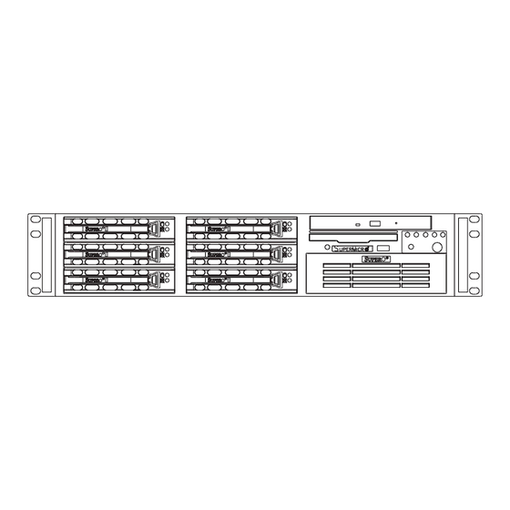
UPER ERVER 5026T-3F/5026T-T Manual Figure 6-1. Chassis: Front and Rear Views Floppy Drive CD-ROM Drive Control Panel SAS/SATA Drives (6) 5.25" Drive Bay System Reset Main Power Rear view Keyboard/Mouse Ports Dedicated IPMI LAN Port* 7 Low Profi le PCI Slots USB Ports COM1 Port VGA Port... -
Page 63: System Fans
Chapter 6: Advanced Chassis Setup System Fans Three 8-cm fans provide all the cooling needed for the SuperServer 5026T-3- F/5026T-T. It is very important that the chassis top cover is properly installed and making a good seal for the cooling air to circulate properly through the chassis and cool the components. -
Page 64: Drive Bay Installation/Removal
UPER ERVER 5026T-3F/5026T-T Manual Motherboard Power Supply System Cooling Fans Figure 6-2. System Cooling Fans Drive Bay Installation/Removal Accessing the Drive Bays SAS Drives: You do not need to access the inside of the chassis to replace or swap SAS drives. Proceed to the next step for instructions. CD-ROM/Floppy Disk Drive: For installing/removing the CD-ROM or fl... -
Page 65: Sas/Sata Drive Installation
Chapter 6: Advanced Chassis Setup SAS/SATA Drive Installation Mounting a SAS/SATA Drive in a Drive Carrier The SAS/SATA drives are mounted in drive carriers to simplify their installation and removal from the chassis. Since these carriers also help promote proper airfl ow for the SAS drive bays, even empty carriers without SAS drives installed must remain in the chassis. - Page 66 UPER ERVER 5026T-3F/5026T-T Manual Installing/Removing SAS/SATA Drives The SAS/SATA drive bays are located in the front of the chassis and are hot-swap units, meaning that they can be installed and removed while the system is run- ning. To remove a SAS/SATA drive, fi rst push the colored release button located beside the drive's LEDs.
-
Page 67: Installing Components In The 5.25" Drive Bays
Chapter 6: Advanced Chassis Setup Installing Components in the 5.25" Drive Bays The SC822TQ-400LPB chassis has two 5.25" drive bays. Components such as an extra fl oppy drive or CD-ROM drives can be installed into these 5.25" drive bays. Removing the Empty Drive Bay First power down the system. -
Page 68: Power Supply
UPER ERVER 5026T-3F/5026T-T Manual Power Supply The SuperServer 5026T-3F/5026T-T has a single 400 watt power supply. This power supply module has an auto-switching capability, which enables it to automatically sense and operate at a 100V to 220V input voltage. Power Supply Failure If the power supply fails, the system will shut down and you will need to replace the power supply unit. -
Page 69: Chapter 7 Bios
Chapter 7: BIOS Chapter 7 BIOS Introduction This chapter describes the AMI BIOS Setup Utility for the X8ST3-F/X8STE. The AMI ROM BIOS is stored in a Flash EEPROM and can be easily updated. This chapter describes the basic navigation of the AMI BIOS Setup Utility setup screens. Starting BIOS Setup Utility To enter the AMI BIOS Setup Utility screens, press the <Delete>... -
Page 70: Starting The Setup Utility
UPER ERVER 5026T-3F/5026T-T User's Manual Starting the Setup Utility Normally, the only visible Power-On Self-Test (POST) routine is the memory test. As the memory is being tested, press the <Delete> key to enter the main menu of the AMI BIOS Setup Utility. From the main menu, you can access the other setup screens. - Page 71 Chapter 7: BIOS Day MM/DD/YY format. The time is entered in HH:MM:SS format. (Note: The time is in the 24-hour format. For example, 5:30 P.M. appears as 17:30:00.) AMIBIOS Version Build Date Processor The AMI BIOS will automatically display the status of processor as shown below: Speed Physical Count Logical Count...
-
Page 72: Advanced Setup Confi Gurations
UPER ERVER 5026T-3F/5026T-T User's Manual Advanced Setup Confi gurations Use the arrow keys to select Boot Setup and hit <Enter> to access the submenu items: BOOT Feature Quick Boot If Enabled, this option will skip certain tests during POST to reduce the time needed for system boot. - Page 73 Chapter 7: BIOS Wait For 'F1' If Error This forces the system to wait until the 'F1' key is pressed if an error occurs. The options are Disabled and Enabled. Hit 'Del' Message Display This feature displays "Press DEL to run Setup" during POST. The options are Enabled and Disabled.
- Page 74 UPER ERVER 5026T-3F/5026T-T User's Manual is installed. For example, the default setting for the Intel® Core i7™ 965 is [24]. Press "+" or "-" on your keyboard to change this value. Clock Spread Spectrum Select Enable to use the feature of Clock Spectrum, which will allow the BIOS to monitor and attempt to reduce the level of Electromagnetic Interference caused by the components whenever needed.
- Page 75 Chapter 7: BIOS Intel® EIST Technology EIST (Enhanced Intel SpeedStep Technology) allows the system to automatically adjust processor voltage and core frequency in an effort to reduce power consump- tion and heat dissipation. Please refer to Intel’s web site for detailed information. The options are Disable: Disable GV3 and Enable: Enable GV3.
- Page 76 UPER ERVER 5026T-3F/5026T-T User's Manual Intel® C-STATE Architecture C-State, a processor power management architecture developed by Intel, can further reduce power consumption from the basic C1 (Halt State) state, which blocks clock cycles to the CPU. C-State is an idle state, and instructions are not processed by the CPU.
-
Page 77: Advanced Chipset Control
Chapter 7: BIOS card to handle some or all packet processing of this add-on card. For this moth- erboard, the TOE device is built inside the ESB 2 South Bridge chip. This feature is supported only by some types of processors (i.e., Intel Nehalem-WS 1S). The options are Enabled and Disabled. - Page 78 UPER ERVER 5026T-3F/5026T-T User's Manual Channel Mirror - The motherboard maintains two identical copies of all data in memory for redundancy. Lockstep - The motherboard uses two areas of memory to run the same set of operations in parallel. Sparing - A preset threshold of correctable errors is used to trigger fail-over. The spare memory is put online and used as active memory in place of the failed memory.
- Page 79 Chapter 7: BIOS Air Flow This item allows the user to set the desired speed of air fl ow to the DIMM mod- ules. Each increment is one mm/sec. The default is [1500]. Press "+" or "-" on your keyboard to change this value. Altitude This item allows the user to specify the altitude of the location where the com- puter is used.
- Page 80 UPER ERVER 5026T-3F/5026T-T User's Manual providing the user with greater reliability, security and availability in networking and data-sharing. The settings are Enabled and Disabled. Intel I/OAT The Intel I/OAT (I/O Acceleration Technology) signifi cantly reduces CPU overhead by leveraging CPU architectural improvements, freeing resources for more other tasks.
- Page 81 Chapter 7: BIOS IDE / Floppy Confi guration When this submenu is selected, the AMI BIOS automatically detects the presence of the IDE Devices and displays the following items: Floppy A This feature allows the user to select the type of fl oppy drive connected to the sys- tem.
- Page 82 UPER ERVER 5026T-3F/5026T-T User's Manual Primary IDE Master/Slave, Secondary IDE Master/Slave, Third IDE Master, and Fourth IDE Master These settings allow the user to set the parameters of Primary IDE Master/Slave, Secondary IDE Master/Slave, Third and Fourth IDE Master slots. Hit <Enter> to activate the following submenu screen for detailed options of these items.
- Page 83 Chapter 7: BIOS Select 4 to allow the AMI BIOS to use PIO mode 4. It has a data transfer band- width of 32-Bits. Select Enabled to enable 32-Bit data transfer. DMA Mode Select Auto to allow the BIOS to automatically detect IDE DMA mode when the IDE disk drive support cannot be determined.
- Page 84 UPER ERVER 5026T-3F/5026T-T User's Manual 32Bit Data Transfer Select Enable to enable the function of 32-bit IDE data transfer. The options are Enabled and Disabled. PCI/PnP Confi guration This feature allows the user to set the PCI/PnP confi gurations for the following items: Clear NVRAM This feature clears the NVRAM during system boot.
- Page 85 Chapter 7: BIOS Super IO Device Confi guration Serial Port1 Address/ Serial Port2 Address This option specifi es the base I/O port address and the Interrupt Request address of Serial Port 1 and Serial Port 2. Select Disabled to prevent the serial port from accessing any system resources.
- Page 86 UPER ERVER 5026T-3F/5026T-T User's Manual Redirection After BIOS POST Select Disabled to turn off Console Redirection after Power-On Self-Test (POST). Select Always to keep Console Redirection active all the time after POST. (Note: This setting may not be supported by some operating systems.) Select Boot Loader to keep Console Redirection active during POST and Boot Loader.
- Page 87 Chapter 7: BIOS manufacturer to give the CPU and system fans additional time needed for CPU and system cooling. Fan Speed Control Modes This feature allows the user to decide how the system controls the speeds of the onboard fans. The CPU temperature and the fan speed are correlative. When the CPU on-die temperature increases, the fan speed will also increase, and vice versa.
- Page 88 UPER ERVER 5026T-3F/5026T-T User's Manual ACPI Version Features The options are ACPI v1.0, ACPI v2.0 and ACPI v3.0. Please refer to ACPI's website for further explanation: http://www.acpi.info/ IPMI Confi guration (X8ST3-F Only) Intelligent Platform Management Interface (IPMI) is a set of common interfaces that IT administrators can use to monitor system health and to manage the system as a whole.
- Page 89 Chapter 7: BIOS MAC Address - The BIOS will automatically enter the MAC address of this machine, however it may be over-ridden. MAC addresses are 6 two-digit hexa- decimal numbers (Base 16, 0 ~ 9, A, B, C, D, E, F) separated by dots. (i.e., 00.30.48.D0.D4.60) Subnet Mask - Subnet masks tell the network which subnet this machine be- longs to.
- Page 90 UPER ERVER 5026T-3F/5026T-T User's Manual BMC WatchDog TimeOut [Min:Sec] This option appears if BMC Watch Dog Timer Action (above) is enabled. This is a timed delay in minutes or seconds, before a system power down or reset after an operating system failure is detected. The options are [5 Min], [1 Min], [30 Sec], and [10 Sec].
-
Page 91: Security Settings
Chapter 7: BIOS Security Settings The AMI BIOS provides a Supervisor and a User password. If you use both pass- words, the Supervisor password must be set fi rst. Supervisor Password This item indicates if a supervisor password has been entered for the system. Clear means such a password has not been used and Set means a supervisor password has been entered for the system. -
Page 92: Boot Confi Guration
UPER ERVER 5026T-3F/5026T-T User's Manual Clear User Password (Available only if User Password has been set) Password Check Available options are Setup and Always. Boot Sector Virus Protection When Enabled, the AMI BOIS displays a warning when any program (or virus) is- sues a Disk Format command or attempts to write to the boot sector of the hard disk drive. -
Page 93: Exit Options
Chapter 7: BIOS Removable Drives This feature allows the user to specify the boot sequence from available Removable Drives. The settings are 1st boot device, 2nd boot device, and Disabled. • 1st Drive • 2nd boot device - [USB: XXXXXXXXX] CD/DVD Drives This feature allows the user to specify the boot sequence from available CD/DVD Drives. - Page 94 UPER ERVER 5026T-3F/5026T-T User's Manual Discard Changes and Exit Select this option to quit the BIOS Setup without making any permanent changes to the system confi guration, and reboot the computer. Select Discard Changes and Exit from the Exit menu and press <Enter>. Discard Changes Select this option and press <Enter>...
-
Page 95: Appendix A Post Error Beep Codes
Appendix A: POST Error Beep Codes Appendix A POST Error Beep Codes This section lists POST (Power On Self Test) error beep codes for the Phoenix BIOS. POST error beep codes are divided into two categories: recoverable and terminal. This section lists Beep Codes for recoverable POST errors. Recoverable POST Error Beep Codes When a recoverable type of error occurs during POST, BIOS will display a POST code that describes the problem. - Page 96 UPER ERVER 5026T-3F/5026T-T User's Manual Notes...
-
Page 97: Appendix B System Specifi Cations
Appendix B: System Specifi cations Appendix B System Specifi cations Processors Single Intel Core i7 and future Intel® Nehalem processor families (next generation Intel Xeon® processor) Note: Please refer to the motherboard specifi cations pages on our web site for updates on supported processors. - Page 98 UPER ERVER 5026T-3F/5026T-T User's Manual Expansion Slots Three PCI-Express 2.0 x8 slot, one PCI-Express x4 slot, two 32-bit PCI slots and one IPMI slot Motherboard (5026T-3F/5026T-T) Model: X8ST3-F/X8STE Form Factor: ATX Dimensions: 12 x 10 in (305 x 254 mm) System Input Requirements AC Input Voltage: 100-240V AC Rated Input Current: 6A (115V) to 2.7A (230V)
- Page 99 Appendix B: System Specifi cations Electromagnetic Immunity: EN 55024/CISPR 24, (EN 61000-4-2, EN 61000-4-3, EN 61000-4-4, EN 61000-4-5, EN 61000-4-6, EN 61000-4-8, EN 61000-4-11) Safety: EN 60950/IEC 60950-Compliant, UL Listed (USA), CUL Listed (Canada), TUV Certifi ed (Germany), CE Marking (Europe) California Best Management Practices Regulations for Perchlorate Materials: This Perchlorate warning applies only to products containing CR (Manganese Dioxide) Lithium coin cells.
- Page 100 UPER ERVER 5026T-3F/5026T-T User's Manual (continued from front) The products sold by Supermicro are not intended for and will not be used in life support systems, medical equipment, nuclear facilities or systems, aircraft, aircraft devices, aircraft/emergency com- munication devices or other critical systems whose failure to perform be reasonably expected to result in signifi...
Need help?
Do you have a question about the SUPERSERVER 5026T-3F and is the answer not in the manual?
Questions and answers