Table of Contents
Advertisement
Quick Links
Advertisement
Table of Contents

Related Manuals for Supero 2U Twin2 SuperServer 5026Ti-HTRF


Summary of Contents for Supero 2U Twin2 SuperServer 5026Ti-HTRF
- Page 1 ® UPER 2U Twin SuperServer 5026Ti-HTRF USER’S MANUAL Revision 1.0a...
- Page 2 The information in this User’s Manual has been carefully reviewed and is believed to be accurate. The vendor assumes no responsibility for any inaccuracies that may be contained in this document, makes no commitment to update or to keep current the information in this manual, or to notify any person or organization of the updates.
- Page 3 Preface Preface About This Manual This manual is written for professional system integrators and PC technicians. It provides information for the installation and use of the SuperServer 5026Ti-HTRF. Installation and maintenance should be performed by experienced technicians only. The SuperServer 5026Ti-HTRF is a 2U Twin (two serverboards/nodes in a 2U chassis) rackmount server based on the SC827H-R920B server chassis and four Super X8SiT-HF serverboards.
- Page 4 SUPERSERVER 5026Ti-HTRF User's Manual when adding or removing processors or main memory and when reconfi guring the serverboard. Chapter 6: Advanced Chassis Setup Refer to Chapter 6 for detailed information on the SC827H-R920B 2U rackmount server chassis. You should follow the procedures given in this chapter when install- ing, removing or reconfi...
- Page 5 Preface Notes...
-
Page 6: Table Of Contents
SUPERSERVER 5026Ti-HTRF User's Manual Table of Contents Chapter 1 Introduction Overview ......................1-1 Motherboard Features ..................1-2 Processor ......................1-2 Memory ......................1-2 Onboard SATA ....................1-2 PCI Expansion Slots ..................1-2 Onboard Controllers/Ports ................1-2 Server Chassis Features ................1-4 System Power .................... - Page 7 Table of Contents Checking the Serverboard Setup ..............2-9 Preparing to Power On ................. 2-10 Chapter 3 System Interface Overview ......................3-1 Control Panel Buttons ..................3-1 Power ......................3-1 UID ........................3-1 Control Panel LEDs ..................3-2 Overheat/Fan Fail ................... 3-2 NIC ........................
- Page 8 5-11 Onboard Indicators ..................5-26 5-12 SATA Ports ....................5-27 5-13 Installing Software ..................5-28 Supero Doctor III ................... 5-29 Chapter 6 Advanced Chassis Setup Static-Sensitive Devices .................. 6-1 Precautions ..................... 6-1 Unpacking ....................... 6-1 Control Panel ....................6-2 System Fans ....................6-2 Fan Confi...
-
Page 9: Chapter 1 Introduction
Chapter 1: Introduction Chapter 1 Introduction Overview The Supermicro SuperServer 5026Ti-HTRF is "2U Twin " server composed of the SC827H-R920B chassis and four X8SiT-HF motherboards. Please refer to our web site for information on operating systems that have been certifi ed for use with the 5026Ti-HTRF. -
Page 10: Motherboard Features
UPER ERVER 5026Ti-HTRF User's Manual Motherboard Features At the heart of the SuperServer 5026Ti-HTRF are four X8SiT-HF single processor motherboards based upon Intel's 3420 chipset. Below are the main features of the X8SiT-HF. Note that the features on each board are quadrupled for the server, which includes four nodes. - Page 11 Chapter 1: Introduction DIMM1(Far) DDR3 (CHA) PCIe2.0_x16 DIMM2 PCI-E x16 SLOT 5.0Gb/s Xeon 3400 Series 1333/1066MHz DIMM3 6 UDIMM DDR3 (CHB) DIMM1(Far) VID[0-7] DIMM2 1333/1066MHz DIMM3 VRM 11.1 MISC VRs SATA-II PCIe_x1 GLAN1 RJ45 6 SATA PORTS 2.5Gbps 82576BE 300MB/s USB2.0 PCIe_x1 GLAN2...
-
Page 12: Server Chassis Features
UPER ERVER 5026Ti-HTRF User's Manual Server Chassis Features The following is a general outline of the main features of the SC827H-R920B 2U chassis. Details on the chassis can be found in Chapter 6. System Power When confi gured as a SuperServer 5026Ti-HTRF, the SC827H-R920B includes a redundant (dual) 920W power supply, which provides power to all four serverboards (nodes). -
Page 13: Twin 2 : System Notes
Chapter 1: Introduction 2U Twin : System Notes As a 2U Twin confi guration, the 5026Ti-HTRF is a unique server system. With four system boards incorporated into a single chassis acting as four separate nodes, there are several points you should keep in mind. Nodes Each of the serverboards act as a separate node in the system. -
Page 14: Contacting Supermicro
UPER ERVER 5026Ti-HTRF User's Manual Contacting Supermicro Headquarters Address: Super Micro Computer, Inc. 980 Rock Ave. San Jose, CA 95131 U.S.A. Tel: +1 (408) 503-8000 Fax: +1 (408) 503-8008 Email: marketing@supermicro.com (General Information) support@supermicro.com (Technical Support) Web Site: www.supermicro.com Europe Address: Super Micro Computer B.V. -
Page 15: Chapter 2 Server Installation
Chapter 2: Server Installation Chapter 2 Server Installation Overview This chapter provides a quick setup checklist to get the 5026Ti-HTRF up and running. Following these steps in the order given should enable you to have the system operational within a minimum amount of time. This quick setup assumes that your system has come to you with the processors and memory preinstalled. -
Page 16: Choosing A Setup Location
SUPERSERVER 5026Ti-HTRF User's Manual Choosing a Setup Location • Leave enough clearance in front of the rack to enable you to open the front door completely (~25 inches). • Leave approximately 30 inches of clearance in the back of the rack to allow for suffi... -
Page 17: Rack Mounting Considerations
Chapter 2: Server Installation • Allow the hot plug SATA drives and power supply modules to cool before touch- ing them. • Always keep the rack's front door and all panels and components on the servers closed when not servicing to maintain proper cooling. •... -
Page 18: Removing The Protective Film
SUPERSERVER 5026Ti-HTRF User's Manual Removing the Protective Film Before operating the server for the fi rst time, it is important to remove the protec- tive fi lm covering the top of the chassis, in order to allow for proper ventilation and cooling. -
Page 19: Rack Mounting Instructions
Chapter 2: Server Installation Rack Mounting Instructions This section provides information on installing the SC827 chassis into a rack unit with the quick-release rails provided. There are a variety of rack units on the market, which may mean the assembly procedure will differ slightly. You should also refer to the installation instructions that came with the rack unit you are using. -
Page 20: Installing The Inner Rail Extensions
SUPERSERVER 5026Ti-HTRF User's Manual Installing the Inner Rail Extensions The SC827 chassis includes a set of inner rails in two sections: inner rails and inner rail extensions. The inner rails are pre-attached to the chassis, and do not interfere with normal use of the chassis if you decide not to use a server rack. The inner rail extension is attached to the inner rail to mount the chassis in the rack. -
Page 21: Outer Rack Rails
Chapter 2: Server Installation Figure 2-4: Assembling the Outer Rails Outer Rack Rails Outer rails attach to the rack and hold the chassis in place. The outer rails for the SC827 chassis extend between 30 inches and 33 inches. Installing the Outer Rails to the Rack Secure the back end of the outer rail to the rack, using the screws provided. - Page 22 SUPERSERVER 5026Ti-HTRF User's Manual Figure 2-5: Installing Into the Rack Installing the Chassis into a Rack Extend the outer rails as illustrated above. Align the inner rails of the chassis with the outer rails on the rack. Slide the inner rails into the outer rails, keeping the pressure even on both sides.
-
Page 23: Checking The Serverboard Setup
Chapter 2: Server Installation Checking the Serverboard Setup After you install the system in the rack, you will need to access the inside of the nodes to make sure the serverboard is properly installed. Accessing the Inside of a Node (Figure 2-6) Before removing a node, unplug all the cables that connect to that node. -
Page 24: Preparing To Power On
SUPERSERVER 5026Ti-HTRF User's Manual Preparing to Power On Next, you should check to make sure the SATA drives and the backplane have been properly installed and all connections have been made. Checking the SATA drives The SATA disk drives are accessable from the front of the server and can be installed and removed from the front of the chassis without removing the top chassis cover. - Page 25 Chapter 2: Server Installation Figure 2-6. Removing a Node from the System 2-11...
- Page 26 SUPERSERVER 5026Ti-HTRF User's Manual Notes 2-12...
-
Page 27: Chapter 3 System Interface
Chapter 3: System Interface Chapter 3 System Interface Overview There are LEDs on the control panels and on the SATA drive carriers to keep you constantly informed of the overall status of the system as well as the activity and health of specifi... -
Page 28: Control Panel Leds
SUPERSERVER 5026Ti-HTRF User's Manual Control Panel LEDs In addition to the LEDs built into the power and UID buttons, each of the four control panels located on the front of the SC827H-R920B chassis has two LEDs that provide you with critical information related their own node. This section explains what each LED indicates when illuminated and any corrective action you may need to take. -
Page 29: Chapter 4 System Safety
Chapter 4: System Safety Chapter 4 System Safety Electrical Safety Precautions Basic electrical safety precautions should be followed to protect yourself from harm and the SuperServer 5026Ti-HTRF from damage: • Be aware of the locations of the power on/off switch on the chassis as well as the room's emergency power-off switch, disconnection switch or electrical outlet. -
Page 30: General Safety Precautions
SUPERSERVER 5026Ti-HTRF User's Manual • This product may be connected to an IT power system. In all cases, make sure that the unit is also reliably connected to Earth (ground). • Serverboard Battery: CAUTION - There is a danger of explosion if the onboard battery is installed upside down, which will reverse its polarites (see Figure 4-1). -
Page 31: Esd Precautions
Chapter 4: System Safety • Remove any jewelry or metal objects from your body, which are excellent metal conductors that can create short circuits and harm you if they come into contact with printed circuit boards or areas where power is present. •... -
Page 32: Operating Precautions
SUPERSERVER 5026Ti-HTRF User's Manual Operating Precautions Care must be taken to assure that the chassis cover is in place when the 5026Ti- HTRF is operating to assure proper cooling. Out of warranty damage to the system can occur if this practice is not strictly followed. Figure 4-1. -
Page 33: Chapter 5 Advanced Motherboard Setup
Chapter 5: Advanced Motherboard Setup Chapter 5 Advanced Motherboard Setup This chapter covers the steps required to install the X8SiT-HF motherboard into the chassis, connect the data and power cables and install add-on cards. All mother- board jumpers and connections are also described. A layout and quick reference chart are included in this chapter for your reference. -
Page 34: Unpacking
SUPERSERVER 5026Ti-HTRF User's Manual Unpacking The motherboard is shipped in antistatic packaging to avoid electrical static dis- charge. When unpacking the board, make sure the person handling it is static protected. Motherboard Installation This section explains the fi rst step of physically mounting the X8SiT-HF into the SC827H-R920B chassis. -
Page 35: Connecting Cables
Chapter 5: Advanced Motherboard Setup Connecting Cables Now that the motherboard is installed, the next step is to connect the cables to the board. These include the data cables for the peripherals and control panel and the power cables. Connecting Data Cables The cables used to transfer data from the peripheral devices have been carefully routed to prevent them from blocking the fl... -
Page 36: Rear I/O Ports
SUPERSERVER 5026Ti-HTRF User's Manual Figure 5-1. Control Panel Header Pins Power Button Ground Reset Button Ground LED_Anode+ PWR Fail OH/Fan Fail UID LED NIC2 LED LED_Anode+ NIC1 LED LED_Anode+ HDD LED LED_Anode+ Power LED LED_Anode+ Rear I/O Ports The rear I/O ports are color coded in conformance with the PC 99 specifi cation. See Figure 5-2 below for the colors and locations of the various I/O ports. -
Page 37: Processor And Heatsink Installation
Chapter 5: Advanced Motherboard Setup Processor and Heatsink Installation When handling the processor package, avoid placing direct pressure on the label area of the fan. Notes: • Always connect the power cord last and always remove it before adding, re- moving or changing any hardware components. - Page 38 SUPERSERVER 5026Ti-HTRF User's Manual Gently lift the load lever to open the load plate. Remove the plate cap. Use your thumb and your index fi nger to hold the CPU at the top center edge and the bottom center edge of the CPU. Align the CPU key that is the semi-circle cutouts against the socket keys.
-
Page 39: Installing A Passive Cpu Heatsink
Chapter 5: Advanced Motherboard Setup Use your thumb to gently push the load lever down to the lever lock. Save the plastic PnP cap. The motherboard must be shipped with the PnP cap properly installed to protect the CPU socket pins. Shipment without the PnP cap properly installed will cause damage to the socket pins. - Page 40 SUPERSERVER 5026Ti-HTRF User's Manual Figure 5-3. Installing the Heatsink Removing the Heatsink Warning: We do not recommend removing the CPU or the heatsink. How- ever, if you do need to remove the heatsink, please follow the instructions below to prevent damage to the CPU or other components. Unscrew the heatsink screws from the motherboard in the sequence as shown in the illustration below.
-
Page 41: Installing Memory
Chapter 5: Advanced Motherboard Setup Figure 5-4. Removing the Heatsink Screw #4 Loosen screws in the sequence shown Screw #1 Screw #2 Motherboard Screw #3 Installing Memory Note: Check the Supermicro web site for recommended memory modules. CAUTION Exercise extreme care when installing or removing DIMM modules to prevent any possible damage. -
Page 42: Memory Support
SUPERSERVER 5026Ti-HTRF User's Manual Memory Support The X8SiT-HF supports up to 16GB of DDR3 ECC UDIMM or up to 32GB of ECC DDR3 RDIMM (1333/1066/800 MHz in 6 DIMM slots.) Populating the slots with a pair of memory modules of the same type and size will result in interleaved mem- ory, which will improve memory performance. -
Page 43: Memory Population Guidelines
Chapter 5: Advanced Motherboard Setup DDR3 1066/1333 UDIMM/RDIMM requires Slot 3, Channel A Slot 2, Channel A Slot 1, Channel A (Blue) Slot 3, Channel B Slot 2, Channel B Slot 1, Channel B (Blue) Figure A (rotated -90 degrees) Memory Population Guidelines Please follow the tables below when populating the X8SiT-HF. - Page 44 SUPERSERVER 5026Ti-HTRF User's Manual Figure 5-3. DIMM Installation Position the DIMM module's bottom key so it aligns with the receptive point on the slot. Notches Push the Lock/Re- lease tabs to their Release Release positions. Make sure that the DIMM module's side notches align with the slot's Lock/Release Release...
- Page 45 Chapter 5: Advanced Motherboard Setup Note: Due to memory allocation to system devices, the amount of memory that remains available for operational use will be reduced when 4 GB of RAM is used. The reduction in memory availability is disproportional. For Microsoft Windows users: Microsoft implemented a design change in Win- dows XP with Service Pack 2 (SP2) and Windows Vista.
-
Page 46: Adding Pci Expansion Cards
SUPERSERVER 5026Ti-HTRF User's Manual Adding PCI Expansion Cards The 5026Ti-HTRF includes four preinstalled riser cards designed specifi cally for use in the SC827 rackmount chassis. These riser cards support low-profi le PCI Express x16 cards to fi t inside the chassis. Installing an Expansion Card After powering down the system, remove the PCI slot shield. - Page 47 Chapter 5: Advanced Motherboard Setup Figure 5-4. X8SiT-HF Layout COM1 JPL1 JPL2 JPG1 JPUSB1 JWOR1:Wake on Ring JPUSB1:B/P USB WAKE UP 1-2:ENABLE 2-3:DISABLE JPL1:LAN1 1-2:ENABLE 2-3:DISABLE JPL2:LAN2 1-2:ENABLE 2-3:DISABLE JI2C1/JI2C2 ON:Enable OFF:Disable :CHASSIS INTRUSION JBT1:CMOS CLEAR JBT1 JPT1:TPM 1-2:Enable 2-3:Disable JTPM JWF1 X8SIT-F...
- Page 48 SUPERSERVER 5026Ti-HTRF User's Manual Connectors/Headers Number Connector Description Unit ID Switch SMB Header for IPMI 2.0 Slot 1 PCI-E x16 2.0 Slot (Slot 1) SATA0~5 SATA Ports 0 through 5 T-SGPIO-0/1 Serial General Purpose I/O Headers (for SATA) JWF1 Compact Flash/DOM Power Connector DIMMs 1~6 Memory Slots (DDR3 1066/1333 UDIMM/RDIMM) 4-Pin Auxilliary Power for Peripheral Devices...
-
Page 49: Connector Defi Nitions
Chapter 5: Advanced Motherboard Setup Connector Defi nitions 20-pin Main Power Connector Pin Defi nitions 20-pin Proprietary Power Pin# Defi nition Pin# Defi nition Connectors PS On Ground 5VSB Ground There are two 20-pin main power sup- ply connectors (JWR3, JWR4) and a Ground Ground 4-pin auxiliary power connector (JP3) - Page 50 SUPERSERVER 5026Ti-HTRF User's Manual Reset Button Reset Button Pin Defi nitions (JF1) The reset button (from the computer Pin# Defi nition chassis) connects to pins 3 and 4 of Reset JF1. See the table on the right for pin Ground defi...
- Page 51 Chapter 5: Advanced Motherboard Setup Power LED The Power LED connector is located Power LED Pin Defi nitions (JF1) on pins 15 and 16 of JF1. This con- Pin# Defi nition nection is used to provide LED indica- tion of power being supplied to the Ground system.
- Page 52 SUPERSERVER 5026Ti-HTRF User's Manual Unit ID Switch There are three Unit Identifi cation (UID) devices on the motherboard. A rear UID switch and a rear UID LED indicator. The front panel UID UID Switch LED is connected to a pin in the Pin# Defi...
- Page 53 Chapter 5: Advanced Motherboard Setup Power Supply I C Connector PWR Supply I Pin Defi nitions The power supply (I C) connector is Pin# Defi nition located at JPI C on the motherboard. Clock This connector can be used to monitor Data the status of the power supply, fan and system temperature.
- Page 54 SUPERSERVER 5026Ti-HTRF User's Manual Trusted Platform Module Header Pin Defi nitions Trusted Platform Module Header Pin # Defi nition Pin # Defi nition LCLK This header is used to connect a LFRAME No Pin Trusted Platform Module (TPM), LRESET VCC5 available separately from a third-party LAD3 LAD2...
-
Page 55: 5-10 Jumper Settings
Chapter 5: Advanced Motherboard Setup 5-10 Jumper Settings Explanation of Jumpers To modify the operation of the mother- board, jumpers can be used to choose Connector between optional settings. Jumpers Pins create shorts between two pins to change the function of the connector. Pin 1 is identifi... - Page 56 SUPERSERVER 5026Ti-HTRF User's Manual SMB Bus to PCI Slots Use jumpers JI C1 and JI C2 to en- C to PCI-Slots Jumper Settings able PCI Slot SMB (System Manage- Jumper Defi nition ment Bus) support to improve system Closed Enabled management for the PCI slots.
- Page 57 Chapter 5: Advanced Motherboard Setup VGA Enable VGA Enable/Disable JPG1 allows you to enable or disable Jumper Settings the onboard VGA connector. The Both Jumpers Defi nition default position is on pins 1 and 2 Pins 1-2 Enabled (Default) to enable VGA. See the table on the Pins 2-3 Disabled right for jumper settings.
-
Page 58: 5-11 Onboard Indicators
SUPERSERVER 5026Ti-HTRF User's Manual 5-11 Onboard Indicators LAN1/2 LEDs The Ethernet ports (located beside the LAN1/2 LED (Connection Speed Indicator) VGA port) have two LEDs. On each LED Color Defi nition port, the yellow LED indicates activity No Connection or 10 Mb/s while the other LED may be green, Green 100 Mb/s... -
Page 59: 5-12 Sata Ports
Chapter 5: Advanced Motherboard Setup Rear UID LED The rear UID LED is located at LE5 on the backplane. This LED is used in conjunction with the front UID LED and the rear UID switch to provide easy identifi cation of a system that might be in need of service. -
Page 60: 5-13 Installing Software
SUPERSERVER 5026Ti-HTRF User's Manual 5-13 Installing Software After the hardware has been installed, you should fi rst install the operating system and then the drivers. The necessary drivers are all included on the Supermicro CDs that came packaged with your motherboard. Driver/Tool Installation Display Screen Note: Click the icons showing a hand writing on paper to view the readme fi... -
Page 61: Supero Doctor Iii
The Supero Doctor III program is a web-based management tool that supports remote management capability. It includes Remote and Local Management tools. The local management is called SD III Client. The Supero Doctor III program in- cluded on the CD-ROM that came with your motherboard allows you to monitor the environment and operations of your system. - Page 62 Supero Doctor III Interface Display Screen (Remote Control) Note: SD III Software Revision 1.0 can be downloaded from our Web Site at: ftp://ftp. supermicro.com/utility/Supero_Doctor_III/. You can also download the SDIII User's Guide at: <http://www.supermicro.com/PRODUCT/Manuals/SDIII/UserGuide.pdf>. For Linux, we will recommend using Supero Doctor II. 5-30...
-
Page 63: Chapter 6 Advanced Chassis Setup
Chapter 6: Advanced Chassis Setup Chapter 6 Advanced Chassis Setup This chapter covers the steps required to install components and perform mainte- nance on the SC827H-R920B chassis. For component installation, follow the steps in the order given to eliminate the most common problems encountered. If some steps are unnecessary, skip ahead to the step that follows. -
Page 64: Control Panel
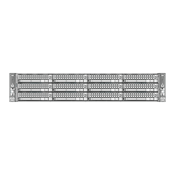
SUPERSERVER 5026Ti-HTRF User's Manual Figure 6-1. Chassis Front View Node B Control Panel Node D Control Panel SATA Drives Node A Control Panel Node C Control Panel Figure 6-2. Chassis Rear View Dedicated IPMI LAN Port Dedicated IPMI LAN Port PCI-Express x16 Slot Power Supply LAN Ports... -
Page 65: Fan Confi Guration
Chapter 6: Advanced Chassis Setup Fan Confi guration In the 2U Twin , each node (serverboard) controls the two fans that reside on its side of the chassis. If the fan speed settings in BIOS are set to different values for each two node, the BIOS setting with the higher fan speed will apply to both. -
Page 66: Hard Drive Installation/Removal
SUPERSERVER 5026Ti-HTRF User's Manual Hard Drive Installation/Removal Overview The hard drives are mounted in drive carriers to simplify their installation and removal from the chassis. These carriers also help promote proper airfl ow for the system. For this reason, even empty carriers without drives installed must remain in the chassis. - Page 67 Chapter 6: Advanced Chassis Setup Figure 6-3. Removing a Dummy Drive Tray Figure 6-4. Mounting a Hard Drive in a Carrier Hard Drive Drive Carrier Installing/Removing Hot-swap Drives To remove a carrier, push the release button located beside the drive LEDs. Swing the handle fully out and use it to pull the unit straight out (see Figure 6-5).
- Page 68 SUPERSERVER 5026Ti-HTRF User's Manual Figure 6-5. Removing a Hard Drive Figure 6-6. Drives and Nodes: Logical Confi guration Note: see Figure 6-1 for the locations of the control panels that are associated with each node.
-
Page 69: Node Installation/Removal
Chapter 6: Advanced Chassis Setup Node Installation/Removal As with any server system, power must be removed from the serverboard when upgrading or installing memory or processors. In the 2U Twin server, the server- boards (nodes) are capable of being hot-swapped from the chassis, allowing one to be powered down for servicing while the other continues operating. - Page 70 SUPERSERVER 5026Ti-HTRF User's Manual Figure 6-7. Removing a System Node...
-
Page 71: Installing The Air Shrouds
Chapter 6: Advanced Chassis Setup Installing the Air Shrouds Air Shrouds Air shrouds concentrate airfl ow to maximize fan effi ciency. The SC827 chassis air shroud does not require screws to set up. Two identical air shrouds are required, one for each serverboard/node. Installing an Air Shroud Confi... - Page 72 SUPERSERVER 5026Ti-HTRF User's Manual Figure 6-8. Removing the Power Supply Release Tab 6-10...
-
Page 73: Chapter 7 Bios
Chapter 7: BIOS Chapter 7 BIOS Introduction This chapter describes the AMI BIOS Setup Utility for the X8SiT-HF. The AMI ROM BIOS is stored in a Flash EEPROM and can be easily updated. This chapter de- scribes the basic navigation of the AMI BIOS Setup Utility setup screens. Note: For instructions on BIOS recovery, please refer to the instruction guide posted at http://www.supermicro.com/support/manuals/. -
Page 74: How To Start The Setup Utility
UPER ERVER 5026Ti-HTRF User's Manual How to Start the Setup Utility Normally, the only visible Power-On Self-Test (POST) routine is the memory test. As the memory is being tested, press the <Delete> key to enter the main menu of the AMI BIOS Setup Utility. From the main menu, you can access the other setup screens. - Page 75 Chapter 7: BIOS System Overview: The following BIOS information will be displayed: System Time/System Date Use this option to change the system time and date. Highlight System Time or Sys- tem Date using the arrow keys. Enter new values through the keyboard. Press the <Tab>...
-
Page 76: Advanced Setup Confi Gurations
UPER ERVER 5026Ti-HTRF User's Manual Advanced Setup Confi gurations Use the arrow keys to select Boot Setup and hit <Enter> to access the submenu items: BOOT Feature Quick Boot If Enabled, this option will skip certain tests during POST to reduce the time needed for system boot. - Page 77 Chapter 7: BIOS Hit 'Del' Message Display This feature displays "Press DEL to run Setup" during POST. The options are Enabled and Disabled. Watch Dog Function If enabled, the Watch Dog Timer will allow the system to reboot when it is inactive for more than 5 minutes.
- Page 78 UPER ERVER 5026Ti-HTRF User's Manual Processor & Clock Options Warning : Take Caution when changing the Advanced settings. An incorrect value, a very high DRAM frequency or incorrect DRAM timing may cause system to become unstable. When this occurs, revert to the default setting. CPU Ratio This feature allows the user to use the CPU clock multiplier to multiply CPU speed in order to enhance performance.
- Page 79 Chapter 7: BIOS Execute-Disable Bit Capability (Available when supported by the OS and the CPU) Set to Enabled to enable the Execute Disable Bit which will allow the processor to designate areas in the system memory where an application code can execute and where it cannot, thus preventing a worm or a virus from fl...
- Page 80 UPER ERVER 5026Ti-HTRF User's Manual C3 Auto Demotion When enabled, the CPU will conditionally demote C6 or C7 requests to C3 based on un-core auto-demote information. The options are Disabled and Enabled. Advanced Chipset Control The items included in the Advanced Settings submenu are listed below. Memory Remap Feature This feature, when enabled, allows the remapping of everlapped PCI memory above the total physical memory.
- Page 81 Chapter 7: BIOS Confi gure SATA as This feature allows the user to select the drive type for SATA#1. The options are IDE, RAID and AHCI. PCH RAID CodeBase (Available if RAID is selected above) Select Intel to enable the Intel SATA Host RAID Utility. Select Adaptec to use the Adaptec Host RAID Utility.
- Page 82 UPER ERVER 5026Ti-HTRF User's Manual PIO Mode The IDE PIO (Programmable I/O) Mode programs timing cycles between the IDE drive and the programmable IDE controller. As the PIO mode increases, the cycle time decreases. The options are Auto, 0, 1, 2, 3, and 4. Select Auto to allow the AMI BIOS to automatically detect the PIO mode.
- Page 83 Chapter 7: BIOS Select UDMA2 to allow the BIOS to use Ultra DMA mode 2. It has a data transfer rate of 33.3 MBs. Select UDMA3 to allow the BIOS to use Ultra DMA mode 3. It has a data transfer rate of 66.6 MBs.
- Page 84 UPER ERVER 5026Ti-HTRF User's Manual PCIE I/O Performace This feature selects the setting for the processor's PCIE maximum payload size. The options are 128B and 256B. ROM Scan Ordering This item determines what kind of option ROM activates over another. The options are Onboard First and Add-on First.
- Page 85 Chapter 7: BIOS Serial Port Number This feature allows the user to decide which serial port to be used for Console Redirection. The options are COM 1 and COM 3. Note: Serial Over LAN (SOL) will be enabled when either COM 1 or COM 3 is selected.
- Page 86 UPER ERVER 5026Ti-HTRF User's Manual Warning: Any temperature that exceeds the CPU threshold temperature predefi ned by the CPU manufacturer may result in CPU overheat or system instability. When the CPU temperature reaches this predefi ned threshold, the CPU and system cooling fans will run at full speed. The options are: •...
- Page 87 Chapter 7: BIOS even with the CPU fan running at full speed, the system buzzer will activate and the Overheat LED will turn on. The Early Alarm – the Overheat LED and system buzzer will be activated exactly when the High level is reached. The CPU fan will run at full speed to bring the CPU temperature down.
- Page 88 UPER ERVER 5026Ti-HTRF User's Manual better system cooling. The Performance setting is recommended for high-power- consuming and high-density systems. Select Balanced for the onboard fans to run at 50% of the Initial PWM Cycle in order to balance the needs between system cooling and power saving.
- Page 89 Chapter 7: BIOS ACPI Version Features The options are ACPI v1.0, ACPI v2.0 and ACPI v3.0. Please refer to ACPI's website for further explanation: http://www.acpi.info/ IPMI Confi guration Intelligent Platform Management Interface (IPMI) is a set of common interfaces that IT administrators can use to monitor system health and to manage the system as a whole.
- Page 90 UPER ERVER 5026Ti-HTRF User's Manual Address must be manually entered below. If DHCP is selected, the next three items will be confi gured automatically and will be grayed out. The options are Static and DHCP. IP Address - Enter the IP address for this machine. This should be in decimal and in dotted quad form (i.e., 192.168.10.253).
- Page 91 Chapter 7: BIOS PCIE Error Log Use this option to enable logging of errors encountered in the system's PCIe bus. The options are Yes and No. 7-19...
-
Page 92: Security Settings
UPER ERVER 5026Ti-HTRF User's Manual Security Settings The AMI BIOS provides a Supervisor and a User password. If you use both pass- words, the Supervisor password must be set fi rst. Supervisor Password This item indicates if a supervisor password has been entered for the system. Clear means such a password has not been used and Set means a supervisor password has been entered for the system. -
Page 93: Boot Settings
Chapter 7: BIOS Clear User Password (Available only if User Password has been set) Password Check Available options are Setup and Always. Boot Sector Virus Protection When Enabled, the AMI BOIS displays a warning when any program (or virus) is- sues a Disk Format command or attempts to write to the boot sector of the hard disk drive. -
Page 94: Exit Options
UPER ERVER 5026Ti-HTRF User's Manual Hard Disk Drives This feature allows the user to specify the sequence of priority from the available Hard Drives. • 1st Drive [SATA: XXXXXXXXXX] • 2nd Drive [SATA: XXXXXXXXXX] Removable Drives This feature allows the user to specify the boot sequence from available Removable Drives. - Page 95 Chapter 7: BIOS Save Changes and Exit When you have completed the system confi guration changes, select this option to leave the BIOS Setup Utility and reboot the computer, so the new system con- fi guration parameters can take effect. Select Save Changes and Exit from the Exit menu and press <Enter>.
- Page 96 UPER ERVER 5026Ti-HTRF User's Manual Notes 7-24...
-
Page 97: Appendix A Post Error Beep Codes
Appendix A: POST Error Beep Codes Appendix A POST Error Beep Codes This section lists POST (Power On Self Test) error beep codes for the AMI BIOS. POST error beep codes are divided into two categories: recoverable and terminal. This section lists Beep Codes for recoverable POST errors. Recoverable POST Error Beep Codes When a recoverable type of error occurs during POST, BIOS will display a POST code that describes the problem. - Page 98 SUPERSERVER 5026Ti-HTRF User's Manual Notes...
-
Page 99: Appendix B Bios Recovery
Appendix B: BIOS Recovery Appendix B BIOS Recovery The recovery procedure described in this section is to be used only when you are advised by your Supermicro Technical Support representative or in cases of emer- gencies where the system can no longer boot due to a corrupted BIOS. DO NOT reprogram (re-fl... - Page 100 SUPERSERVER 5026Ti-HTRF User's Manual When the Boot Sector Recovery Process is complete, the system will reboot automatically and you will see a checksum error on your screen. Part 2: BIOS Reprogramming (Re-Flashing) After completing the Boot Sector Recovery Process, you will need to reprogram (“re-fl...
-
Page 101: Appendix C System Specifi Cations
Appendix C: System Specifi cations Appendix C System Specifi cations Note: unless noted specs apply to a complete system (both serverboards). Processors ® ® ® Two Intel Xeon 3400 and L3400 Series, Core i3 and Pentium G6950 processors (LGA1156 socket) Note: please refer to our website for details on supported processors. - Page 102 SUPERSERVER 5026Ti-HTRF User's Manual System Cooling Four 8-cm PWM (Pulse Width Modulated) fans System Input Requirements AC Input Voltage: 100 - 240V AC auto-range Rated Input Current: 13 - 4A max Rated Input Frequency: 50 to 60 Hz Power Supply Rated Output Power: 920W (Part# PWS-920P-1R) Rated Output Voltages: +12V (75A), +5Vsb (4A) Operating Environment...
- Page 103 Appendix C: System Specifi cations Notes...
- Page 104 SUPERSERVER 5026Ti-HTRF User's Manual (continued from front) The products sold by Supermicro are not intended for and will not be used in life support systems, medical equipment, nuclear facilities or systems, aircraft, aircraft devices, aircraft/emergency com- munication devices or other critical systems whose failure to perform be reasonably expected to result in signifi...
Need help?
Do you have a question about the 2U Twin2 SuperServer 5026Ti-HTRF and is the answer not in the manual?
Questions and answers