Jenn-Air PRG3010 Installation Manual
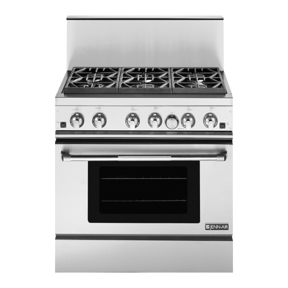
Professional 48", 36", 30" gas range
Hide thumbs
Also See for PRG3010:
- User manual (48 pages) ,
- Service (37 pages) ,
- Installation manual (56 pages)

Related Manuals for Jenn-Air PRG3010


Summary of Contents for Jenn-Air PRG3010
- Page 1 JENN-AIR Professional 4 8",36", 30" Gas RangeModels ,03WEST,OO,T. ST°EE,,,ORT...E_O @ @ O @ 0= Retain this manual for future reference. (17663 Rev. B) 8101 P601-60 (05-04-03)
-
Page 2: Model Identification
30'i GAS RANGE MODEL 36" GAS RANGE MODEL MODEL PRG3010 MODEL PRG3610 MODEL PRG4810... -
Page 3: Table Of Contents
Test AndAdjustment ....13-14 (this piece must be ordered separately) except the INSTALLER FINAL CHECK LIST ....PRG3010 model, which is shipped standard with a 9" low back. See Figure 1. WIRING DIAGRAM (PRG3010, PRG3610, PRG4810 Series) ..SCHEMATIC DIAGRAM (PRG3610, PRG4810, PRG3010 Series) .. -
Page 4: Importantinstallationinstructions
IMPORTANTINSTALLATIONINSTRUCTIONS STEP 1: VENTILATIONREQUIREMENTS Tested in accordance with ANSI Z21.1-1993 Standard for A suitable exhaust hood must be installed above the Household Cooking Gas Appliances. range. The following chart indicates the minimum blower capacity recommended for hood ventilation. (Table 1 ). These ranges must be installed in conjunction with a suitable overhead vent hood. -
Page 5: Step 2: Cabinetpreparation
STEP 2: CABINETPREPARATION 1. The range is a free-standing unit. If the unit is to be Figure 3A/B and Table 2 (side view of range) for dimensions. placed adjacent to cabinets, the clearances shown in Figures 2A/B/C are required. The same clearances 3. - Page 6 High Shelf Backguard must be installed. These parts 8. Do not obstruct the flow of combustion and ventilation must be ordered separately, except for the PRG3010 air to the unit. which comes equipped with a Low Back. Figure 3A _\k\\\"...
-
Page 7: Step 3: Unpacking,Moving And Placing The Range
STEP 3: UNPACKING,MOVING AND PLACING THE RANGE CAUTION PROPER EQUIPMENT AND ADEQUATE MAN- POWER MUST BE USED IN MOVING RANGE TO AVOID DAMAGE TO THE UNIT OR THE FLOOR. UNIT IS HEAVY RESTS ON ADJUSTABLE STEEL LEGS. DO NOT LIFT THE RANGE BY THE OVEN DOOR HANDLES!! -
Page 8: Griddleadjustments
To remove the door, open the door and hold it all the way It is important that the two screws retaining the kick open. Close the hinge latches (see Figure 8) and release panel are secure to prevent accidental access to live the door. -
Page 9: Anti-Tip Installation Instructions
Concrete Or Cement Construction Hardware required: (2) sleeve anchors, lag bolts, and washers (not provided). Locate the bracket as described above. Drill the recommended size holes for the PRG3610 PRG3010 Mo_el 5/8" 7/8" hardware. Install the sleeve anchors into the holes and... -
Page 10: Step4: Electrical Connections
Verify the type of gas supplied to the location. Power Requirements 120 VAC, 60 Hz., single phase. The range is shipped from the factory set up and adjusted for natural gas or LP gas (propane), depending on model PRG3010- 4 Amp. Max. ordered. PRG3610- 7 Amp. Max. -
Page 11: Step 6: Backguardinstallation
CAUTION FIGURE 14 For Warranty coverage, Jenn-Air requires that burn- er adjustments be made by a qualified technician at ** The oven infra-red broiler burner has no air shutter the time of installation. Extreme care should be used and is not adjustable when used with natural gas. -
Page 12: Installerfinal Check List
Surface Burners INSTALLERFINAL CHECK LIST The surface burners are not adjustable. Proper operation is Placement of unit. achieved when the correct orifices for the gas supply are installed at the factory, based on model ordered. Specified clearance maintained to cabinet surfaces. Unit level - front to back, side to side. - Page 14 "13 < A4_:E...
-
Page 15: Wiring Diagram (Prg3010, Prg3610, Prg4810 Series)
SERV[CE LIO_I OUAL VN I0 -i.-- -i.-- u") -i.--... - Page 18 < ii_ _ ¸¸¸ i_¸¸...
Need help?
Do you have a question about the PRG3010 and is the answer not in the manual?
Questions and answers