
Related Manuals for Jenn-Air PRG4810NP


Summary of Contents for Jenn-Air PRG4810NP
- Page 1 Professional 48², 36², 30² Gas Range Models 403 WEST FOURTH STREET, NORTH · NEWTON, IA 50208 Retain this manual for future reference. (17663 Rev. B) 8101P601-60 (05-04-03)
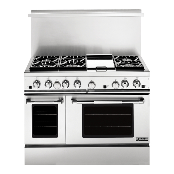
- Page 2 30² GAS RANGE MODEL 36² GAS RANGE MODEL MODEL PRG3010 MODEL PRG3610 48² GAS RANGE MODEL MODEL PRG4810...
-
Page 3: Table Of Contents
INTRODUCTION The features offered by the Jenn-Air professional series of gas ranges are certain to make the cooking experience more enjoyable and provide the novice or the experienced chef with years of enjoyment. A large capacity gas oven with a gas infrared broiler is included on the 30², 36²... -
Page 4: Important Installation Instructions
For best smoke elimination, the lower edge of the hood should be installed a minimum of 30² to a maximum of 36² above the range cooking surface, see figure 3. If the hood contains any combustible materials (i.e. a wood covering) it must be a minimum of 36²... -
Page 5: Step 2: Cabinet Preparation
STEP 2: CABINET PREPARATION 1. The range is a free-standing unit. If the unit is to be placed adjacent to cabinets, the clearances shown in Figures 2A/B/C are required. The same clearances apply to island installations. 2. The range can be placed in various positions with respect to the cabinet front, with the front either flush or projecting, depending on the countertop depth. - Page 6 6. When there is less than a 12² clearance between combustible material and the back edge of the range, (above the cooking surface) Jenn-Air Stub Back or High Shelf Backguard must be installed. These parts must be ordered separately, except for the PRG3010 which comes equipped with a Low Back.
-
Page 7: Step 3: Unpacking, Moving And Placing The Range
Remove the kick panel (see Figure 5) by removing two screws at the top and pulling forward. The range is held to the skid by two bolts in the front behind the kick panel (see Figure 5) and two L-brackets located on bottom flange of the range back (see Figure 7). -
Page 8: Griddle Adjustments
Adjust the corresponding rear corner of the range to an equal height of the counter, as the rear leveling legs are not accessible once the range is pushed into place. -
Page 9: Anti-Tip Installation Instructions
To check the range for proper installation of the anti-tip bracket: Use a flashlight and look underneath the bottom of the range to see that one of the rear leveling legs is engaged int eh bracket slot. (2) Wood Screws into Back Wall... -
Page 10: Step 4: Electrical Connections
FIGURE 9 STEP 5: GAS REQUIREMENTS Verify the type of gas supplied to the location. The range is shipped from the factory set up and adjusted for natural gas or LP gas (propane), depending on model ordered. Natural Gas Requirements Connection: 1/2²... -
Page 11: Step 6: Backguard Installation
(4) sheet metal screws provided. FIGURE 12 STEP 7: TEST AND ADJUSTMENT CAUTION For Warranty coverage, Jenn-Air requires that burn- er adjustments be made by a qualified technician at the time of installation. Extreme care should be used when adjustments are made after installation.* * Improper or lack of adjustments will void your warranty. -
Page 12: Installer Final Check List
Gas Supply Connection: 1/2 NPT with a minimum 5/8² diameter flex line. Site gas supply is compatible with range model, and sufficient pressure is available (see Gas Requirements on page 10). Manual gas shut off valve installed in an accessible location. - Page 13 JENN-AIR PRG3010 WIRING DIAGRAM Part No.: 16565-50 12/03 Rev. C...
- Page 14 JENN-AIR PRG3010 WIRING SCHEMATIC Part No.: 16565-50 12/03 Rev. C...
- Page 15 JENN-AIR PRG3610 WIRING DIAGRAM Part No.: 16560-50 12/03 Rev. C...
- Page 16 JENN-AIR PRG3610 WIRING SCHEMATIC Part No.: 16560-50 12/03 Rev. C...
- Page 17 JENN-AIR PRG4810 WIRING DIAGRAM Part No.: 16561-50 12/03 Rev. C...
- Page 18 JENN-AIR PRG4810 WIRING SCHEMATIC Part No.: 16561-50 12/03 Rev. C...
- Page 19 Cuisinières à gaz MISE EN professionnelles SERVICE de 121,9, 91,4 et 76,2 cm WEST FOURTH STREET, NORTH · NEWTON, IA 50208, ÉTATS- UNIS Veuillez conserver ce manuel pour référence ultérieure.
- Page 20 MODÈLE DE CUISINIÈRE À GAZ DE 76,2 CM MODÈLE DE CUISINIÈRE À GAZ DE 91,4 CM MODÈLE PRG3010 MODÈLE PRG3610 MODÈLE DE CUISINIÈRE À GAZ DE 121,9 CM MODÈLE PRG4810...
- Page 21 INTRODUCTION Les caractéristiques des cuisinières à gaz professionnelles Jenn-Air ne manqueront pas de rendre vos activités culinaires encore plus agréables et d’apporter au novice comme au cordon bleu des années d’agrément. Les fours de 76,2, 91,4 et 121,9 cm comportent un four de grande capacité...
-
Page 22: Consignes Importantes De Mise En Service
CONSIGNES IMPORTANTES DE MISE EN SERVICE Fonctionnement vérifié conformément à la norme ANSI Z21.1-1993 pour les appareils de cuisson ménagers fonctionnant au gaz. La mise en service de ces cuisinières doit comporter une hotte d’évacuation de puissance appropriée. (Voir l’étape 1 pour les besoins en évacuation d’air. -
Page 23: Étape 2 - Préparation De L'armoire
ÉTAPE 2 : PRÉPARATION DE L’ARMOIRE 1. La cuisinière est amovible. Si elle doit être placée adjacente à des armoires, les dégagements indiqués à la figures 2A/B/C sont exigés. Les mêmes dégagements sont exigés dans le cas d’îlots de cuisine. 2. - Page 24 (au-dessus de la surface de cuisson), il faut poser un dosseret extra court ou un dosseret Jenn-Air avec tablette. Ces éléments doivent être commandés séparément, sauf dans le cas du modèle PRG3010 qui...
-
Page 25: Étape 3 - Déballage, Déplacement Et Placement De La Cuisinière
ÉTAPE 3 : DÉBALLAGE, DÉPLACEMENT ET PLACEMENT DE LA CUISINIÈRE ATTENTION IL FAUT UTILISER L’ÉQUIPEMENT APPROPRIÉ ET AVOIR DU PERSONNEL SUFFISANT POUR DÉPLACER LA CUISINIÈRE AFIN D’ÉVITER D’ABÎMER L’APPAREIL OU LE PLANCHER. L’APPAREIL EST LOURD ET REPOSE SUR DES PIEDS RÉGLABLES EN ACIER. NE PAS SOULEVER LA CUISINIÈRE EN LA TENANT PAR LES POIGNÉES DU FOUR !! Le poids d’expédition de la cuisinière de 91,4 cm est... -
Page 26: Réglages Du Gril
Pour enlever la porte, l’ouvrir et la maintenir complètement ouverte. Fermer les verrous de charnière (voir la figure 8) et dégager la porte. La porte peut maintenant être enlevée en tirant doucement pour la soulever jusqu’à ce que les charnières soient sorties de l’encadrement. -
Page 27: Mise En Place Du Dispositif De Stabilisation
MISE EN PLACE DU DISPOSITIF DE STABILISATION REMARQUE : La cuisinière risque de basculer si elle n’est pas mise en place conformément aux consignes de mise en service fournies. Si le dispositif de stabilisation est utilisé correctement, il réduit le risque que la cuisinière ne - BASCULE. -
Page 28: Étape 4 - Raccordement À L'électricité
ÉTAPE 4 : RACCORDEMENT À L’ÉLECTRICITÉ Installation électrique nécessaire 120 VAC, 60 Hz., monophasé. PRG3010 - 4 A max. PRG3610 - 7 A max. PRG4810 - 13 A max. (Utiliser un circuit de 15 A.) Toujours débrancher le cordon d’alimentation de la prise murale ou couper l’appareil du secteur avant toute intervention. -
Page 29: Étape 6 - Pose Du Dosseret
FIGURE 12 ÉTAPE 7 : VÉRIFICATION ET RÉGLAGE ATTENTION Jenn-Air exige, dans le cadre de la garantie, que tous réglages sur les brûleurs soient réalisés par un technicien qualifié au moment de la mise en service. Tout réglage après la mise en service devra être effectué... -
Page 30: Liste De Vérification De L'installateur
Brûleurs de la surface de cuisine Les brûleurs de la surface de cuisine ne sont pas réglables. Les brûleurs functionnent correctement quand les orifices convenables à alimentation de gaz sont installés en usine selon le modèle commandé. *Si l’un des brûleurs de la surface de cuisine ne s’allume pas, détecter à... - Page 31 SCHÉMA DE CÂBLAGE PRG3010 JENN-AIR Référence : 16565-50 12/03 Rév. C...
- Page 32 SCHÉMA DE BRANCHEMENT PRG3010 JENN-AIR Référence : 16565-50 12/03 Rév. C...
- Page 33 SCHÉMA DE CÂBLAGE PRG3610 JENN-AIR Référence : 16560-50 12/03 Rév. C...
- Page 34 SCHÉMA DE BRANCHEMENT PRG3610 JENN-AIR Référence : 16560-50 12/03 Rév. C...
- Page 35 SCHÉMA DE CÂBLAGE PRG4810 JENN-AIR Référence : 16561-50 12/03 Rév. C...
- Page 36 SCHÉMA DE BRANCHEMENT PRG4810 JENN-AIR Référence : 16561-50 12/03 Rév. C...
- Page 37 Modelos profesionales MANUAL DE de estufas de gas INSTALACIÓN de 48”, 36” y 30” 403 WEST FOURTH STREET, NORTH · NEWTON, IA 50208 EE.UU. Conserve este manual como referencia futura.
-
Page 38: Identificación Del Modelo
MODELO DE ESTUFA DE GAS DE 30² ² ² ² MODELO DE ESTUFA DE GAS DE 36² ² ² ² MODELO PRG3010 MODELO PRG3610 MODELO DE ESTUFA DE GAS DE 48² ² ² ² MODELO PRG4810... -
Page 39: Advertencia
....Las características que ofrecen las estufas de gas de la serie profesional de Jenn-Air harán que la experiencia de cocinar sea más placentera y le darán al principiante o al cocinero experimentado muchos años de servicio fiel. -
Page 40: Instrucciones Importantes De Instalación
INSTRUCCIONES IMPORTANTES DE INSTALACIÓN Pruebas realizadas en conformidad con Estándar ANSI Z21.1-1993 para electrodomésticos de gas para cocinar. Estas estufas deben instalarse en conjunto con una campana superior de ventilación apropiada. (Vea el Paso 1: Requisitos de ventilación). Debido a la alta capacidad de calor profesional de esta unidad, debe prestarse atención especial al trabajo de instalación de la campana y los ductos para garantizar que cumpla con los códigos... -
Page 41: Paso 2: Preparación Del Gabinete
PASO 2: PREPARACIÓN DEL GABINETE 1. La estufa es una unidad independiente. Si se colocará adyacente a los gabinetes, se requerirán los espacios libres que se muestran en la figuras 2A/B/C. Los mismos espacios libres se aplican a las instalaciones en islas. - Page 42 (por encima de la superficie para cocinar), debe instalarse un protector posterior corto o uno con repisa alta de Jenn-Air. Estas piezas deben pedirse por separado, excepto en el modelo PRG3010, el cual Repisa alta...
-
Page 43: Paso 3: Desempacado, Transportacióny Colocación De La Estufa
PASO 3: DESEMPACADO, TRANSPORTACIÓN Y COLOCACIÓN DE LA ESTUFA PRECAUCIÓN DEBE UTILIZARSE EL EQUIPO Y MANO DE OBRA APROPIADOS CUANDO SE TRANSPORTE LA ESTUFA PARA EVITAR CAUSAR DAÑOS A LA UNIDAD O AL PISO. LA UNIDAD ES PESADA Y SE APOYA EN PATAS AJUSTABLES DE ACERO. ¡NO LEVANTE LA ESTUFA SUJETÁNDOLA POR LAS ASAS DE LA PUERTA! La estufa de 36”... -
Page 44: Ajustes De La Plancha De La Estufa
Para quitar la puerta, ábrala y sosténgala completamente abierta. Cierre los pasadores de las bisagras (vea la figura 8) y libere la puerta. Ésta puede quitarse levantándola suavemente, con las bisagras hacia arriba y fuera del marco. Las bisagras están ensambladas en la puerta y se quitarán del marco cuando la puerta se levante. -
Page 45: Dispositivo Estabilizador
INSTALACIÓN DEL DISPOSITIVO ESTABILIZADOR NOTA: Existe un riesgo de ladeo de la estufa si ésta no se instala de acuerdo con las instrucciones de instalación provistas. El uso apropiado de este dispositivo minimiza el riesgo de LADEO. Al usar el dispositivo el cliente debe continuar observando las precauciones de seguridad según se establece en el MANUAL DE USO Y CUIDADO y evitar usar la puerta del horno o la placa plegable como... -
Page 46: Paso 4: Conexiones Eléctricas
PASO 4: CONEXIONES ELÉCTRICAS Requisitos de energía 120 VCA, 60 Hz., monofásico. PRG3010 - 4 Amperios máx. PRG3610 - 7 Amperios máx. PRG4810 - 13 Amp. máx. (Use circuitos de 15 Amperios) Siempre desconecte el cordón de suministro eléctrico del tomacorriente de la pared o desconecte el servicio antes de darle servicio a este electrodoméstico. -
Page 47: Paso 6: Instalación Del Protector Posterior
FIGURA 12 PASO 7: PRUEBA Y AJUSTE PRECAUCIÓN Para fines de la cobertura bajo la garantía, Jenn-Air requiere que los ajustes de los quemadores los realice un técnico calificado al momento de la instalación. Debe tenerse cuidado extremo cuando se hagan los ajustes después de la instalación.*... -
Page 48: Lista De Verificación Final Del Instalador
Quemadores superiores Los quemadores superiores no son ajustables. Los quemadores funcionan correctamente cuando los orificios apropriados para la fuente de gas están instalados en fábrica, según el modelo pedido. *Si una de las quemadores superiores no se enciende, compruebe el encendedor escuchando un sonido que chasca. - Page 49 DIAGRAMA DE CABLEADO JENN-AIR PRG3010 Parte No.: 16565-50 12/03 Rev. C...
-
Page 50: Diagrama De Cableado (Series Prg3010, Prg3610, Prg4810)
ESQUEMA DE CABLEADO JENN-AIR PRG3010 Parte No.: 16565-50 12/03 Rev. C... -
Page 51: Diagrama Esquemático (Series Prg3610, Prg4810, Prg3010)
DIAGRAMA DE CABLEADO JENN-AIR PRG3610 Parte No.: 16560-50 12/03 Rev. C... - Page 52 ESQUEMA DE CABLEADO JENN-AIR PRG3610 Parte No.: 16560-50 12/03 Rev. C...
- Page 53 DIAGRAMA DE CABLEADO JENN-AIR PRG4810 Parte No.: 16561-50 12/03 Rev. C...
- Page 54 ESQUEMA DE CABLEADO JENN-AIR PRG4810 Parte No.: 16561-50 12/03 Rev. C...
- Page 55 NOTAS...
- Page 56 403 WEST FOURTH STREET, NORTH · NEWTON, IA 50208...
Need help?
Do you have a question about the PRG4810NP and is the answer not in the manual?
Questions and answers