NCR RealPOS 70 User Manual
Hide thumbs
Also See for RealPOS 70:
- User manual (195 pages) ,
- User manual (306 pages) ,
- User manual (160 pages)
Advertisement
Quick Links
Download this manual
See also:
User Manual
NCR 7402 RealPOS 70 user Manual
NCR 7402 RealPOS 70 user Manual
NCR 7402 RealPOS 70 user Manual
NCR 7402 RealPOS 70 user Manual
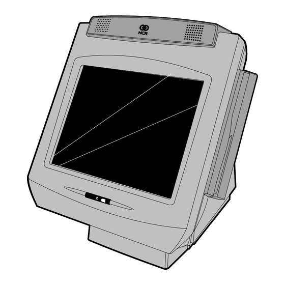
NCR RealPOS 70 (7402)
Release 1.4
User Guide
B005‐0000‐1463
Issue N
Advertisement

Related Manuals for NCR RealPOS 70


Summary of Contents for NCR RealPOS 70
- Page 1 NCR 7402 RealPOS 70 user Manual NCR 7402 RealPOS 70 user Manual NCR 7402 RealPOS 70 user Manual NCR 7402 RealPOS 70 user Manual NCR RealPOS 70 (7402) Release 1.4 User Guide B005‐0000‐1463 Issue N ...
- Page 2 Table of Contents Chapter 1: Product Overview Introduction ................... 1‐1 Optional Configurations ..............1‐2 Model and Serial Numbers..............1‐3 Terminal Dimensions and Weights ............ 1‐5 Hinged LCD................... 1‐5 Integrated Hardware ................1‐6 Operating Systems ................. 1‐7 Key Service Advantages ..............1‐8 Removable Motherboard Sled ............1‐8 Removable Power Supply ............. 1‐8 Removable Hard Disk..............1‐8 Hardware Module Descriptions ............1‐9 Motherboard ................... 1‐9 Processor/Chip Set ..............
- Page 3 Cash Drawer Support.............. 1‐17 MSR .................... 1‐17 Retail Daughter Card ..............1‐18 PCI Boards ..................1‐18 PCI Riser Board ................ 1‐18 PCMCIA Adapter Board............1‐18 Dual RS‐232 Adapter ............... 1‐18 Storage Media ................1‐19 HARD DISK DRIVE..............1‐19 Compact Flash ................1‐19 Operator Display ................1‐20 LCD Panel ................. 1‐20 LVDS ..................1‐20 Inverter ..................1‐21 Touch Screen................1‐21 Adjusting the Display Angle ..........
- Page 4 Compatibility..................1‐29 LAN Communications..............1‐29 Application Programmability............. 1‐29 Operating System Information........... 1‐29 System Configuration Diagram ............1‐30 Chapter 2: Installing the Terminal Introduction ................... 2‐1 Installation Summary..............2‐1 Installation Restrictions................ 2‐2 Peripheral Cable Routing..............2‐3 Installing Peripherals................2‐4 Accessing the Cable Connectors........... 2‐5 Cable Connector Identification............. 2‐6 PS/2 Keyboard/Mouse Cable Connections ......... 2‐7 Mouse Installation Restriction..........2‐7 Opening the Display Cabinet ............2‐8 12.1” and 15” Models..............2‐9 17” Models ................2‐10 Powering Up the Terminal ..............
- Page 5 Hiding the Cursor ................3‐4 Other Serial Devices Do Not Function ........3‐7 Touch Calibration Procedures............3‐12 Calibration Flow Chart ..............3‐13 3‐Point Calibration ............... 3‐14 Linearization ................. 3‐18 Other Controls..................3‐23 Main Tab ..................3‐23 Controller ID................3‐23 Controller Type ................ 3‐23 Firmware Version ..............3‐23 Touch Settings Tab ............... 3‐24 Touch Modes ................3‐25 Right‐Click Tool ............... 3‐26 Touch Sound ................3‐26 Double‐Click Speed ..............
- Page 6 Touch Calibration Procedures............. 4‐2 Installing the Touch Driver ............4‐2 Calibration Flow Chart ..............4‐8 2‐Point Calibration Procedure ............4‐9 Cursor Stabilization Procedure ..........4‐13 25‐Point Linearization Procedure..........4‐16 Restore Defaults Procedure............4‐20 Changing From 4‐Point to 2‐Point Calibration....... 4‐22 Touch Performance................4‐25 Chapter 5: Touch Screen Calibration – Windows (MT 5.64, SR6) General Guidelines ................5‐1 Considerations When Replacing or Re‐Imaging the Hard Drive....................5‐1 Installing the Touch Driver ..............5‐2 Touch Calibration Procedures............. 5‐7 Calibration Flow Chart ..............5‐8 2‐Point Calibration Procedure ............5‐9 Cursor Stabilization Procedure ..........
- Page 7 Printers ....................8‐1 NCR 7167 Printer................8‐1 NCR 7197 Printer................8‐2 Installing the Transaction Printer ..........8‐3 Remote Displays ................... 8‐5 5964 12.1‐Inch Touch Screen ............8‐5 Features ..................8‐6 Installing an NCR 5964 12.1‐inch Touch LCD ....... 8‐8 5964 15‐Inch Touch Screen ............8‐11 Installing an NCR 5964 15‐inch Touch LCD ......8‐12 5966 15‐Inch Touch Screen ............8‐15 Installing an NCR 5966 Monitor ..........8‐16 5942 12.1‐INCH Color LCD............8‐19 NCR 5942 12.1‐Inch LCD Monitor Cable Connections ... 8‐20 NCR 5942 15‐Inch LCD Monitor Cable Connections ....8‐21...
- Page 8 Installing an NCR 5954 USB DynaKey ......... 8‐23 7452‐K419 15‐Inch Color CRT............. 8‐25 NCR 5932 Keyboards ................. 8‐26 109‐Key USB Keyboard ............... 8‐26 Features ..................8‐27 115‐Key PS/2 Big Ticket Keyboard..........8‐29 68‐Key PS/2 POS Keyboard............8‐29 Features ..................8‐30 Remote Customer Displays ............... 8‐33 NCR 5972 2x20 Customer Display ..........8‐33 Tall Post Models ............... 8‐33 Desktop Models................ 8‐34 Features ..................8‐34 NCR 5973 2x20 International VFD Customer Display.... 8‐35 Features ..................8‐35 Installing an NCR 5972 Remote Customer Display ....
- Page 9 Chapter 10: 2x20 Customer Display Interface Introduction ..................10‐1 General Specifications ................ 10‐1 Serial Communication Interface ............10‐1 Command Codes................. 10‐2 User Defined Character Definition (08h, CODE, Byte1…Byte5)................10‐2 Character Table Select (09h, TABLE CODE) ......10‐3 Clear Display (12h)............... 10‐3 Luminance Control (11h, LUMINANCE)......... 10‐3 Cursor Position (10h, POSITION) ..........10‐4 Reset (13h) ..................10‐4 Character Tables and Codes ............10‐4 CP437 ..................10‐5 CP858 ..................10‐6 CP866 ..................10‐7 CP932 ..................
- Page 10 Reset (00h) ..................11‐7 Set Luminance (01h, LUMINANCE) ......... 11‐7 Set Y Address Register (02h, YAR) ..........11‐7 Set X Address Register (03h, XAR) ..........11‐8 Set Display Control Bits (04h, DCB) .......... 11‐8 Write Data Byte (05H, DATA) ............ 11‐8 Write Data Page (06h, BYTE1, BUTE2,... BYTE1024)....11‐8 Write Data w/Shift (07h, DIRECTION, ROW, BYTE1, BYTE2,... BYTE32)................. 11‐9 Data Write Mode (08h, MODE)..........11‐10 Character Write Mode (09h, MODE) ........11‐10 Invert Screen (0Ah) ..............11‐11 Reserved (0Bh ‐ 0Fh) ..............11‐11 Character Codes (10h ‐ FFh) ............11‐11 5X7 Character Table ..............11‐12 10x14 Character Table..............
-
Page 11: Chapter 16: Bios Updating Procedures
Header file: DarlingtonCDSample.h......... 12‐26 Chapter 13: Wedge to USB MSR Software Migration Overview....................13‐1 Software Requirements ..............13‐2 Potential Operational Differences............. 13‐4 Deployment Considerations.............. 13‐5 Local Update ................. 13‐5 Remote Deployment ..............13‐5 Chapter 14: Maintenance Cabinet and Touch Screen Cleaning Procedures ......14‐1 Cleaners/Solvents to Use ............. 14‐1 Cleaners/Solvents to NOT Use ........... 14‐2 Cooling Vent Cleaning ............... 14‐3 MSR Cleaning Procedures ..............14‐4 Chapter 15: Operating System Recovery Introduction ..................15‐1 Prerequisites .................. 15‐1 OS Recovery Procedures.............. - Page 12 xiii Appendix A: Cables Printer Cables ..................A‐1 Scanner Cables..................A‐3 7872 or 7875 Scanner/Scale (RS‐232) ...........A‐3 7892 Scanner (Powered RS‐232) ..........A‐3 7882 Scanner (Powered RS‐232) ..........A‐3 7837 Scanner (Powered RS‐232) ..........A‐4 7837 Scanner (RS‐232, External Power) ........A‐4 Display Cables..................A‐5 VGA Display, Mono..............A‐5 VGA Display, Color ..............A‐5 CRT AC Power Extension ............A‐5 5972 VFD Customer Display (Powered RS‐232) .......A‐6 DVI to DVI..................A‐6 PS/2 ‐ RS‐232 & Power ..............A‐6 LCD Power Cable ................A‐7 Cash Drawer Cables ................A‐8 Dual Cash Drawer, Y‐Cable............A‐8 Cash Drawer, Extension Cable ............A‐8 Communications Cable ...............A‐8 Ethernet, 10/100BaseT ..............A‐8 Keyboard Cables ..................A‐9 PS/2 Keyboard Extension .............A‐9 Signature Capture/Electronic Payment Terminal Cable ....A‐9 5945/5992 EPT (RS‐232 w/Power)..........A‐9 Power Cables (AC)................A‐10...
- Page 13 Appendix B: Feature Kits Appendix C: Memory Map DOS Considerations..............C‐2 Appendix D: IRQ Settings Interrupts ..................D‐1 Default Settings .................D‐1 Optional Settings...............D‐2 ...
- Page 14 This is a “Table of Contents preview” for quality assurance The full manual can be found at http://the-checkout-tech.com/estore/catalog/ We also offer free downloads, a free keyboard layout designer, cable diagrams, free help and support. http://the-checkout-tech.com : the biggest supplier of cash register and scale manuals on the net...
Need help?
Do you have a question about the RealPOS 70 and is the answer not in the manual?
Questions and answers