Seastar Solutions Optimus 360 Operation Manual
Joystick control system for engines with integrated electronic shift and throttle
Hide thumbs
Also See for Optimus 360:
- Manual (264 pages) ,
- Installation manual (104 pages) ,
- Operating instructions & user manual (80 pages)

Related Manuals for Seastar Solutions Optimus 360


Summary of Contents for Seastar Solutions Optimus 360
- Page 1 OPERATION INSTRUCTIONS AND USER'S MANUAL w w w . s e a s t a r s o l u t i o n s . c o m S I X T Y T W O Joystick Control System for ISO 9001 Engines with Integrated Electronic Shift and Throttle...
- Page 2 Yacht Council (http://www.abycinc.org) NMEA 2000 is a registered trademark of the National Marine ® Electronics Association. Optimus, Optimus 360, SeaStar, and BayStar are all trademarks of SeaStar Solutions. Evinrude, Suzuki, Yamaha, and Yanmar are trademarks of their respective holders. California...
- Page 3 Thank you for choosing an Optimus 360 Joystick Control System by SeaStar Solutions. You have chosen a state of the art vessel control system that will provide years of effortless and trouble free steering performance. About this Book This User’s manual contains the information you need to safely operate and maintain your vessel control system.
- Page 4 This page left intentionally blank. © 2013 SeaStar Solutions Optimus 360 Joystick Control System, Rev. C...
-
Page 5: Table Of Contents
3.2 Control Head (EST System) ........12 3.3 Joystick ..............13 3.4 CANtrak Display ............14 3.5 Circuit Breakers for Optimus 360 System ....14 3.6 Pump Control Module (PCM) ........15 3.7 Hydraulic Pumps ............15 3.8 SmartCylinders ............16 3.9 Steering Service Valves .......... - Page 6 14. warranty ................63 14.1 Statement of Limited Warranty ........63 14.2 Return Goods Procedure .......... 63 appendIX a - Specifications ............. 64 appendIX B - trailering and Storage ......... 65 © 2013 SeaStar Solutions Optimus 360 Joystick Control System, Rev. C...
-
Page 7: Safety Instructions
It IS crItIcaL that you read and underStand aLL the poIntS noted. warnInG the optImuS 360 SyStem muSt onLy Be InStaLLed By an authorIzed deaLer or oem. Safe operation of the steering system depends upon proper installation and maintenance of the system, and the common sense, safe judgment, knowledge, and expertise of the operator. - Page 8 DO NOT use cleaners containing ammonia, acids, or any other corrosive ingredients on any Optimus components. maintenance Maintain your Optimus 360 System as directed in Section 11 of this manual. Keep our waters clean for all current and future users. Dispose of all fluids in accordance with your local regulations.
-
Page 9: Safety Labels
LaBeLS BeLow ShouLd caLL attentIon to the poSSIBLe hazardS aSSocIated wIth the equIpment Shown Later In thIS manuaL (See SectIon 3.1) hydraulic pump Labels CAUTION Figure 1-1. Hydraulic pump labels. © 2013 SeaStar Solutions Optimus 360 Joystick Control System, Rev. C... - Page 10 Safety Labels (continued) pump control module (pcm) Labels Figure 1-2. PCM labels. Smartcylinder Labels Figure 1-3. SmartCylinder labels. © 2013 SeaStar Solutions Optimus 360 Joystick Control System, Rev. C...
- Page 11 Safety Labels (continued) Steering Service valve Labels To be installed close to the service valve. Figure 1-4. Steering service valve labels. © 2013 SeaStar Solutions Optimus 360 Joystick Control System, Rev. C...
-
Page 12: Abbreviations
Speed Over Water STBD Starboard (right when facing the front of the boat) Switch Wide Open Throttle Note: Some abbreviations not listed here may be found in their respective sections. © 2013 SeaStar Solutions Optimus 360 Joystick Control System, Rev. C... -
Page 13: Definitions
A single handle joystick control device that integrates the steering, the gear shift, and the throttle control for multiple engines into one easy-to-use device to provide docking control of the vessel. © 2013 SeaStar Solutions Optimus 360 Joystick Control System, Rev. C... - Page 14 This page left intentionally blank. © 2013 SeaStar Solutions Optimus 360 Joystick Control System, Rev. C...
-
Page 15: Introduction
A CANtrak display shows system operation and fault warnings. The CANtrak display also permits system sensitivity and configuration adjustments. The Optimus 360 system is designed and tested to exceed ABYC safety standards, and includes many advancements to make the system as fail-safe as possible. These include redundant sensors, fault-tolerant communications, self-monitoring, and fault communications to notify and advise the operator in case of fault. -
Page 16: Optimus 360 System Diagram
POWER SOURCE SOURCE COMPONENTS NOT SUPPLIED BY SEASTAR SOLUTIONS SERVICE SERVICE VALVE VALVE HYDRAULIC HYDRAULIC HOSE HOSE SMART SMART CYLINDER CYLINDER Figure 2-1. Optimus 360 system diagram, single station. © 2013 SeaStar Solutions Optimus 360 Joystick Control System, Rev. C... -
Page 17: Component Identification
EPS Front Mount Helm EPS Sport Plus Tilt Helm EPS Classic Tilt Helm EPS Rear Mount Helm Figure 3-1. EPS Helm configurations. © 2013 SeaStar Solutions Optimus 360 Joystick Control System, Rev. C... -
Page 18: Control Head (Est System)
The control head operates the gear shift and the throttle for each engine. For detailed control head operation, refer to your engine manufacturer’s installation manual. Figure 3-2. Example Control Head shown. © 2013 SeaStar Solutions Optimus 360 Joystick Control System, Rev. C... -
Page 19: Joystick
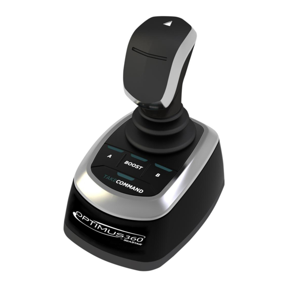
The joystick can only take control of the vessel when the shift and throttle control head is at neutral idle. See Section 6.0 for detailed Joystick operation. Figure 3-3. Joystick. © 2013 SeaStar Solutions Optimus 360 Joystick Control System, Rev. C... -
Page 20: Cantrak Display
See Section 7.0 for CANtrak usage. Figure 3-4. CANtrak display. 3.5 Circuit Breakers for Optimus 360 System These are supplied by the installer and may be mounted in a variety of locations. Check near the batteries, in the circuit breaker box, or near the pump control modules or hydraulic pumps. -
Page 21: Pump Control Module (Pcm)
Electronic Power Steering Fluid. The pumps have the steering fluid reservoir and this is where the fluid level is checked and steering fluid is added. Figure 3-6. Hydraulic steering pump. © 2013 SeaStar Solutions Optimus 360 Joystick Control System, Rev. C... -
Page 22: Smartcylinders
CANtrak display or in Section 10.2. Figure 3-8. Steering service valve warnInG wear a coaSt Guard-approved perSonaL fLotatIon devIce (pfd) when manuaLLy reaLIGnInG enGIneS. © 2013 SeaStar Solutions Optimus 360 Joystick Control System, Rev. C... -
Page 23: Steering System Operation
4.0 StEErINg SyStEm opEratIoN The steering portion of the Optimus 360 system provides fingertip steering control of multiple high-powered engines. The system provides both power and the adjustment of a number of parameters so the operator has perfect boat response under all conditions. - Page 24 This page left intentionally blank. © 2013 SeaStar Solutions Optimus 360 Joystick Control System, Rev. C...
-
Page 25: Control Head Operation
Be very cautIouS when fIrSt enGaGInG the GearS. Your Optimus 360 joystick control system is designed to work with a variety of different EST systems provided by different engine manufacturers. Each engine manufacturer will have their own unique transfer routine to switch from joystick control back to conventional shift and throttle control. - Page 26 This page left intentionally blank. © 2013 SeaStar Solutions Optimus 360 Joystick Control System, Rev. C...
-
Page 27: Joystick Operation
This section of the manual gives a detailed description of all of its capabilities and how to get the maximum benefit from this powerful feature. The Optimus 360 Joystick Quick Reference Guide, provided with the system, gives summary and reminder information on its operation and should be kept on the vessel at all times. -
Page 28: Joystick Fundamentals
* See section 10 for fault handling information. a and c Buttons Reserved for future use. Not active at this time. © 2013 SeaStar Solutions Optimus 360 Joystick Control System, Rev. C... - Page 29 See the following pages for examples of each of the primary operational modes. warnInG In the event of an enGIne StaLL, onLy the forward/reverSe mode IS avaILaBLe. reStart StaLLed enGIne or SwItch to conventIonaL controLS. © 2013 SeaStar Solutions Optimus 360 Joystick Control System, Rev. C...
- Page 30 – rotate to Steer Figure 6-2. prImary motIon – SIdewayS correctIon – rotate to BIaS headInG Figure 6-3. NEutral NEutral correctIon – prImary motIon – SIdewayS forward/reverSe to dIaGonaL rEvErSE Figure 6-4. © 2013 SeaStar Solutions Optimus 360 Joystick Control System, Rev. C...
-
Page 31: Joystick Tips
7. The control head must be active at the helm station with the joystick that will be used and the control handles must be in neutral and idle at that station. © 2013 SeaStar Solutions Optimus 360 Joystick Control System, Rev. C... -
Page 32: Joystick Operation Examples
3b. If the boat does not stay centered due to wind or current while holding the joystick to the side, just push or pull the joystick fore/aft to correct. 4. Once close to the dock, return the joystick to the center position. © 2013 SeaStar Solutions Optimus 360 Joystick Control System, Rev. C... - Page 33 6.3 Joystick Operation Examples (continued) wind Figure 6-8. Figure 6-9. CURRENT Figure 6-10. Figure 6-11. © 2013 SeaStar Solutions Optimus 360 Joystick Control System, Rev. C...
- Page 34 3. As the boat approaches the slip pull the joystick backwards to stop the boat in front of the slip. Return the joystick to the home position when the boat stops. Figure 6-12. Figure 6-13. Figure 6-14. © 2013 SeaStar Solutions Optimus 360 Joystick Control System, Rev. C...
- Page 35 5. Pull the joystick back to move the boat into the slip. 6. A short bump forward on the joystick will stop the boat in position. Figure 6-15. Figure 6-16. Figure 6-17. © 2013 SeaStar Solutions Optimus 360 Joystick Control System, Rev. C...
- Page 36 This page left intentionally blank. © 2013 SeaStar Solutions Optimus 360 Joystick Control System, Rev. C...
-
Page 37: Cantrak Display
7.0 caNtrak DISplay 7.1 Purpose The Optimus 360 CANtrak display has an easy to navigate menu system, adjustable backlighting for night use and includes a cover to protect it from the sun when not in use. Figure 7-1. CANtrak display, All Helms Active screen. -
Page 38: Cantrak Display Navigation
Increases the setting of a selected item Accepts a given statement or condition and advances to the next screen Moves the unit back one level. CANtrak display lighting CANtrak display contrast (monochrome model only) © 2013 SeaStar Solutions Optimus 360 Joystick Control System, Rev. C... -
Page 39: Cantrak Display Map - All Helms Active
LO Speed Helm Effort HI Speed Helm Effort AP Helm Effort DISPLAY Contrast Brightness Figure 7-3. CANtrak display map. * Some installations may not have this feature accessible. Contact dealer/builder. © 2013 SeaStar Solutions Optimus 360 Joystick Control System, Rev. C... -
Page 40: Display Screens
7.4.2 Diagnostics (DIAG) Screen The Diagnostics screen gives the user access to a list of all active warning faults, as well as network node information. Figure 7-5. Diagnostics screen. © 2013 SeaStar Solutions Optimus 360 Joystick Control System, Rev. C... -
Page 41: Adjust (Adj) Screen
Sets the steering resistance when autopilot is engaged. To prevent accidental course corrections with the wheel this should be set slightly higher than the high speed effort. It is adjustable between 0 and 100. © 2013 SeaStar Solutions Optimus 360 Joystick Control System, Rev. C... - Page 42 Figure 7-7. Change of helm settings with speed. * Some installations may not have this feature accessible. Contact dealer/builder. © 2013 SeaStar Solutions Optimus 360 Joystick Control System, Rev. C...
-
Page 43: Display (Disp) Screen
The Display screen allows adjustment of the brightness and contrast (on monochrome models only) of the CANtrak display. These should be adjusted to provide good daytime and night time visibility of the display. Figure 7-8. Display adjustment screen. © 2013 SeaStar Solutions Optimus 360 Joystick Control System, Rev. C... - Page 44 This page left intentionally blank. © 2013 SeaStar Solutions Optimus 360 Joystick Control System, Rev. C...
-
Page 45: First Time Use
The detent pressure and lever drag may be user adjustable. Refer to the documentation provided with your control head. Figure 8-1. Control Head lever positions. © 2013 SeaStar Solutions Optimus 360 Joystick Control System, Rev. C... -
Page 46: Initial Start Up
8.2 Initial Start Up Turning on the ignition switch will turn on the Optimus 360 system. The CANtrak display will turn on and steering will become active at all helms. After reading the initial warning screen press the INFO button and follow the prompts for a system inspection. - Page 47 The joystick now has control of the system and is ready for use. Refer to Sections 4.0, 5.0 and 6.0 for detailed steering, control head and joystick operation. © 2013 SeaStar Solutions Optimus 360 Joystick Control System, Rev. C...
-
Page 48: System Inspection
Injury and/or death. 1. check steering fluid level in all steering pumps. Each Optimus 360 hydraulic pump has a steering fluid reservoir. Ensure the fluid level is between the MIN and MAX marks on the reservoir as shown in the figure below. Use only SeaStar Electronic Power Steering Fluid in the Optimus 360 System. - Page 49 It IS recommended the fuLL SyStem InSpectIon Be revIewed on a reGuLar BaSIS to retaIn famILIarIty. © 2013 SeaStar Solutions Optimus 360 Joystick Control System, Rev. C...
-
Page 50: Installation Checks
Figure 8-5. Engine side view when tilted. 2. Sensor cable – Confirm that the SmartCylinder Sensor Cable is tied securely to the hoses with gradual bends as shown figure 8-6. © 2013 SeaStar Solutions Optimus 360 Joystick Control System, Rev. C... -
Page 51: Initial Sea Trial
– Try all the various modes and using both primary and proper helm operation. secondary actions. If adjustments to the system are required see Section 7.4.3 for steering adjustments or contact your dealer. © 2013 SeaStar Solutions Optimus 360 Joystick Control System, Rev. C... - Page 52 This page left intentionally blank. © 2013 SeaStar Solutions Optimus 360 Joystick Control System, Rev. C...
-
Page 53: System Use
360 is turned on. The conventional steering portion of the Optimus 360 system is designed to operate much like a conventional hydraulic steering system. The boat can be steered from any helm without requiring additional steps to transfer control. -
Page 54: Autopilot Operation
InStructIon compLeteLy Before enGaGInG the autopILot mode. The Optimus 360 steering system is designed to interface with many autopilot controllers. See your Autopilot’s documentation for specific model compatibility. On boats with an autopilot the steering effort may be noticeably higher when the autopilot is engaged. -
Page 55: System Faults & Hazards
In the case of a Joystick danger fault, in addition to the CANtrak message and buzzer, the joystick Take Command button light will flash red quickly (5 times per second). © 2013 SeaStar Solutions Optimus 360 Joystick Control System, Rev. C... -
Page 56: Warning
Section 10.2.3 for warning fault handling specifics. In the case of a Joystick warning fault, in addition to the CANtrak message and buzzer, the joystick Take Command button light will alternate flashing red and blue. © 2013 SeaStar Solutions Optimus 360 Joystick Control System, Rev. C... -
Page 57: System Fault Handling
Provides detailed instructions on how to proceed. In the case of a danger fault, this will instruct the operator what to do and how to proceed should Limp Home mode be required. © 2013 SeaStar Solutions Optimus 360 Joystick Control System, Rev. C... -
Page 58: Limp Home
Figure 10-2. Limp home instructions, all steering disabled. © 2013 SeaStar Solutions Optimus 360 Joystick Control System, Rev. C... - Page 59 ONE of the engines. The CANtrak will instruct the operator to realign the non-responsive engine, tilt it out of the water, and proceed home immediately using the responsive engine. Figure 10-3. Limp home instructions, no steering on one engine. © 2013 SeaStar Solutions Optimus 360 Joystick Control System, Rev. C...
-
Page 60: Warning Fault Handling
In rare cases there may be multiple Warning faults at the same time. You can view a list of all active warning faults by selecting Active Warnings from the Diagnostics (DIAG) screen. © 2013 SeaStar Solutions Optimus 360 Joystick Control System, Rev. C... - Page 61 Figure 10-5. Run screen with system warning. Some system warning faults may result in a reduced steering response. This means that the system will continue to steer normally but may respond more slowly. © 2013 SeaStar Solutions Optimus 360 Joystick Control System, Rev. C...
-
Page 62: System Fault Handling - Example
The vessel should be returned to port immediately for repair. © 2013 SeaStar Solutions Optimus 360 Joystick Control System, Rev. C... -
Page 63: Cantrak Loss Of Display
5. Close Steering Service Valves 6. Fully tilt affected engine and switch it off. 7. Return to port. If shift and throttle response is lost, refer to the engine manufacturer’s documentation for instructions. © 2013 SeaStar Solutions Optimus 360 Joystick Control System, Rev. C... -
Page 64: Buzzer
A typical cause might be a very low battery. When this happens the CANtrak will advise the operator of the condition, indicate the reason, and supply instructions. warnInG proceed wIth cautIon untIL the fauLt IS corrected and normaL operatIon returnS. © 2013 SeaStar Solutions Optimus 360 Joystick Control System, Rev. C... -
Page 65: Maintenance
4. Check for signs of corrosion. If corrosion is present contact your dealer or SeaStar Solutions. 5. Check all electrical harnesses and mechanical cables for chaffing and wear. © 2013 SeaStar Solutions Optimus 360 Joystick Control System, Rev. C... - Page 66 SyStem. GREASE SUPPORT ROD, TILT TUBE & SUPPORT BRACKET HOLE GREASE SUPPORT ROD, TILT TUBE & SUPPORT BRACKET HOLE Figure 11-1. Grease points on cylinder mounts. © 2013 SeaStar Solutions Optimus 360 Joystick Control System, Rev. C...
-
Page 67: Troubleshooting
GuIde onLy and IS not reSponSIBLe for any conSequenceS reSuLtInG from Incorrect dISmantLInG repaIrS. Optimus 360 will provide years of safe reliable performance with a minimum of service if properly installed. Optimus 360 steering systems have been designed with protection... -
Page 68: Replacement Parts
Brake fLuId. SeaStar electronic power Steering fluid part numbers Quart HA5482 For full listing of part numbers, please refer to the Optimus 360 Installation Manual (Book 60), part no. 682102. © 2013 SeaStar Solutions Optimus 360 Joystick Control System, Rev. C... -
Page 69: Warranty
In such a case SeaStar Solutions products found to be defective and covered by this warranty, will be replaced at SeaStar Solutions’ option, and returned to the customer. -
Page 70: Appendix A - Specifications
Maximum System Pressure: 1200 PSI # of wheel turns: Variable from 3.5 to 8 Typical Average Current Draw: ~6 to 8 Amps Oil Type: SeaStar Electronic Power Steering Fluid © 2013 SeaStar Solutions Optimus 360 Joystick Control System, Rev. C... -
Page 71: Appendix B - Trailering And Storage
The weight of the engines will keep them from shifting. STEERING LOCK CLIPS (SEE WARNING) STEERING LOCK CLIPS (SEE WARNING) STEERING CYLINDER Figure B-1. Steering cylinder lock clips. © 2013 SeaStar Solutions Optimus 360 Joystick Control System, Rev. C... - Page 72 _______________________________________________ notes _______________________________________________ _______________________________________________ _______________________________________________ _______________________________________________ _______________________________________________ _______________________________________________ _______________________________________________ _______________________________________________ _______________________________________________ _______________________________________________ _______________________________________________ _______________________________________________ _______________________________________________ _______________________________________________ _______________________________________________ _______________________________________________ _______________________________________________ _______________________________________________ _______________________________________________ © 2013 SeaStar Solutions Optimus 360 Joystick Control System, Rev. C...
- Page 73 © 2013 SeaStar Solutions Optimus 360 Joystick Control System, Rev. C...
- Page 74 © 2013 SeaStar Solutions Optimus 360 Joystick Control System, Rev. C...
- Page 76 SEASTAR SOLUTIONS 3831 NO.6 ROAD RICHMOND, B.C. CANADA V6V 1P6 FAX 604-270-7172 www.seastarsolutions.com ISo 10592 © 2013 MARINE CANADA ACQUISITION INC. DBA SEASTAR SOLUTIONS PRINTED IN CANADA FORM NO. 682113 01/14 REV. C...
Need help?
Do you have a question about the Optimus 360 and is the answer not in the manual?
Questions and answers