Advertisement
Table of Contents
- 1 Table of Contents
- 2 Warning Decal Placement
- 3 Important Precautions
- 4 Before You Begin
- 5 Part Identification Chart
- 6 Assembly
- 7 How to Connect Power Cord
- 8 Operation and Adjustment
- 9 How to Fold and Move the Treadmill
- 10 Troubleshooting
- 11 Exercise Guidelines
- 12 Part List
- 13 Exploded Drawing
- 14 Ordering Replacement Parts
- 15 Limited Warranty
- Download this manual
Model No. PCTL79612.0
Serial No.
Write the serial number in the space
above for reference.
Serial Number
Decal
QUESTIONS?
If you have questions, or if parts
are damaged or missing, PLEASE
CONTACT OUR CUSTOMER
SERVICE DEPARTMENT
DIRECTLY.
CALL TOLL-FREE:
1-888-936-4266
Mon.–Fri., 7:30 until 16:30 ET
(excluding holidays)
OR E-MAIL US:
customerservice@iconcanada.ca
CAUTION
Read all precautions and instruc-
tions in this manual before using
this equipment. Save this manual
for future reference.
USER'S MANUAL
www.proform.com
Advertisement
Table of Contents

Related Manuals for Pro-Form Power 795 PCTL79612.0


Summary of Contents for Pro-Form Power 795 PCTL79612.0
- Page 1 Model No. PCTL79612.0 Serial No. USER’S MANUAL Write the serial number in the space above for reference. Serial Number Decal QUESTIONS? If you have questions, or if parts are damaged or missing, PLEASE CONTACT OUR CUSTOMER SERVICE DEPARTMENT DIRECTLY. CALL TOLL-FREE: 1-888-936-4266 Mon.–Fri., 7:30 until 16:30 ET (excluding holidays)
-
Page 2: Table Of Contents
TABLE OF CONTENTS WARNING DECAL PLACEMENT ............. . .2 IMPORTANT PRECAUTIONS . -
Page 3: Important Precautions
IMPORTANT PRECAUTIONS WARNING: To reduce the risk of burns, fire, electric shock, or injury to persons, read all important precautions and instructions in this manual and all warnings on your treadmill before using your treadmill. ICON assumes no responsibility for personal injury or property damage sus- tained by or through the use of this product. - Page 4 20. The heart rate monitor is not a medical 24. Never insert any object into any opening on device. Various factors, including the user’s the treadmill. movement, may affect the accuracy of heart rate readings. The heart rate monitor is 25.
-
Page 5: Before You Begin
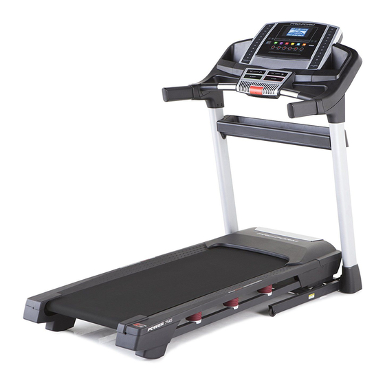
BEFORE YOU BEGIN Thank you for selecting the revolutionary PROFORM reading this manual, please see the front cover of this ® POWER 795 treadmill. The POWER 795 treadmill manual. To help us assist you, please note the product offers an impressive selection of features designed model number and serial number before contacting us. -
Page 6: Part Identification Chart
PART IDENTIFICATION CHART Use the drawings below to identify small parts used for assembly. The number in parentheses below each draw- ing is the key number of the part, from the PART LIST near the end of this manual. The number following the key number is the quantity used for assembly. -
Page 7: Assembly
ASSEMBLY • Assembly requires two persons. • Assembly requires the following tools: • Place all parts in a cleared area and remove the the included hex keys packing materials. Do not dispose of the packing materials until you finish assembly. one adjustable wrench •... - Page 8 3. Identify the Left Upright (89). Have a second person hold the Left Upright near the Base (94). See the inset drawing. Tie the wire tie in the Left Upright (89) securely around the end of the Upright Wire (81). Then, pull the other end of the Wire wire tie until the Upright Wire is routed through the Left Upright.
- Page 9 5. Identify the Left Base Cover (82) and the Right Base Cover (83). Slide the Left Base Cover onto the Left Upright (89). Slide the Right Base Cover onto the Right Upright (90). Do not press the Base Covers into place yet. Identify the Left Upright Cover (79) and the Right Upright Cover (80).
- Page 10 7. Attach the Left Handrail (88) to the Left Upright (89) with two 5/16" x 1" Screws (5), two 5/16" Star Washers (11), and a 5/16" x 1 1/4" Bolt (4). Do not fully tighten the Screws and Bolt yet. Attach the Right Handrail (87) in the same way.
- Page 11 10. With the help of a second person, hold the con- sole assembly near the Left Handrail (88). Connect the Upright Wire (81) to the console Console wire. See the inset drawing. The connectors Assembly should slide together easily and snap into place.
- Page 12 12. Firmly tighten the four 3/8" x 2 3/4" Screws (7) and the four 3/8" x 1 1/4" Screws (8) (only one side is shown). Press the Left Base Cover (82) and the Right Base Cover (83) onto the Base (94) until they snap into place.
- Page 13 15. Attach the Left Tray (107) and the Right Tray (108) to the console assembly with four #8 x 1/2" Screws (1). Console Assembly 16. IMPORTANT: See page 15 and plug in the power cord. Next, see page 17 and turn on IMPORTANT: the power.
- Page 14 17. IMPORTANT: Before you begin this step, make sure that you have read and followed all instructions in step 16. Raise the Frame (56) to the position shown. Have a second person hold the Frame until this step is completed. Orient the Storage Latch (53) so that the large barrel and the latch knob are oriented as shown.
-
Page 15: Operation And Adjustment
OPERATION AND ADJUSTMENT HOW TO CONNECT THE POWER CORD nominal 120-volt circuit capable of carrying 15 or more amps. To avoid overloading the circuit, do Use a Surge Suppressor not plug other electrical devices, except for low- power devices such as cell phone chargers, into Your treadmill, like other electronic equipment, can be the surge suppressor or into an outlet on the same circuit. - Page 16 CONSOLE DIAGRAM FEATURES OF THE CONSOLE can use an array of tools to analyze your results and monitor your progress toward your fitness goals. To purchase a SYNC at any time, call the telephone The treadmill console offers an impressive array of number on the front cover of this manual.
- Page 17 HOW TO TURN ON THE POWER HOW TO USE THE MANUAL MODE IMPORTANT: If the treadmill has been exposed to 1. Insert the key into the console. cold temperatures, allow it to warm to room tem- perature before turning on the power. If you do not See HOW TO TURN ON THE POWER at the left.
- Page 18 4. Change the incline of the treadmill as desired. The Distance dis- play—This display will To change the incline of the treadmill, press the show the distance that Incline increase or decrease button or one of the you have walked or run. numbered Quick Incline buttons.
- Page 19 6. Measure your heart rate if desired. 8. When you are finished exercising, remove the key from the console. Before using the hand- Step onto the foot rails, press the Stop button, and adjust the incline of the treadmill to the lowest grip heart rate monitor, setting.
- Page 20 HOW TO USE AN ONBOARD WORKOUT The workout will continue in this way until the last segment of the profile flashes in the display and the 1. Insert the key into the console. last segment ends. The walking belt will then slow to a stop.
- Page 21 HOW TO USE AN IFIT LIVE WORKOUT www.iFit.com. Note: If there are no workouts of the selected type in your schedule, the next work- Note: To use an iFit Live workout, you must have an out in your schedule will be downloaded. optional iFit Live module.
- Page 22 HOW TO USE A PROFORM SYNC To use the SYNC, you must have an iPod nano (4th ® or 5th generation) or an iPod touch (2nd, 3rd, or 4th ® The optional PROFORM SYNC enables you to generation). You must also have access to a computer record your treadmill workout results on your iPod with an internet connection.
- Page 23 THE INFORMATION MODE function. If the demo mode is turned on, the word ON will appear in the center display. To turn on or The console features an information mode that keeps turn off the demo mode, press the Enter button or track of treadmill information and allows you to person- the Speed decrease button.
- Page 24 HOW TO USE THE STEREO SOUND SYSTEM To use the SYNC, plug a compatible iPod (not included) into the cable extending from the SYNC. This treadmill has been designed specifically to work Make sure that the iPod is fully plugged in. with iPod and has been certified by the developer to meet Apple performance standards.
-
Page 25: How To Fold And Move The Treadmill
HOW TO FOLD AND MOVE THE TREADMILL HOW TO FOLD THE TREADMILL HOW TO MOVE THE TREADMILL To avoid damaging the treadmill, adjust the incline Before moving the treadmill, fold it as described at the to the lowest position before you fold the treadmill. left. -
Page 26: Troubleshooting
TROUBLESHOOTING Most treadmill problems can be solved by follow- ing the simple steps below. Find the symptom that d. If the treadmill still will not run, please see the front applies, and follow the steps listed. If further assis- cover of this manual. tance is needed, see the front cover of this manual. - Page 27 Locate the Reed Switch (52) and the Magnet (50) b. If the walking belt is overtightened, treadmill per- on the left side of the Pulley (49). Turn the Pulley formance may decrease and the walking belt may until the Magnet is aligned with the Reed Switch. become damaged.
- Page 28 SYMPTOM: The walking belt is off-center or slips b. If the walking belt slips when walked on, first when walked on remove the key and UNPLUG THE POWER CORD. Using the hex key, turn both idler roller a. If the walking belt is off-center, first remove the screws clockwise, 1/4 of a turn.
-
Page 29: Exercise Guidelines
EXERCISE GUIDELINES Burning Fat—To burn fat effectively, you must exer- WARNING: cise at a low intensity level for a sustained period of Before beginning this time. During the first few minutes of exercise, your or any exercise program, consult your physi- body uses carbohydrate calories for energy. -
Page 30: Part List
PART LIST Model No. PCTL79612.0 R0712A Key No. Qty. Description Key No. Qty. Description #8 x 1/2" Screw Reed Switch Clip #8 x 3/4" Screw Reed Switch 3/8" x 2" Bolt Storage Latch 5/16" x 1 1/4" Bolt Drive Motor 5/16"... - Page 31 Key No. Qty. Description Key No. Qty. Description Module Housing Right Tray Console Back Console Base Console Not used Console Frame Hood Clip Ground Wire #10 x 3/4" Flat Head Screw Console Clamp 5/16" Flat Washer Left Tray – User’s Manual Note: Specifications are subject to change without notice.
-
Page 32: Exploded Drawing
EXPLODED DRAWING A Model No. PCTL79612.0 R0712A... - Page 33 EXPLODED DRAWING B Model No. PCTL79612.0 R0712A...
- Page 34 EXPLODED DRAWING C Model No. PCTL79612.0 R0712A...
- Page 35 EXPLODED DRAWING D Model No. PCTL79612.0 R0712A...
-
Page 36: Ordering Replacement Parts
ORDERING REPLACEMENT PARTS To order replacement parts, please see the front cover of this manual. To help us assist you, be prepared to pro- vide the following information when contacting us: • the model number and serial number of the product (see the front cover of this manual) •...
Need help?
Do you have a question about the Power 795 PCTL79612.0 and is the answer not in the manual?
Questions and answers