Pro-Form 790t Treadmill Manual
English manual
Hide thumbs
Also See for 790t Treadmill:
- Manual del usuario (36 pages) ,
- Manuel de l'utilisateur (36 pages) ,
- User manual (36 pages)
Table of Contents
Advertisement
www.proform.com
Model No. PFTL81910.1
Serial No.
USER’'S MANUAL
Write the serial number in the space
above for reference.
Serial Number
Decal
QUESTIONS?
If you have questions, or if parts
are damaged or missing, DO NOT
CONTACT THE STORE; please
contact Customer Care.
IMPORTANT: Please register this
product (see the limited warranty
on the back cover of this manual)
before contacting Customer Care.
CALL TOLL-FREE:
1-888-533-1333
Mon.––Fri. 6 a.m.––6 p.m. MT
Sat. 8 a.m.––4 p.m. MT
ON THE WEB:
www.proformservice.com
CAUTION
Read all precautions and instruc-
tions in this manual before using
this equipment. Save this manual
for future reference.
Advertisement
Table of Contents

Subscribe to Our Youtube Channel
Related Manuals for Pro-Form 790t Treadmill


Summary of Contents for Pro-Form 790t Treadmill
- Page 1 Model No. PFTL81910.1 Serial No. USER’’S MANUAL Write the serial number in the space above for reference. Serial Number Decal QUESTIONS? If you have questions, or if parts are damaged or missing, DO NOT CONTACT THE STORE; please contact Customer Care.
-
Page 2: Table Of Contents
Apply the decal in the location shown. Note: The decals may not be shown at actual size. PROFORM is a registered trademark of ICON IP, Inc. -
Page 3: Important Precautions
15. To informed of all warnings and precautions. purchase a surge suppressor, see your local PROFORM dealer, call the telephone number 3. Use the treadmill only as described. on the front cover of this manual, or see your local electronics store. - Page 4 20. Never leave the treadmill unattended while 24. Inspect and properly tighten all parts of the it is running. Always remove the key, unplug treadmill regularly. the power cord, and press the power switch DANGER: into the off position when the treadmill is not Always unplug the power in use.
-
Page 5: Before You Begin
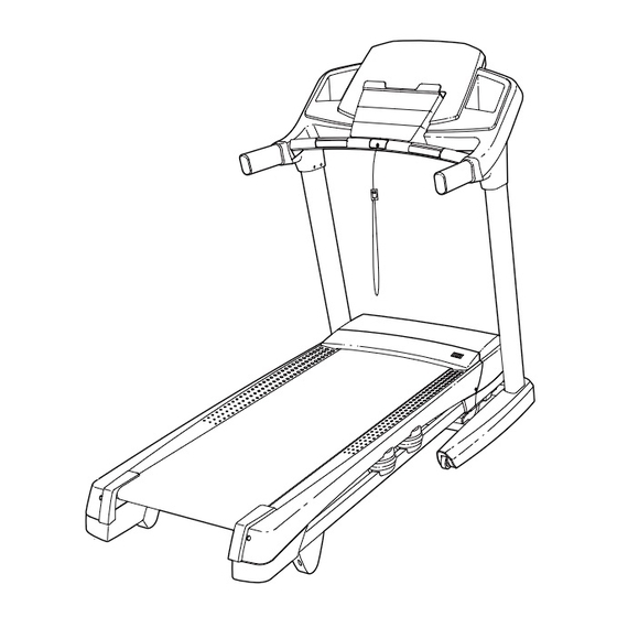
BEFORE YOU BEGIN Thank you for selecting the revolutionary PROFORM reading this manual, please see the front cover of this ® 790 T treadmill. The 790 T treadmill offers an impres- manual. To help us assist you, please note the product sive selection of features designed to make your model number and serial number before contacting us. -
Page 6: Part Identification Chart
PART IDENTIFICATION CHART Use the drawings below to identify small parts used for assembly. The number in parentheses below each draw- ing is the key number of the part, from the PART LIST near the end of this manual. The number following the key number is the quantity used for assembly. -
Page 7: Assembly
ASSEMBLY •• To hire a service technician to assemble this prod- •• To identify small parts, see page 6. uct in your home, call 1-800-445-2480. •• Assembly requires the following tools: •• Assembly requires two persons. the included hex keys ••... - Page 8 3. Identify the Left Upright (89), which is marked ““Left.”” Have a second person hold the Left Upright near the Base (94). See the inset drawing. Tie the wire tie in the Left Upright (89) securely around the end of the Wire Upright Wire (81).
- Page 9 5. Identify the Left Base Cover (82) and the Right Base Cover (83). Slide the Left Base Cover onto the Left Upright (89). Slide the Right Base Cover onto the Right Upright (90). Do not press the Base Covers into place yet. Identify the Left Upright Cover (79) and the Right Upright Cover (80).
- Page 10 7. Attach the Left Handrail (88) to the Left Upright (89) with two 5/16" x 1" Screws (5), two 5/16" Star Washers (11), and a 5/16" x 1 1/4" Bolt (4). Do not fully tighten the Screws and Bolt yet. Attach the Right Handrail (87) in the same way.
- Page 11 10. With the help of a second person, hold the con- sole assembly near the Left Handrail (88). Connect the Upright Wire (81) to the console Console wire. See the inset drawing. The connectors Assembly should slide together easily and snap into place.
- Page 12 12. Firmly tighten the four the 3/8" x 2 3/4" Screws (7) and the four 3/8" x 1 1/4" Screws (8) (only one side is shown). Press the Left Base Cover (82) and the Right Base Cover (83) onto the Base (94) until they snap into place.
- Page 13 15. Attach the Left Tray (107) and the Right Tray (108) to the console assembly with four #8 x 1/2" Screws (1). Console Assembly 16. IMPORTANT: See page 15 and plug in the power cord. Next, see page 17 and turn on IMPORTANT: the power.
- Page 14 17. IMPORTANT: Before you begin this step, make sure that you have read and followed all the instructions in step 16. Raise the Frame (56) to the position shown. Have a second person hold the Frame until step 18 is completed. Orient the Storage Latch (53) so that the large barrel and the latch knob are oriented as shown.
-
Page 15: Operation And Adjustment
OPERATION AND ADJUSTMENT HOW TO CONNECT THE POWER CORD nominal 120-volt circuit capable of carrying 15 or more amps. To avoid overloading the circuit, do Use a Surge Suppressor not plug other electrical devices, except for low- power devices such as cell phone chargers, into Your treadmill, like other electronic equipment, can be the surge suppressor or into an outlet on the same damaged by sudden voltage changes in your home’’s... - Page 16 CONSOLE DIAGRAM FEATURES OF THE CONSOLE You can even listen to your favorite workout music or audio books with the console’’s stereo sound system The treadmill console offers an impressive array of while you exercise. features designed to make your workouts more effec- tive and enjoyable.
-
Page 17: To Turn On Power
HOW TO TURN ON THE POWER HOW TO USE THE MANUAL MODE IMPORTANT: If the treadmill has been exposed to 1. Insert the key into the console. cold temperatures, allow it to warm to room tem- perature before turning on the power. If you do not See HOW TO TURN ON THE POWER at the left. - Page 18 4. Change the incline of the treadmill as desired. The My Trail tab will show a track that represents 1/4 mile (400 m). As you exercise, the black rect- To change the incline of the treadmill, press the angle will show your progress. The My Trail tab will Incline increase or decrease button or one of the also show the number of laps you complete.
- Page 19 6. Measure your heart rate if desired. 7. When you are nished exercising, remove the key from the console. Before using the hand- Step onto the foot rails, press the Stop button, and grip heart adjust the incline of the treadmill to the lowest rate monitor, setting.
-
Page 20: How To Use Onboard Workout
HOW TO USE AN ONBOARD WORKOUT to ash. If a different speed and/or incline setting is programmed for the next segment, the new speed 1. Insert the key into the console. and/or incline settings will appear in the display for a few seconds and the treadmill will automatically See HOW TO TURN ON THE POWER on page 17. - Page 21 HOW TO USE AN IFIT LIVE WORKOUT calories you will burn, and the name of the workout. If you select a competition workout, the display will Note: To use an iFit Live workout, you must have an count down to the beginning of the race. optional iFit Live module.
- Page 22 THE INFORMATION MODE 3. CONTRAST LVL: Press the Incline increase and decrease buttons to adjust the contrast level of the The console features an information mode that keeps display. track of treadmill information and allows you to person- alize console settings. If a module is connected, you may also select the following screen: To select the information mode, hold down the Stop...
- Page 23 HOW TO USE THE STEREO SOUND SYSTEM Next, press the play button Decrease on your MP3 player, CD To play music or audio books through the console’’s player, or other personal stereo speakers, you must connect your MP3 player, audio player. Adjust the vol- CD player, or other personal audio player to the con- ume on your personal audio sole through the audio jack.
-
Page 24: How To Fold And Move The Treadmill
HOW TO FOLD AND MOVE THE TREADMILL HOW TO FOLD THE TREADMILL HOW TO MOVE THE TREADMILL To avoid damaging the treadmill, adjust the incline Before moving the treadmill, fold it as described at the to the lowest position before you fold the treadmill. left. -
Page 25: Troubleshooting
TROUBLESHOOTING Most treadmill problems can be solved by following c. Remove the key from the console, and then the simple steps below. Find the symptom that reinsert it. applies, and follow the steps listed. If further assis- tance is needed, see the front cover of this manual. d. - Page 26 Locate the Reed Switch (52) and the Magnet (50) b. If the walking belt is overtightened, treadmill per- on the left side of the Pulley (49). Turn the Pulley formance may decrease and the walking belt may until the Magnet is aligned with the Reed Switch. become damaged.
- Page 27 SYMPTOM: The walking belt is off-center or slips b. If the walking belt slips when walked on, rst when walked on remove the key and UNPLUG THE POWER CORD. Using the hex key, turn both idler roller a. If the walking belt is off-center, rst remove the screws clockwise, 1/4 of a turn.
-
Page 28: Exercise Guidelines
EXERCISE GUIDELINES Burning Fat——To burn fat effectively, you must exer- WARNING: cise at a low intensity level for a sustained period of Before beginning this time. During the first few minutes of exercise, your or any exercise program, consult your physi- body uses carbohydrate calories for energy. - Page 29 SUGGESTED STRETCHES The correct form for several basic stretches is shown at the right. Move slowly as you stretch ——never bounce. 1. Toe Touch Stretch Stand with your knees bent slightly and slowly bend forward from your hips. Allow your back and shoulders to relax as you reach down toward your toes as far as possible.
-
Page 30: Part List
PART LIST Model No. PFTL81910.1 R0213A Key No. Qty. Description Key No. Qty. Description #8 x 1/2" Screw Reed Switch Clip #8 x 3/4" Screw Reed Switch 3/8" x 2" Bolt Storage Latch 5/16" x 1 1/4" Bolt Drive Motor 5/16"... - Page 31 Key No. Qty. Description Key No. Qty. Description Module Housing Right Tray Console Back Console Base Console Base Ground Wire Console Frame Hood Clip Ground Wire #10 x 3/4" Flat Head Screw Console Clamp 5/16" Flat Washer Left Tray –– User’’s Manual Note: Speci...
-
Page 32: Exploded Drawing
EXPLODED DRAWING A Model No. PFTL81910.1 R0213A... - Page 33 EXPLODED DRAWING B Model No. PFTL81910.1 R0213A...
- Page 34 EXPLODED DRAWING C Model No. PFTL81910.1 R0213A...
- Page 35 EXPLODED DRAWING D Model No. PFTL81910.1 R0213A...
-
Page 36: Ordering Replacement Parts
ORDERING REPLACEMENT PARTS To order replacement parts, please see the front cover of this manual. To help us assist you, be prepared to pro- vide the following information when contacting us: •• the model number and serial number of the product (see the front cover of this manual) ••...
Need help?
Do you have a question about the 790t Treadmill and is the answer not in the manual?
Questions and answers
how do you take apart
The manual does not provide specific instructions on how to take apart the Pro-Form 790t Treadmill. It does mention removing screws to access certain components and advises that servicing beyond the provided procedures should be performed by an authorized service representative. If disassembly is required, it is recommended to consult a professional.
This answer is automatically generated