Mitsubishi Electric XD490U User Manual
Srgb
Hide thumbs
Also See for XD490U:
- User manual (40 pages) ,
- Control manual (6 pages) ,
- Specifications (2 pages)

Related Manuals for Mitsubishi Electric XD490U


Summary of Contents for Mitsubishi Electric XD490U
- Page 1 DLP™ PROJECTOR MODEL XD490U XD460U User Manual XD490 XD460 This User Manual is important to you. Please read it before using your projector.
- Page 2 CAUTION RISK OF ELECTRIC SHOCK DO NOT OPEN CAUTION : TO REDUCE THE RISK OF ELECTRIC SHOCK, DO NOT REMOVE COVER (OR BACK) NO USER-SERVICEABLE PARTS INSIDE REFER SERVICING TO QUALIFIED SERVICE PERSONNEL. The lightning fl ash with arrowhead symbol within an equilateral triangle is intended to alert the user to the presence of uninsulated “dangerous voltage”...
-
Page 3: Table Of Contents
This symbol mark is according to the directive 2002/96/EC Article 10 Information for users and Annex IV. Your MITSUBISHI ELECTRIC product is designed and manufactured with high quality materials and components which can be recycled and reused. This symbol means that electrical and electronic equipment, at their end-of-life, should be disposed of separately from your household waste. -
Page 4: Important Safeguards
Important safeguards Please read all these instructions regarding your 10. Power sources projector and retain them for future reference. Follow This projector should be operated only from the all warnings and instructions marked on the projector. type of power source indicated on the marking label. - Page 5 Do not touch the air outlet grille and WARNING: bottom plate, which become hot. Unplug immediately if there is something Do not touch them or put other equipment in front wrong with your projector. of the air outlet grille. The air outlet grille and bottom Do not operate if smoke, strange noise or odor comes plate, when heated, may cause injury or damage to out of your projector.
-
Page 6: Preparing Your Projector
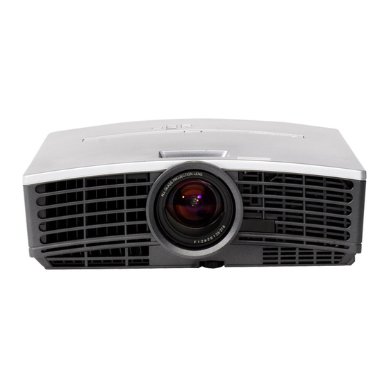
Preparing your projector Checking accessories The following accessories are provided with this projector. Check to be sure that all of the accessories are packed in the package. Cables Mini D-SUB Mini D-SUB 15-pin USB 4 -pin 9-pin (type B) Mini D-SUB 8-pin USB 4 -pin... - Page 7 Overview 1 FOCUS ring 2 ZOOM ring 3 Control panel 4 Air outlet grille 5 Remote control sensor (Front) 6 Air inlet grille 7 Air outlet grille 8 Terminal board 9 Kensington Security Lock Standard connector 10 Air inlet grille Control panel 1 POWER button 2 AUTO POSITION /...
- Page 8 Preparating your projector (continued) Bottom side 1 Adjustment foot (Front) 2 Lamp cover 3 Adjustment feet (Rear) Caution: Do not replace the lamp immediately after using the projector because the lamp would be extremely hot and it may cause burns. 1 Laser aperture Remote control 2 Transmission window...
-
Page 9: Using The Remote Control
Using the remote control Operational range of the remote control • Keep the remote control photo-sensor out of direct sunlight or fl uorescent lamp light. • Keep the remote control photo-sensor at least 2 m away from fl uorescent lamps. Otherwise, the re- Front of projector Rear of projector mote control may malfunction. -
Page 10: Setting Up Your Projector
Setting up your projector Setting up the screen Install the screen perpendicularly to the projector. If the screen can not be installed in such a way, adjust the projection angle of the projector. (See below.) • Install the screen and projector so that the projector’s lens is placed at the same height and horizontal position of the screen center. - Page 11 Front projection, ceiling mounting Caution: For ceiling mounting, you need the ceiling mount kit de- • Placing the projector directly on a carpet impairs signed for this projector. Ask a specialist for installation. ventilation by the fans, causing damage or failure. For details, consult your dealer.
-
Page 12: Screen Size And Projection Distance
Setting up your projector (continued) Screen size and projection distance Refer to the following table to determine the screen size. Screen size Center of the lens (Width of the projected image) Projected distance (L) When the aspect ratio of the screen is 4:3 Screen size Projected distance (L) 4:3 Diagonal size... -
Page 13: Viewing Computer Images
Viewing computer images A. Connecting the projector to a computer Preparation: • Make sure that the power of the projector and that of the computer are turned off. • When connecting the projector to a desktop computer, disconnect the RGB cable that is connected to the monitor. For analog connection: COMPUTER IN/ 1. - Page 14 Viewing computer images (continued) About DDC The COMPUTER/COMPONENT VIDEO IN-1 terminal of this projector complies with the DDC1/2B standard and the COMPUTER/COMPONENT VIDEO DVI-D (HDCP) terminal complies with the DDC2B standard. When a computer supporting this standard is connected to this terminal, the computer will automatically load the information from this projector and prepare for output of appropriate images.
- Page 15 C. Projecting images Preparation: • Remove the lens cap. • Turn on the power of the connected computer. FOCUS ring COMPUTER1, 2 buttons POWER button ZOOM ring DVI-D(HDCP) button POWER button POWER STATUS AUTO POSITION COMPUTER KEYSTONE VIDEO COMPUTER button ENTER VOLUME MENU...
- Page 16 Viewing computer images (continued) POWER button POWER button POWER STATUS AUTO POSITION COMPUTER KEYSTONE VIDEO ENTER VOLUME MENU To stop projecting: 8. Press the POWER button. • A confi rmation message is displayed. • To cancel the procedure, leave the projector for a while or press the MENU button. 9.
-
Page 17: Viewing Video Images
Viewing video images A. Connecting the projector to video equipment Preparation: • Make sure that the power of the projector and that of the video equipment are turned off. Connecting to a video player, etc. Video player, or the like 1. - Page 18 Viewing video images (continued) Projector + DVD player or HDTV decoder Some DVD players have an output connector for 3-line fi tting (Y, C ). When connecting such DVD player with this projector, use the COMPUTER/COMPONENT VIDEO IN-1 or 2 terminal. Mini D-SUB 15 pin-BNC Comversion cable (Option) HD/CS...
- Page 19 C. Projecting images Preparation: • Remove the lens cap. • Turn on the power of the connected video equipment. FOCUS ring ZOOM ring COMPUTER1, 2 button POWER button S-VIDEO button DVI-D(HDCP) button VIDEO button POWER button POWER STATUS AUTO POSITION COMPUTER KEYSTONE VIDEO...
- Page 20 Viewing video images (continued) POWER button POWER button POWER STATUS AUTO POSITION COMPUTER KEYSTONE VIDEO ENTER VOLUME MENU To stop projecting: 8. Press the POWER button. • A confi rmation message is displayed. • To cancel the procedure, leave the projector for a while or press the MENU button. 9.
- Page 21 Setting the aspect ratio You can change the aspect ratio of the input video signal (or the ratio of width to height of the image). Change the setting according to the type of the input video signal. How to change the settings: With the remote control: 1.
-
Page 22: Menu Operation
Menu operation • Menus are not displayed when no signal is supplied to the projector. IMAGE COLOR ENHANCER AUTO PRESENTATION STANDARD THEATER sRGB GAMMA MODE DYNAMIC, NATURAL, DETAIL USER BrilliantColor 0 - 10 CONTRAST ±30 CONTRAST R ±30 BRIGHTNESS ±30 CONTRAST G ±30 COLOR TEMP . - Page 23 Available settings in the menus Set the following items on their relevant menus. 1. IMAGE menu 2. INSTALLATION menu 3. FEATURE menu 4. SIGNAL menu opt. opt. opt. opt. XGA60 XGA60 XGA60 XGA60 INSTALLATION IMAGE FEATURE SIGNAL COLOR AUTO WALL SCREEN BEIGE ASPECT AUTO...
- Page 24 Menu operation (continued) 3. FEATURE menu ITEM SETTING FUNCTION ASPECT AUTO Select to change the aspect ratio automatically depending on the input signal. (Select this option for normal use.) 16:9 This option allows you to select the display position of squeezed (or horizontally compressed) images stored on DVD discs.
-
Page 25: Adjusting Projected Images
Adjusting projected images To adjust the brightness (CONTRAST and BRIGHTNESS): You can make adjustments for the brightness of the projected image using the menu. (See page 22 for menu setting.) 1. Display the IMAGE menu. 2. Select CONTRAST or BRIGHTNESS by pressing the button. - Page 26 Adjusting projected images (continued) To adjust the tone of white (COLOR TEMP.): You can select a preset color temperature (white tone) using the menu. (See page 22 for menu setting.) 1. Display the IMAGE menu. 2. Select COLOR TEMP. by pressing the button.
- Page 27 This projector automatically and properly projects video signals supplied from the computer. However, some video signals may not be projected, depending on the type of the computer. In such a case, press the AUTO POSITION button. (See page 16.) When the signal is still not projected properly, adjust the projected image using the SIGNAL menu.
-
Page 28: Advanced Features
Advanced features Password function 10. Select OK, and press the ENTER button. • If the entered passwords don’t match, an error This projector is equipped with the password function message will appear. that is designed for prevention of wrong operation by •... - Page 29 Expand • The size of the sub image varies depending on the input signal and settings. By pressing the EXPAND button on the remote control, • The PinP mode is unavailable while the VIRTUAL you can magnify the image to view the details. LENS SHIFT is in use.
- Page 30 Advanced features (continued) Mouse remote control By connecting to personal computer through the USB port, you can operate your computer with the projector remote control. Projector + computer with USB connector to USB port USB cable USB 4-pin USB 4-pin (type A) (type B) •...
-
Page 31: Replacing The Lamp
Replacing the lamp This projector is equipped with a lamp to project images. This lamp is a consumable. It may burn out or its brightness may decrease during use. In such cases, replace the lamp with a new one as soon as possible. Be sure to replace the lamp with a new lamp separately sold that is exclusive to this projector. -
Page 32: Cleaning
Replacing the lamp (continued) To replace the lamp: 1. Reverse the projector gently. 2. Loosen the screw (a) using a Phillips screwdriver (+), and remove the lamp cover (b). 3. Loosen the screws (c) using a Phillips screwdriver (+). 4. Pull up the handle. 5. -
Page 33: Troubleshooting
Troubleshooting Before asking for repair of the projector, check the following. If the symptom persists, stop using the projector, be sure to unplug the power plug, and then contact your dealer. No image appears on the screen. Problem Solution Power can not be •... - Page 34 Troubleshooting (continued) No image appears on the screen. (continued) Problem Solution "NO SIGNAL" is • Turn on the power of the connected device, or check whether there is something wrong with the connected device. displayed. • Check whether the external device output signals. (Check this especially when the external device is a notebook computer.) •...
- Page 35 Others Problem Solution The exhaust vents • This air comes out after cooling the inside of the projector. You may feel hot, but this is not a malfunction. emit warm air. • Check that the volume isn't set to low. No audio is output.
-
Page 36: Indicators
Indicators This projector has 2 indicators, each of which shows the operation condition of the projector. The following offer solutions to possible problems. If these problems persist, turn the projector off and consult your dealer. POWER indicator STATUS indicator Normal condition POWER STATUS CONDITION... -
Page 37: Specifi Cations
Specifi cations The specifi cations and outside appearance of the projector are subject to change without prior notice. DLP™ projector Type XD490U/XD460U Model 0.7-inch Single chip DMD Display Technology Pixel 1024 x 768 = 786432 pixels F 2.4 - 2.6 f= 23 - 27.6 mm... - Page 38 Specifi cations (continued) Specifi cation of RGB signals in each computer mode of the projector Signal mode resolution horizontal Vertical Normal mode Real mode (H x V) frequency (kHz) frequency (Hz) (H x V) (H x V) TV60, 480i(525i) 15.73 59.94 1024 x 768 *1, *3...
- Page 39 DVI-D (HDCP) Connectors COMPUTER IN / COMPONENT VIDEO IN (DVI-D 24-pin) (Mini D-SUB 15-pin) SERIAL (8-pin) Pin No. Spec. R(RED)/C G(GREEN)/Y PIN No. SPEC PIN No. SPEC B(BLUE)/C DATA 2- DATA 2+ +5V Power DATA 2 Shield Ground Hot Plug Detect Pin No.
- Page 40 Technical Inquiries :+886-2-2833-9813 Centro Direzionale Colleoni, Palazzo Persero-Ingresso 2, Phone :+852-2422-0161 Via Paracelso 12, 20041 Agrate Brianza, Italy MKY (Mitsubishi Electric Kang Yong Watana Co., Ltd. ) :+852-2487-0181 Sales & Technical Inquiries http://www.mitsubishi-kyw.co.th/ SINGAPORE (Mitsubishi Electric Asia Pte. Ltd.) Phone...
Need help?
Do you have a question about the XD490U and is the answer not in the manual?
Questions and answers