Table of Contents
Advertisement
Quick Links
Advertisement
Table of Contents

Related Manuals for Rokonet ORBiT-14


Summary of Contents for Rokonet ORBiT-14
- Page 1 User’s Manual...
- Page 2 No part of its contents may be used for any other purpose, disclosed to any person or firm or reproduced by any means, electronic or mechanical, without the express prior written permission of Rokonet Electronics Ltd. The text and graphics are for the purpose of illustration and reference only.
- Page 3 If trouble is experienced with the Alarm Control Panel for repair or warranty information please contact: Rokonet Industries USA Inc 2822 NW 79th Ave. Miami, Florida 33122 USA, phone number 305 592 3820, URL: sales@rokonetusa.com.
- Page 4 Consult the dealer or an experienced Radio/TV technician for help. Changes or Modifications (Ref.: FCC Part 15, Para. 15.21 and 15.27) Changes or modifications to this unit not expressly approved by Rokonet, Ltd., could void the user's authority to operate the equipment.
- Page 5 Summary of User’s Commands Function Procedure System Arming [User Code] + [Arm] Group Arming [User Code] + [Stay] + [Group Number:: 1/2/3 / 0=All Groups] System Disarming [User Code] Duress Disarming [Duress Code] Silencing an Alarm [User Code] Bypassing / ] + [ 1 ] + [User Code ] + [ 2 digit zone number to be Unbypassing a Zone bypassed / unbypassed]...
- Page 6 User's Manual...
-
Page 7: Table Of Contents
Table of Contents Section 1: Getting Acquainted Introduction Terms and Definitions Section 2: Your Keypad Visual Indicators Power LED Arm LED Ready LED Fire LED Zone LED KEYS Emergency Keys Section 3: User Codes Setting/Changing the User Codes Deleting User Codes Setting User Authority Levels Section 4: Arming and Disarming the System Arming... - Page 8 Section 5: Zone Bypassing Code Bypassing Quick Bypass Determining Which Zone Is Bypassed Section 6: User Functions Section 7: System Troubles Section 8: System Sounds viii User's Manual...
-
Page 9: Section 1: Getting Acquainted
Introduction Congratulations on your purchase of Rokonet’s ORBIT-14 Security System. The ORBIT-14 has been specifically designed to meet a wide range of security needs for many residential and small commercial applications. You communicate with your ORBIT-14 through its keypad(s). Using its keys, you can issue commands to your system. -
Page 10: Terms And Definitions
"lower" authority level are more restricted in what they may do. There are five different Authority Levels available for users of the ORBIT-14, as described on page 12. - Page 11 Central Station any troubles or malfunctions it senses, so that a service call can be made. User Code: A four-digit code that is used to perform many of the ORBIT-14 functions. Utility Output (UO): A household appliance. In addition to your system's...
-
Page 12: Section 2: Your Keypad
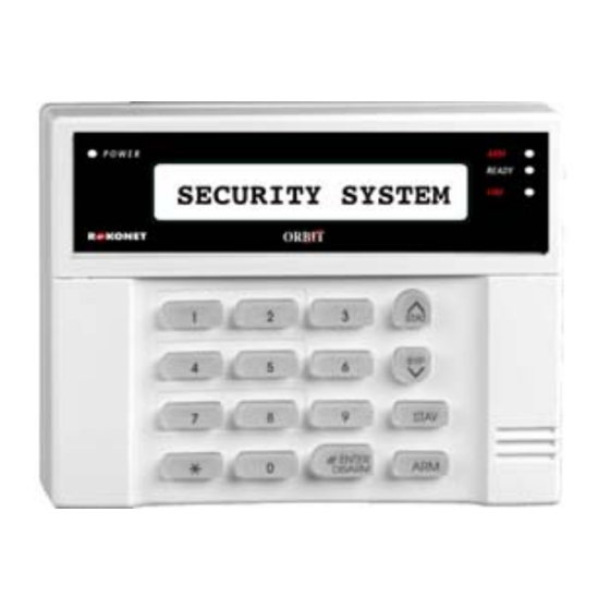
Section 2: Your Keypad The ORBIT-14 can support up to 5 keypads, with a choice of four styles: LCD, 6 LEDs, 8 LEDs or 14 LEDs. This manual discusses the operation of the ORBIT-14 from the LED keypads. This section discusses the keypad’s visual indicators and the use of its keys. -
Page 13: Power Led
Power LED The Power LED indicates the status of system operation. CONDITION DESCRIPTION The system is operating properly from commercial (AC) power; its backup battery is in good condition. The system is inoperative due to lack of power (from both commercial AC and backup battery);... -
Page 14: Fire Led
Fire LED The Fire LED is an indicator of a fire alarm in the system. CONDITION EXPLANATION A fire alarm or fire emergency is in progress or has recently occurred. All fire zones are operating normally . FLASHING A fault has been detected in the system's fire zone and needs to be corrected;... -
Page 15: Emergency Keys
Keys Function The [ ] key is used to enter the User Functions mode (see page 21). Used to arm the system's intrusion detectors to the "AWAY" mode; it may be necessary to enter a numeric User Code before pressing the Arm key. Refer to page 14 for additional information. - Page 16 User's Manual...
-
Page 17: Section 3: User Codes
User Code (as discussed on page 9). Your ORBIT-14 permits up to 20 User Codes. One of the codes is considered the Master Code; the individual(s) using the Master Code is given the following special privileges:... - Page 18 STEP DESCRIPTION Enter a 2-digit user code. Example: To change the Master Code, press "00": To enter/change the User Code 1, press "01": To enter/change the User Code 12, press "12": It is possible to enter/change up to 20 User Codes. Enter the new 4-digit code selected for the Master Code or for the User Code of your choice: If successful, the keypad will emit a one-second confirming...
-
Page 19: Deleting User Codes
Deleting User Codes At times, it may be desirable to completely delete a User Code. Note that it is impossible to delete the Master Code (although it can be changed). NOTE: The system must be disarmed in order to set or change user codes. The ARM LED will be OFF. -
Page 20: Setting User Authority Levels
Authority Level. Those with a "higher authority" have access to a greater number of system functions, while those with a "lower authority" are more restricted in what they may do. There are five different Authority Levels available for users of the ORBIT-14, as described below: LEVEL DESCRIPTION... - Page 21 STEP DESCRIPTION Enter the 2-digit user number. For example: To set authority level for user 1 press "01". Enter 1digit for the user authority level as follows: 0: User 1: User Un - Bypass 2: Cleaner 3: Service For example, to enter/change User’s authority level to Service, press "3": NOTE: You can change the authority level for 19 users.
-
Page 22: Section 4: Arming And Disarming The System
Section 4: Arming and Disarming the System Arming Arming your system enables its intrusion detectors to trigger an alarm when violated. Remember, fire protection and the protection offered by the keypad's emergency keys are always armed and always available. If your system is equipped with environmental protection (for example, gas and/or water level detection) it is always available too. -
Page 23: Group Arming
Group Arming Group arming enables you to arm a number of zones using the key. Ask your installer about defining groups. STEP DESCRIPTION Check the READY LED on your keypad. If it is lit or flashing, the system is READY to be armed. If it is NOT lit or flashing, the system is NOT ready to be armed. -
Page 24: Determining Which Group Is Armed
Determining Which Group is Armed The system must be armed. To identify the armed group(s) STEP DESCRIPTION Enter your 4-digit User Code followed by NOTE: If your system is defined with Quick Arming simply press the The keypad’s first 3 Zone LED(s) corresponding to the armed group(s) will light for several seconds. -
Page 25: Keyswitch Arming
Keyswitch Arming If your system is equipped with a special keyswitch, it can, with the twist of a key, be toggled through Arm (Away) and Disarm modes. Disarming Disarming the System Disarming your system deactivates its detectors. Remember, fire protection and the protection offered by the keypad's emergency keys are always armed and always available. -
Page 26: Duress Disarming
IMPORTANT If the alarm was caused by a tripped Smoke Detector(s), the keypad's FIRE LED will remain lit, providing an indication that the fire system must be reset before it will be capable of detecting subsequent alarms. Furthermore, until reset, you will be prevented from arming your system. -
Page 27: Section 5: Zone Bypassing
Section 5: Zone Bypassing When an intrusion zone is not secured, the READY LED on your keypad will not light, nor can the system be readily armed. Noting which LED(S) are flashing in the keypad’s ZONES area can identify the faulted intrusion zone. Bypassing a zone enables you to arm the system even if a zone is open/not secured. -
Page 28: Determining Which Zone Is Bypassed
An additional zone(s) can be bypassed at the same time by adding its number to the sequence. For example, to bypass Zones 05, 07 and 12, press: [ 0 ] for 2 seconds + [ 5 ], [0] [7] [1] [2]. NOTES: Only the first digit of the first zone should be pressed for 2 seconds. -
Page 29: Section 6: User Functions
Section 6: User Functions Your ORBIT-14 comes with a variety of selectable User Functions. By entering the User Functions mode, a number of options become available which determine how your alarm system operates, such as: Adding, modifying, and deleting User Codes Bypassing zones Displaying a "memory"... - Page 30 USER DESCRIPTION PRESS COMMENTS FUNCTION Refer to Reset a Resets a Smoke System Troubles Smoke Detector + USER CODE on page 26, and Detector consult your Alarm Company or Installer. (Utility Output number responsible for resetting the Smoke Detector(s)) Refer to Display Displays system System Troubles...
- Page 31 USER DESCRIPTION PRESS COMMENTS FUNCTION For more on Set User Sets the user authority levels, Authority Level authority level + MASTER CODE see page 12. (2 digit user code) (New authority level code; 0= User; 1= User Un- bypass; 2= Cleaner; 3= Service) Enter the date in Setting the...
- Page 32 USER DESCRIPTION PRESS COMMENTS FUNCTION Set Follow-Me Sets the first You can include Phone Number phone number the special 1- 4 for the Follow- functions me function (up described in the to 32 digits) table below, as required. + MASTER CODE + Phone Number + [#] Function...
- Page 33 USER DESCRIPTION PRESS COMMENTS FUNCTION Event Logger Retrieves Use this option events located only with the LCD + MASTER CODE in the event keypad. A list of logger memory events are (up to 250 presented from the events). last entered to the first registered.
-
Page 34: Section 7: System Troubles
If not remedied quickly, a trouble condition will likely compromise your system and prevent it from properly doing its job. The ORBIT-14 is designed to be as trouble-free as possible. In the event of a problem, the POWER LED will flash about once every second. If this happens, perform the sequence described below to determine the problem. - Page 35 Zone 3 Set the system's time has lost track of the LED On and date, see page 23. time and/or date. Communication The ORBIT-14 has Zone 4 Check that your Trouble failed in its attempts LED On telephone line is...
- Page 36 To disable the Fire Alarm: In certain cases, the keypad's FIRE LED may remain lit steadily, even though there is no alarm in progress and the system is disarmed. USER FUNCTION DESCRIPTION AND REMEDY After a fire alarm has occurred and been silenced, the keypad's red FIRE LED will remain lit steadily if a Smoke Detector (presumably the one which caused the alarm) remains tripped.
-
Page 37: Section 8: System Sounds
Section 8: System Sounds Besides the visual indications provided by your keypad(s), your system is designed to produce audible annunciation after certain events. Depending on the circumstance, such sounds may be made by your system's keypad(s) or its external sounder (e.g., a siren or bell). EVENT KEYPAD SOUND SIREN/... - Page 38 NOTES: 1. If selected during the installation, a brief "chirp" may be heard from the siren when the Exit Delay period expires. See page 2 for additional information. 2. Whether or not the Police Emergency alarm is enunciated by the external sounder is determined by the alarm company during your system's installation.
- Page 39 Emergency Evacuation Plans An emergency evacuation plan should be established and used during an actual fire alarm condition. The following steps are recommended by the National Fire Protection Association (NFPA) and can be used as a guide when establishing a similar plan for your circumstances. Draw a floor plan of your premises showing windows, doors, stairs, and rooftops, which can be used for escape.
- Page 40 Notes...
- Page 41 ROKONET LIMITED WARRANTY Rokonet Electronics, Ltd. and its subsidiaries and affiliates ("Seller") warrants its products to be free from defects in materials and workmanship under normal use for 12 months from the date of production. Because Seller does not install or connect the product and because the product may be...
- Page 42 Contacting Rokonet Rokonet Electronics Ltd. is committed to customer service and product support. You can contact us through our website (www.rokonet.com) or at the following telephone and fax numbers: Tel: +1 (305) 592-3820 Fax: +1 (305) 592-3825 United Kingdom Tel: +44 (1527) 576-765...
Need help?
Do you have a question about the ORBiT-14 and is the answer not in the manual?
Questions and answers