Table of Contents
Advertisement
Advertisement
Table of Contents

Related Manuals for Rokonet ORBIT-PRO RP296MUD


Summary of Contents for Rokonet ORBIT-PRO RP296MUD
- Page 1 RP296MUD User's Manual...
- Page 3 R P 2 9 6 M U D User’s Manual...
- Page 4 Connect the equipment into an outlet on a circuit different from that to which the receiver is connected. Consult the dealer or an experienced Radio/TV technician for help. Changes or modifications to this unit not expressly approved by Rokonet, Ltd., could void the user's authority to operate the equipment. p/n: 5IN296UMUL B...
- Page 5 EMERGENCY EVACUATION PLANS An emergency evacuation plan should be established and used during an actual fire alarm condition. The following steps are recommended by the National Fire Protection Association (NFPA) and can be used as a guide when establishing a similar plan for your circumstances. 1.
- Page 6 This User's Manual contains all the It is necessary to ARM your information needed to operate your system to obtain protection Rokonet ORBIT-PRO Security System from intrusion. and to get the most from it. This page, All other forms of...
-
Page 7: Table Of Contents
Table of Contents SECTION 1: LET’S GET ACQUAINTED.......... 1 ................. 1 NTRODUCTION ................2 EFINITIONS Zone ................... 2 24-Hour Zone ................2 Central Stations ................2 Chimes ..................2 Trouble Reporting............... 2 Utility Outputs ................2 Key-switch .................. 2 Arming Your System ..............2 Full Arming and Home Arming ........... - Page 8 ............... 16 URESS ISARMING ........16 ISARMING SING URESS SECTION 4: PARTITIONED SYSTEMS......... 17 ................17 NTRODUCTION ............17 RMING ULTIPLE ARTITIONS ..........18 ISARMING ULTIPLE ARTITIONS SECTION 5: SYSTEM SOUNDS ............ 19 SECTION 6: USER FUNCTIONS ........... 20 SECTION 7: SYSTEM TROUBLES..........23 user manual...
-
Page 9: Section 1: Let's Get Acquainted
Section 1: Let’s Get Acquainted INTRODUCTION Congratulations on your purchase of Rokonet’s ORBIT-PRO Security System. The ORBIT-PRO has been specifically designed to meet a wide range of security needs for many residential and LED KEYPAD commercial applications. You communicate with your ORBIT-PRO through its keypad(s). -
Page 10: Some Definitions
There are a few terms with which you should SOME DEFINITIONS become familiar. Knowing them will help you to better understand and use your system A single detector, or group of detectors, usually Zone relating to a certain area of the premises or type of protection. -
Page 11: Full Arming And Home Arming
Before you arm your system, all of its zones must Secured or either be secured or bypassed. Bypassed Your ORBIT-PRO offers two kinds of system Full Arming and arming. Full Arming prepares all of the system's Home Arming intrusion detectors to sound an alarm, if violated, Home Arming (or Stay Arming) allows individuals to remain inside and move about the premises even after the system is armed... -
Page 12: Section 2: Your Keypad
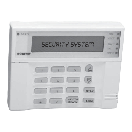
Section 2: Your Keypad As a user of your security system, you'll need to be VISUAL primarily concerned with the keypad. This section INDICATORS discusses the keypad's visual indicators and the use of its keys. Each keypad in your system reports its status via its LED (lighted) indicators at the right. -
Page 13: Ready Led
ARM LED CONDITION EXPLANATION The ARM LED The system's intrusion detectors are indicates whether or armed; subsequent violations of a not the system's protected point or area (e.g. a door, intrusion detectors a window, unauthorized motion) will are armed. result in a burglar alarm The intrusion function of the system is disarmed SLOW... -
Page 14: Fire Led
FIRE LED CONDITION EXPLANATION When lit, the FIRE LED A fire alarm or fire emergency is indicates that the progress recently system is experiencing occurred a fire alarm. When fire zones operating flashing, a problem has normally been detected on the fire circuit, and must be FLASHING A problem has been detected on... -
Page 15: Keys
The keys on the keypad can be used for a variety KEYS of functions. Each is explained below: Used to input the numeric codes which may be required arming, disarming, triggering emergency alarms, along with several other special functions NORMAL Used to enter the User Functions mode OPERATION USER... -
Page 16: Section 3: Operating Your System
Section 3: Operating Your System In this section, you'll learn how to perform most of the functions needed to properly operate your ORBIT-PRO and to get the most out of your security system. EMERGENCY KEYS Your keypad provides three sets of keys, which can be pushed at any time the police, fire department, or auxiliary assistance is required. -
Page 17: User Codes
USER CODES perform many ORBIT-PRO's functions, a security code (often called a User Code) must be entered at the keypad. Each individual using the system is assigned a AUTHORITY User Code, which, in turn, is linked to an Authority Level. Those with "higher... -
Page 18: Setting/Changing Access Codes
SETTING/CHANGING ACCESS CODES STEP DESCRIPTION The system must be disarmed). Enter the User Functions Mode ( ) and select Codes (5): Enter the 4-digit (or 6) Master (or higher authority) Code, and press [ ENTER] Enter the two digit User Index number 00 to 98 Note: the index number 00 belongs to the Grand Master Example: For User Code 6, press... -
Page 19: Deleting User Codes
DELETING USER CODES At times, it may be desirable to completely delete a User Code. Note that it is impossible to delete the Master Code (although it can be changed). STEP DESCRIPTION The system must be disarmed. Enter the User Functions Mode ( ) and choose Codes (5): Enter the current Master Code and press [ ENTER]: To delete any other User Code, enter the User Code's index... -
Page 20: Arming Your System
ARMING YOUR SYSTEM STEP DESCRIPTION Check the READY LED on your keypad. If lit or flashing, the system is READY. If NOT lit or flashing, the system is NOT ready to be armed. Secure or bypass the violated zone(s) and then proceed. Choose among one of the following arming types: Arming when Leaving the Premises Empty: Enter your User Code and press [ARM] key... -
Page 21: Zone Bypassing
When an intrusion zone is not secured, the ZONE BYPASSING keypad's READY LED will not light nor can the Warning : A bypassed system be readily armed. It may be convenient to zone may reduce the have one (or more) of the zones in your installation system's security bypassed–and thus ignored by your system. -
Page 22: View (Not Ready Zone Status)
VIEW (NOT READY ZONE STATUS) If the system is not ready to arm, there is at least one zone that is not secured. For LED Keypad the numbers corresponding to any unsecured zone will be illuminated and flashing on the LED ZONES area. For LCD Keypad, proceed with the following: STEP DESCRIPTION... - Page 23 DISARMING AN ARMED SYSTEM AND/OR SILENCING AN ALARM STEP DESCRIPTION If outside the premises, open an "entry" door. The keypad(s) will beep—indicating that the Entry Delay period has begun. Disarming an armed system Before the Entry Delay expires, Enter your User Code and press NOTE: If you make a mistake when entering your User Code, the keypad will produce three short beeps.
-
Page 24: Duress Disarming
If you are ever coerced into disarming your DURESS DISARMING system, you can comply with the intruder's wishes while sending a silent, duress alarm to the Central Station. To do so, you must use a special Duress Code. Which when used, will disarm the system in the regular manner, while simultaneously transmitting the duress alarm. -
Page 25: Section 4: Partitioned Systems
Section 4: Partitioned Systems INTRODUCTION The ORBIT-Pro system can be divided into partitions. Each partition may be viewed as a separate security system, each one can be armed and disarmed separately regardless the condition of the other. Partitions can be armed/disarmed one at a time, or all at once. Keypads and Partitions - Each keypad is assigned to different partition(s). -
Page 26: Disarming Multiple Partitions
DISARMING MULTIPLE PARTITIONS STEP DESCRIPTION Enter your User Code and press [ENTER/DISARM] Select the partition number (1-8) To disarm all partitions at once select “0” For LCD Keypad scroll with the or the keys to the desired partition (or enter the partition's number). The first item in the list will be ALL (partition number 0). -
Page 27: Section 5: System Sounds
Section 5: System Sounds Besides the visual indications provided by your keypad(s), your system is designed to produce audible annunciation after certain events. Depending on the circumstance, such sounds may be made by your system's keypad(s), its external sounder (e.g. a siren or bell), SIREN/ EVENT KEYPAD SOUND... -
Page 28: Section 6: User Functions
Section 6: User Functions Your ORBIT-PRO comes with a variety of selectable User Functions. By entering the User Functions mode, a number of options become available, To enter User Functions mode press [ ] followed by the Function index (see the table below) and user code. - Page 29 Quick Item Explanation Each time this function is enabled, your alarm company may subsequently gain a single remote access to your system to Enable U/D make any required programming changes. Contact your dealer for additional information. You may remove any customized message which, at the Del Rmt Msg * discretion of your alarm company, has been programmed to be displayed on all LCD Keypads.
- Page 30 For any function involving the Chime Feature, use to disable the Part. internal sounder for all keypads in the partition. Chime For any function involving the Chime Feature, use to enable the internal sounder for all keypads in the partition. Use to turn OFF a particular keypad's internal sounder during Local both Entry and Exit Delay periods and all fire and burglar alarms.
-
Page 31: Section 7: System Troubles
Section 7: System Troubles A rapid flashing of the POWER LED indicates a trouble condition. To view and identify the trouble, proceed as follows: For LCD KP - with the system disarmed, press and scroll the display till you reach 3) VIEW, press [ENTER]. - Page 32 once the TROUBLE: trouble has FALSE CODE P=1 If enabled by your been displayed dealer, your (LCD keypad False Code ZONE 5 LED system will only), it will NOTE: P=1 refers to Trouble WILL FLASH report, as a automatically the partition in which trouble, be removed the false code was...
- Page 33 Make sure the TROUBLE: connection of PS=1 AC TRBL this module's trafo to AC ZONE 10 LED power has not AC Loss in NOTE: Here, the WILL FLASH relates to optional been disturbed Power system is reporting Power Supply (requires the Supply that the first Power Make sure that...
- Page 34 Notes...
- Page 35 Copyright © 2005 Rokonet Electronics Ltd 14 Hachoma Street Rishon Letzion 75655 Israel All rights reserved. No part of this document may be reproduced in any form without prior written permission from the publisher.
- Page 36 Tel: +972 (0)3 9637777 Fax: 0044 161 655 5501 Fax. +972 (0)3 9616584 E-Mail: info@rokonet.co.uk E-mail: info@rokonet.co.il ITALY ROKONET ELECTRONICS S.R.L. Tel: (39) 023 925 354 Fax: (39) 023 925 131 E-Mail: info@rokonet.it © 2005 Rokonet Electronics Ltd 5IN296UMUL B 10/05...
Need help?
Do you have a question about the ORBIT-PRO RP296MUD and is the answer not in the manual?
Questions and answers