Table of Contents
Advertisement
Advertisement
Table of Contents

Related Manuals for Rokonet Orbit-14

Summary of Contents for Rokonet Orbit-14
- Page 1 Installation Manual...
- Page 2 Important Notice This manual is delivered subject to the following conditions and restrictions: This manual contains proprietary information belonging to Rokonet Electronics Ltd. Such information is supplied solely for the purpose of assisting explicitly and properly authorized users of the system.
- Page 3 If trouble is experienced with the Alarm Control Panel, for repair or warranty information please contact Rokonet Industries USA Inc 2822 NW 79th Ave. Miami, Florida 33122 USA, phone number 305 592 3820, URL: sales@rokonetusa.com. If the equipment is causing harm to the telephone network, the telephone company may request to disconnect the equipment until the problem is resolved.
-
Page 4: Installation Manual
Consult the dealer or an experienced Radio/TV technician for help. CHANGES OR MODIFICATIONS (Ref.: FCC Part 15, Para. 15.21 and 15.27) Changes or modifications to this unit not expressly approved by Rokonet, Ltd., could void the user's authority to operate the equipment. - Page 5 CE Declaration of Conformity We, the undersigned, ROKONET ELECTRONICS LTD. RISHON LEZION, HACHOMA ST. 14 ISRAEL PHONE: (972) 3 9616555 FAX: (972) 3 9616584 Certify and declare under our sole responsibility that the following equipment: Brand Type Product Description Orbit -14...
- Page 6 Installation Manual...
-
Page 7: Table Of Contents
Keypad Connection Connecting the J3 SIG IN Connector (Signal in Voice Mail) Installer Programming The Keypad Restoring Factory Defaults to the ORBIT-14 Introduction to Programming Programming Your ORBIT-14 Viewing the Contents of a Location Locations Whose Contents Occupy More Than One Digit... - Page 8 Communicator Reporting Codes: Locations 062-168 Reporting Codes for Alarm Events Restore Codes Other Reporting Codes Trouble Reports and Restorals Appendix 1: Installer Programming Worksheet Appendix 2: Contact ID & SIA Report Codes for Orbit-14 Appendix 3: Summary of User’s Commands Installation Manual...
-
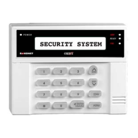
Page 9: Introduction To The Orbit-14
Introduction to the ORBIT-14 The ORBIT-14 is a fully featured security system, providing solutions for alerting and reporting premises alarm signals. The ORBIT-14 addresses the needs of many homes, offices, and small businesses. Its operation is designed around microprocessor and EEPROM (Electrically Erasable Programmable Read-Only Memory) technology, which stores the system’s operating... - Page 10 Periodic Testing • Daily test report to central station Optional Peripherals • Four relay-output expansion modules • Voice Module Event Log Event log of 250 events • Tamper Protection Box Tamper input (NC) • • Bell Tamper input (using 2.21 KΩ resistor) Keypad Tamper (Wall &...
-
Page 11: Technical Data
Technical Data Main Panel Input power 16.5 V AC 40 VA via transformer Rechargeable standby battery 12 V 7 A-Hours Auxiliary Power 12 V DC 600 mA maximum Bell/LS Sounder output 12 V DC 900 mA maximum Programmable outputs 1 X Relay output 3A 1 X Open collector Active pull down 500 mA maximum 1 X Open collector Active pull down 70 mA maximum Cabinet Dimensions:... - Page 12 Max. Run Length from Panel to Keypad Wire Ø (mm) Length Meter Feet Bell Loudspeaker Wiring Table (Distance in Feet) Ø mm Max. Feet Meter Feet Meter Feet Meter Feet Meter Current mA Detectors Distance in Feet Ø mm Max. Feet Meter Feet...
-
Page 13: Installation
Mounting the Control Panel 1. Mount the ORBIT-14’s metal cabinet at a protected dry location, near a source of unswitched AC Power, a good ground, and access to telephone service. Use the proper hardware (e.g., anchors, toggle bolts), as required, to insure a suitable mounting. -
Page 14: Wiring The Main Panel
• Do not short the terminals of the transformer together. This causes the internal fuse to blow. The transformer must be connected to a 230 VAC 24-hour outlet, which must be controlled by an approved over-current protection device. • The control is designed with reverse polarity protection on the battery charging circuit;... - Page 15 Grounding the Metal Box What Makes a Good Ground? Grounding provides a degree of protection against lightning and induced transients for any piece of electronic equipment that may, due to lightning or static discharge, experience permanent or general malfunctions. The ideal ground is considered to be a unified earth ground in which an 8-foot copper-clad rod, located close to the existing power and telephone ground rods, is sunk several feet into the earth.
-
Page 16: Telephone Line Connection
When connecting the ground wire, use a solid 14-gauge wire [or larger (numerically lower) size] connected between the ORBIT-14’s GND terminal and an acceptable electrical ground connection. Keep this wire as short as possible and do not run it in conduit, coil it, bend it sharply, or run it alongside other wiring. - Page 17 NOTES: For zones defined as EOL, use 2.21 KΩ resistors (supplied). By default all zones are defined as EOL termination. The Double End Of Line (DOEL) configuration allows a detector tamper switch, if violated, to register a tamper condition at the panel without the need for a separate connection to a designated tamper zone.
-
Page 18: Wiring Auxiliary Devices
Wiring Auxiliary Devices Use the Auxiliary Power AUX (+) COM (-) terminals to power PIRs, glass-break detectors (4-wire types), smoke detectors, audio switches, photoelectric systems and/or any device that requires a 12V DC power supply. NOTES: The total power from the AUX terminals should not exceed 600mA. To connect a 4-wire smoke detector or devices that require resetting after an alarm condition, connect the Auxiliary power AUX and UO terminals (refer to page 8 for smoke detector wiring). -
Page 19: Utility Output Connections
Utility Output Connections The ORBIT-14 main panel includes three Utility Outputs on board: 1 relay 3Amps, 1 500mA transistor and 1 open collector 70 mA transistor which can be used for switching an external device on or off or reset a “latched” smoke detector(s). Once the Utility Output (UO) is activated the device will be connected between AUX (+12V) and ground (0V). -
Page 20: Connecting The J4 Connector
Connecting the J4 Connector The J4 connector (jumper) determines the UO1 connection (behaviour), which is normally used for an external siren connection, as follows: • Positive (POS): When the J4 connector is placed on POS, the C terminal on UO1 receives 13.8V. -
Page 21: Keypad Connection
Keypad Connection The ORBIT-14 can support up to five keypads. Each keypad consists of five wires and three terminal blocks (for the connection of zones 7 and 8). NOTE: The three terminal blocks are not applicable in a 6-LED keypad. -
Page 22: Installer Programming
It is not necessary to enter data into all categories. Many locations have been factory- programmed with default parameters. NOTE: Power can be removed from the ORBIT-14, as its memory does not require a source of power to retain its information. Installation Manual... -
Page 23: Programming Your Orbit-14
Programming Methods Local Requirements LED or LCD keypads The keypad must be wired to the ORBIT-14 panel. Power must be applied to the ORBIT-14. ORBIT Programmer Easy programming of the control panel The programmer will be connected to parameters with... -
Page 24: Locations Whose Contents Occupy More Than One Digit
ZONE LEDs ZONE LEDs Digit Digit Example A: If Zone 4-ON, Zone 3-OFF, Zone 2-OFF, and Zone 1 ON, then the digit equals 9. Example B: If Zone 4-ON, Zone 3-OFF, Zone 2-ON, and Zone 1 - ON, then the digit equals 8. -
Page 25: Programming Time Out
To enter data into the location: Press data digits (0 - 9 digits including hexadecimal A-F) followed by #. Using your LED keypad, you can enter the hexadecimal digits A – F as follows: To Enter Press [STAY] + [1] [STAY] + [2] [STAY] + [3] [STAY] + [4]... - Page 26 Operation Action Comments Check the data •The first digit of the Press keys Displayed Zone Value stored in Location LEDs stored data is displayed. “008” •Observe the Zone LEDs. •Press [STAY] [STAY] to none digit 2, 1 advance to the next digit. •Once all four digits have digit none...
-
Page 27: Programming Locations
Disable the option of resetting the system to the factory defaults by using the default jumper. Location: 001 MS Lock: Def: 000000 MS Lock is a security function used in conjunction with Rokonet's Upload/Download software. It provides greater proprietary security when viewing Central Station parameters. -
Page 28: System Codes: Locations 006-010
NOTE: Use the “0” digit only to define account numbers with less than four digits. For example, for account number 123, enter 0123. In this case the ORBIT-14 will not send the “0” digit to the Central Station. To use an account number with “0” digit, for example “1207”, use the “A” digit instead of “0”... -
Page 29: System Time Definitions: Locations 011-016
Location: 008 Installer Code I Default: 0214 The installer code is a 4-digit code used by alarm company personnel authorized to modify the system’s parameters. It is recommended to change the “factory default” Installer Code to one of your own choice. Location: 009 Installer Code II Default: 1214... -
Page 30: Zone Types And Sounds: Locations 017-030
Enter the number of minutes (between 00 and 90). Periodic Test: Locations 015-016 The Periodic Test menu enables you to set the time period that the ORBIT-14 will automatically call the Central Station or Upload/Download phone numbers in order to check the phone line connection and the unit’s digital communicator. - Page 31 Locations: 017-030 Zone 1-14: (1 Digit): Zone Type Day Zone Usually assigned to an infrequently used door, such as an emergency door or a movable skylight. Used to alert the system user if a violation occurs during the disarmed period (trouble by day; burglary at night), as follows: •...
- Page 32 Locations: 017-030 Zone 1-14: (1 Digit): Zone Type Latch-Key-switch Zone – Delayed: This zone behaves similar to the Latched Key- switch Zone - Instant, described above, except that an exit delay will follow the arming of the system. Locations: 017-030 Zone 1-14: (2 Digit): Zone Sound Zone Sound and Comments...
-
Page 33: Zone Response Time & Group Masking: Locations 031-044
Zone Type and Sound Default Zone/s Location/s Type Sound Z3 – Z6 019 - 022 Z7-Z8 023 - 024 Z9 – Z14 025-030 Zone Response Time & Group Masking: Locations 031-044 Locations 031 through 044 are identical and are corresponding to zones 1 through 14. -
Page 34: Utility Outputs: Locations 046-051
(Default) Utility Outputs: Locations 046-051 The ORBIT-14 main panel includes three Utility Outputs (1 3Amps relay, 1 500 mA transistor and 1 open collector 70 mA transistor). These outputs help operate external devices in response to a number of system activities related to alarms, zones, any general system event or the actions of a particular user. - Page 35 Digit Event and Result Arm Follow (Pulse) UO is activated when the system is armed. The activation occurs after the expiration of the exit/delay period. The UO is activated for several seconds (pulse), after which is deactivated. Alarm Follow (Latched – Restore on Bell Time out) UO is immediately activated when the system goes into any type of alarm (i.e., intrusion, fire, keypad-initiated panic).
- Page 36 Digit Event and Result Zone 12 Alarm Follow (Pulsed) Zone 13 Alarm Follow (Latched) Zone 13Alarm Follow (Pulsed) Zone 14 Alarm Follow (Latched) Zone 14 Alarm Follow (Pulsed) Panic Follow (Latched) UO is activated immediately when a PANIC alarm is triggered by a violation of a zone, defined as Panic, or by pressing the keypad’s [1] and [2] keys simultaneously for two seconds.
- Page 37 [X] refers to the UO number in the circuit providing Smoke Detector power. If this is not done, it will be impossible to arm the panel. Please advise your customer of this contingency, as stated in the ORBIT-14’s User's Manual. Duress Code Follow (Latched) UO is activated when any duress code is entered.
-
Page 38: Communication Parameters: Locations 052-055
048 - 051 Communication Parameters: Locations 052-055 Locations 052 to 055 allow you to define the manner in which the ORBIT-14 communicates with the Central Station when it reports alarms, restorals, troubles, openings/closings, and tests. Locations 054 and 055 allow you define the communication format as defined by the Central Station (CS). - Page 39 In addition to reporting to the number when it is busy or The Upload/Download Central Station, the ORBIT-14 unresponsive. Applies to software at the alarm company has a Follow-Me feature, in both the MS Retries and FM calls the account.
-
Page 40: Dialler Control 2: Location 053
First digit: Not applicable, Always “0” • Second digit: Determines whether: 1. The ORBIT-14 is connected to a telephone and if the line is supervised. If the telephone line is cut for more than four minutes, supervision causes phone line trouble. - Page 41 Location: 054 Pulsed CS Protocols: (1 Digit): Digit Format Kissoff/Handshake Freq Message Validation Non-Extended 1400 Hz Dual Round Compare (Default) Non-Extended 2300 Hz Dual Round Compare Non-Extended 1400 Hz Parity Non-Extended 2300 Hz Parity Extended 1400 Hz Dual Round Compare Extended 2300 Hz Dual Round Compare...
-
Page 42: Automatic Central Station Protocols: Location 055
Format Name Kissoff/ Validation InterDigit Code (pulses Handshake Time Format /sec) Silent Knight/ 1400Hz Dual round ADEMCO Slow Silent Knight/ 1400Hz Dual round ADEMCO Slow Extended Radionics/DCI/ Franklin slow 2300 Hz Dual round Silent Knight Fast 1400 Hz Dual round Silent Knight Fast Extended 1400 Hz Dual round... -
Page 43: Upload/Download Rings: Location 056
Ademco 4/2 Express Upload/Download Rings: Location 056 Location 056 sets the number of rings that the ORBIT-14 will wait before automatically answering an incoming call. If such a call was initiated by the alarm company’s Upload/Download software, a process begins which allows a Remote Programming session to take place. -
Page 44: System Controls: Locations 059-060
System Controls: Locations 059-060 Locations 059-060 allow you to specify some additional parameters, which determine how the ORBIT-14 will operate. Location: 059 System Control 1 Default: 53 The location contains two digits: • First digit: Determines the digit corresponding to the choices involving Quick Arm / Quick Bypass / Bypass Enable / Loudspeaker / Bell-Siren. - Page 45 Location: 059 System Controls 1: (1st Digit): Digit Loudspeaker/Bell- Bypass Enable Quick Bypass Quick Arm Siren Bell-Siren Bell-Siren Bell-Siren Bell-Siren Bell-Siren Bell-Siren Default Bell-Siren Bell-Siren Loudspeaker Loudspeaker Loudspeaker Loudspeaker Loudspeaker Loudspeaker Loudspeaker Loudspeaker Location: 059 System Controls 1: (2nd Digit): Digit Voice Module UO Extender...
- Page 46 3 Minute Bypass IMQ Installation Czech installation UL installation Yes: All zones will Yes: Causes the following Yes: The ORBIT-14 Yes: The ORBIT-14 is be automatically parameters to function as is installed in installed in accordance bypassed for 3 follows:...
-
Page 47: Sub Installer Restriction Level: Location 061
Zone Restore Zone Restore Sub Installer Restriction Level: Location 061 The Sub Installer can be defined with two different authority levels. Each level restricts him from programming different locations in the ORBIT-14. Location: 061 Sub Installer Restriction Level Default: 01... -
Page 48: Communicator Reporting Codes: Locations 062-168
General tamper alarm (Box / Bell /Keypad) Restore Codes An ORBIT-14 Restoral Report informs the Central Station that the external sounder’s operation, initially triggered by the respective alarm condition, has either “timed out” or been silenced by the act of system disarming. Be sure to check with Central Station personnel if restorals are permitted and, if so, what codes are required. -
Page 49: Other Reporting Codes
Reporting Codes for Restore Alarm Events Location Description Digits Default Report Code Zone 1 Restoral Code Zone 2 Restoral Code Zone 3 Restoral Code Zone 4 Restoral Code Zone 5 Restoral Code Zone 6 Restoral Code Zone 7 Restoral Code Zone 8 Restoral Code Zone 9 Restoral Code Zone 10 Restoral Code... - Page 50 Location Description Digits Default Report Code User 9 arm Reporting code User 10 arm Reporting code User 11 arm Reporting code User 12 arm Reporting code User 13 arm Reporting code User 14 arm Reporting code User 15 arm Reporting code User 16 arm Reporting code User 17 arm Reporting code User 18 arm Reporting code...
-
Page 51: Trouble Reports And Restorals
Trouble Reports and Restorals Location Description Digits Default Report Code Low Battery Reporting code Loss of AC Power (for at least 15 min) Fire zone trouble Bell Loop Interrupted Clock not set Phone line cut Day zone trouble Low Battery restore Loss of AC Power restore Fire zone trouble Restore Bell Loop Restore... -
Page 52: Appendix 1: Installer Programming Worksheet
Appendix 1: Installer Programming Worksheet Customer _____________________________________ Central Station Account No: ___________ Address ______________________________________ Date of Installation: __________________ City _________________ State _________ Zip _______ Installer(s): ________________________ Customer Phone No: ( ) _________________________ Comments: ________________________ __________________________________ Comments: ___________________________________ Loca- Description Entry Loca- Description Entry... - Page 53 Loca- Description Entry Loca- Description Entry tion tion Tamper zone 6 / 14 User 16 arm Tamper Box / Bell / KP User 17 arm Zone 1 Restore User 18 arm Zone 2 Restore User 19 arm Zone 3 Restore Forced Arm Zone 4 Restore Level arming...
-
Page 54: Appendix 2: Contact Id & Sia Report Codes For Orbit-14
Appendix 2: Contact ID & SIA Report Codes for Orbit-14 Event Reporting Format Contact ID SIA (Level 1) Zones Alarms/Disarm Program Digit Code Program Digit Code Exit/Entry Alarm Exit/Entry Restore Burglary Zone Alarm Burglary Zone Restore 24 Hour Zone Alarm... - Page 55 Event Reporting Contact ID SIA (Level 1) Zones Alarms/Disarm Program Digit Code Program Digit Code Low Temperature Alarm/Restore Loss of Air Flow Special Special Emergency Key Alarm Special Emergency Key Restore Fire Zone Alarm Fire Zone Restore Fire Key Alarm Fire Key Restore Panic Key Alarm Panic Key Restore...
-
Page 56: Appendix 3: Summary Of User's Commands
Appendix 3: Summary of User’s Commands Function Procedure System Arming [User Code] + [Arm] Group Arming [User Code] + [Stay] + [Group #: 1,2, 3, 0=All Groups] System Disarming [User Code] Duress Disarming [Duress Code] Silencing an Alarm [User Code] Bypassing / Unbypassing a ] + [ 1 ] + [User Code ] + [ 2-digit zone number to be Zone... - Page 57 Notes...
- Page 58 Notes...
- Page 59 Rokonet Limited Warranty Rokonet Electronics, Ltd. and its subsidiaries and affiliates ("Seller") warrants its products to be free from defects in materials and workmanship under normal use for 12 months from the date of production. Because Seller does not install or...
- Page 60 Contacting Rokonet Rokonet Electronics Ltd. is committed to customer service and product support. You can contact us through our website (www.rokonet.com) or at the following telephone and fax numbers: Tel: +1 (305) 592-3820 Fax: +1 (305) 592-3825 United Kingdom Tel: +44 (1527) 576-765...
Need help?
Do you have a question about the Orbit-14 and is the answer not in the manual?
Questions and answers