Advertisement
Quick Links
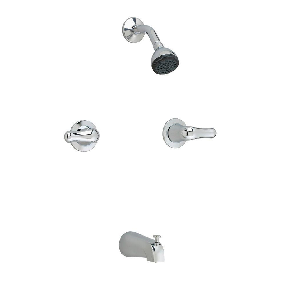
CADET
TWO-HANDLE BATH/SHOWER
CONJUNTO DE TINA/DUCHA DE 2 MANIJAS
ROBINETS DE BAIN/DOUCHE À 2 POIGNÉES
Thank you for selecting American-Standard...the benchmark of fine
quality for over 100 years. To ensure that your installation proceeds
smoothly--please read these instructions carefully before you begin.
Gracias por seleccionar los productos American Standard, sinónimo de la mejor
calidad durante más de 100 años. Por favor lea estas instrucciones detenidamente
antes de comenzar para que lleve a cabo la instalación sin contratiempos.
Nous vous remercions d'avoir choisi American Standard... synonyme de qualité supérieure
depuis plus de 100 ans. Pour vous assurer que l'installation se déroulera sans difficulté,
veuillez lire attentivement ces instructions avant de commencer.
ROUGHING-IN DIMENSIONS
DIMENSIONES CALCULADAS
1-1/4 DIA HOLE
DIMENSIONS
AGUJERO 1-1/4 DIAM.
PLOMBERIE BRUTE
TROU DIA. 1-1/4
1/2 N.P .T. SHOWER ARM
1/2 N.P .T. BRAZO DE DUCHA
BRAS DE DOUCHE 1/2 NPT
OPTIONAL TO FINISHED
FLOOR USUALLY
BETWEEN 65'' AND 78''
OPCIONAL PARA TERMINAR
PISO HABITUALMENTE
ENTRE 65'' Y 78''
OPTIONNEL : NIVEAU DÉFINITIF DU SOL,
HABITUELLEMENT ENTRE 165 ET
198 CM (65" - 78")
15/16"
15/16" (21.5 MM)
21.5 mm (15/16 po.)
1-3/4"
1-3/4" (44 MM)
44 mm (1-3/4 po.)
VALVE INLETS
1/2 C.W.T. OR
1/2 N.P .T.M.
ENTRADAS DE VÁLVULA
1/2 C.W.T. O
1/2 N.P .T.M.
SOUPAPES D'ENTRÉE
1/2 CWT OU 1/2 NPTM
1/2 N.P .T. SPOUT NIPPLE
1/2 N.P .T.
PICO BOQUILLA DE UNIÓN
MAMELON 1/2 NPT
BOTTOM OF TUB
FONDO DE LA BAÑERA
FOND DE BAIGNOIRE
1-1/4 DIA HOLE
AGUJERO 1-1/4 DIAM.
TROU DIA. 1-1/4
1
ROUGHING-IN FITTING
IMPORTANT: DO NOT REMOVE PLASTER GUARDS (2) UNTIL STEP 2.
Prepare water supplies per Roughing-in Dimensions.
Install VALVE (1) at indicated height and depth. Make sure the outlet marked "SHR" is pointing upward.
Apply Teflon Tape to threaded end of SUPPLY PIPE (6, 6a).
Install SUPPLY PIPES (6, 6a) into round end of UNION (7, 7a).
Hand tighten Hex End of UNION (7, 7a) onto valve inlet ports, then tighten with adjustable
wrench an aditional 1/2 turn. Secure VALVE BODY (1) to cross brace of wall structure.
Prepare SHOWER RISER (4) and ELBOW (3). Connect to TOP outlet, marked
"SHR" of VALVE BODY (1). (Plug "SHR" for Tub Filler installation only).
Prepare TUB FILLER PIPE (8), ELBOW (10) and roughing-in NIPPLE (9). Connect to
BOTTOM outlet of VALVE BODY (1). (Plug "Tub Outlet" for Shower installation only).
Add cross braces to wall structure and secure SHOWER RISER (4) and TUB FILER PIPE (8).
Cap (11) NIPPLE (9) and PLUG (5) ELBOW (3), with valves closed open supply lines
and check for leaks. Open both VALVES and check for leaks.
Close both valves and turn off water supplies. Finish wall construction.
AJUSTE CALCULADO
Cierre el abastecimiento de agua fría y caliente antes de comenzar.
IMPORTANTE: NO REMUEVA LAS PROTECCIONES DE YESO (2) HASTA EL PASO 2.
Prepare la instalación para agua de acuerdo con las dimensiones calculadas.
Instale la VÁLVULA (1) a la altura y profundidad indicadas. Asegúrese de que la salida marcada como "SHR" esté hacia arriba.
Aplicar cinta de Teflon a la tubería de la fuente
Instale las tuberías de la fuente (6, 6a) en el extremo redondo de la 'unión' (7, 7a)
Mano aprieta el extremo de la tuerca hexagonal de la 'unión' (7, 7a) sobre puer tos de la entrada de la válvula, entonces apriete con
llave ajustable una ∏ vuelta adicional
Asegure que el CUERPO DE LA VÁLVULA (1) cruce la plantilla de la estructura de la pared.
Prepare la TUBERÍA DE SUBIDA (4) y el CODO (3). Conecte a la salida SUPERIOR, marcada como
"SHR" en el CUERPO DE LA VÁLVULA (1). (Capór para instalacion de salida de tina).
Prepare la TUBERÍA DE LLENADO DE LA TINA (8), el CODO (10) y la BOQUILLA DE UNIÓN (9) calculada. Conecte a la salida INFERIOR del
CUERPO DE LA VÁLVULA (1).
Agregue las abrazaderas cruzadas a la estructura de la pared y asegure la TUBERÍA DE SUBIDA (4) y la TUBERÍA DE LLENADO DE LA TINA (8),
Tapa (11) BOQUILLA DE UNIÓN (9) y TAPÓN (5) CODO (3), con las válvulas cerradas abra las líneas de abastecimiento y busque pérdidas.
Abra ambas VÁLVULAS y busque pérdidas.
Cierre ambas válvulas y cierre el abastecimiento de agua. Termine la construcción en la pared.
Instrucciones de Instalacion
Instructions d'installation
FINISHED WALL
PARED TERMINADA
MUR FINI
1" MIN. 2" MAX.
1" MIN. 2" MAX.
2,54 CM MIN. 5,08 CM MAX.
3-5/8" REF.
3-5/8" REF.
RÉF. 3-5/8"
6-1/2 REF.
6-1/2 REF.
RÉF. 6-1/2"
(2) 1-3/4 DIA. HOLES
FOR VALVES ON 8" CENTERS
(2) AGUJEROS 1-3/4 DIAM.
PARA VÁLVULAS EN CENTROS DE 8"
(2) TROUS DIA. 1-3/4 POUR
ÉLÉMENT CENTRAL DE 20 CM
4-3/8 REF.
4-3/8 REF.
RÉF. 4-3/8
4"
4" (102 MM)
4-3/4 REF.
102 mm (4 po.)
4-3/4 REF.
DEL ANILLO DE TINA
RÉF. 4-3/4
HAUT - BORD DE
NOTE: NO CONCEALED PIPING FURNISHED
NOTA: CAÑERÍA ABIERTA ABASTECIDA
NOTA : NE COMPREND PAS LA TUYAUTERIE DISSIMULÉE
CAUTION
Turn off hot and cold water supplies before beginning.
Installation Instructions
CARE INSTRUCTIONS:
DO: SIMPLY RINSE THE PRODUCT CLEAN WITH CLEAR WATER. DRY WITH
A SOFT COTTON FLANNEL CLOTH.
DO NOT: DO NOT CLEAN THE PRODUCT WITH SOAPS, ACID, POLISH,
ABRASIVES, HARSH CLEANERS, OR A CLOTH WITH A COARSE SURFACE.
INSTRUCCIONES DE CUIDADO DEL PRODUCTO:
LIMPIE EL PRODUCTO CON AGUA LIMPIA Y SÉQUELO CON UNA TELA SUAVE
DE FRANELA DE ALGODÓN.
NO LIMPIE EL PRODUCTO CON JABÓN, ÁCIDOS, PULIDORES, ABRASIVOS,
LIMPIADORES FUERTES O TELAS ÁSPERAS.
INSTRUCTIONS POUR L'ENTRETIEN
FAIRE : SIMPLEMENT RINCER LE PRODUIT AVEC DE L'EAU CLAIRE JUSQU'À
CE QU'IL SOIT PROPRE SÉCHER AVEC UN LINGE DE FLANELLE DE COTON DOUX.
NE PAS FAIRE : NE PAS NETTOYER LE PRODUIT AVEC DES SAVONS, DE
L'ACIDE, DU POLISH, DES ABRASIFS, DES NETTOYANTS AGRESSIFS OU UN
LINGE À TEXTURE RUGUEUSE.
HOTLINE FOR HELP
Para información y respuestas a sus preguntas, llame sin costo al:
Pour information et réponses à vos questions, composer sans frais:
TOP OF TUB RIM
PARTE SUPERIOR
LA BAIGNOIRE
3275
Certified to comply with ANSI A112.18.1M U.S. PATENT NO. D269,696
Certificado para cumplir con ANSI A112.18.1M PATENTE U.S. Nº D269,696
Certifié conforme à la norme ANSI A 112.18. 1M Brevet É.-U. no D269,696
M 9 6 8 7 5 6 R e v 1 . 2
NUMBERO DE EMERGENCIA
ASSISTANCE TÉLÉPHONIQUE
For toll-free information and answers to your questions, call:
1 800 442-1902
Weekdays
Días laborales de las
8:00 to 6:00 p.m. EST
CANADA 1-800-387-0369 (TORONTO 1-905-306-1093)
Weekdays
Días laborales de las
8:00 to 6:00 p.m. EST
5
HOT
CALIENTE
CHAUD
2
7
1
6
8
11
Sur semaine:
Sur semaine:
3
4
CROSS
BRACE
CRUZAR
PLANTILLA
7a
6a
COLD
FRÍA
FROID
10
9
Advertisement

Related Manuals for American Standard 3275


Summary of Contents for American Standard 3275
-
Page 1: Installation Instructions
100 years. To ensure that your installation proceeds smoothly--please read these instructions carefully before you begin. Gracias por seleccionar los productos American Standard, sinónimo de la mejor calidad durante más de 100 años. Por favor lea estas instrucciones detenidamente antes de comenzar para que lleve a cabo la instalación sin contratiempos. - Page 2 RACCORD – PLOMBERIE BRUTE IMPORTANT: Lorsqu'on soude, enlever la PROTECTION CONTRE LE PLÂTRE, les CARTOUCHES et LES BUTÉES DE RETENUE (S'IL Y EN A). Lorsqu'on a fini de souder, rincer le corps du robinet, remettre les cartouches, les butées d'arrêt (s'il y en a) et la protection contre le plâtre avant de continuer l'installation. Utiliser un produit d'étanchéité pour filetage ou du ruban Téflon sur les connexions filetées. Préparer les conduits d’alimentation en eau selon les dimensions de la plomberie brute.
- Page 3 TEST INSTALLED FITTING Turn HANDLES to OFF position. Turn on water supplies and check for leaks. Operate both HANDLES to flush water lines thoroughly and check TUB SPOUT for leaks. Operate DIVERTER VALVE and check all SHOWER HEAD connections for leaks. SERVICE To change direction of handle rotation, proceed as follows:...
- Page 4 TORNILLO DE MANIJA VIS 027816-0070A PIPE PLUG 1/2-14 NPT TAPÓN 1/2-14 NPT BOUCHER 1/2-14 NPT CADET MODEL NUMBER NÚMERO DE MODELO NUMÉRO DE MODÈLE 3275 M962262-0070A DEEP ROUGH KIT JUEGO DE EXTENSIÓN TROUSSE EXTENSION M950010-0070A 1/2" FEMALE UNION UNIÓN HEMBRA1/2" RACCORD-UNION FEMELLE 1/2"...