
Related Manuals for VIA Technologies EPIA-TC


Summary of Contents for VIA Technologies EPIA-TC
- Page 1 User’s Manual EPIA-TC Mini-ITX Mainboard P/N: 99-51-012821-12 Version 1.20 December 11, 2004...
- Page 2 Copyright Copyright by VIA Technologies Inc. (“VIA”). No part of this manual may be reproduced or transmitted in any form without express written authorization from VIA. Trademarks All trademarks are the property of their respective holders. PS/2 is a registered trademark of IBM Corporation.
- Page 3 FCC-B Radio Frequency Interference Statement This equipment has been tested and found to comply with the limits for a class B digital device, pursuant to part 15 of the FCC rules. These limits are designed to provide reasonable protection against harmful interference when the equipment is operated in a commercial environment.
-
Page 4: Safety Instructions
Safety Instructions 1. Always read the safety instructions carefully. 2. Keep this User’s Manual for future reference. 3. Keep this equipment away from humidity. 4. Lay this equipment on a reliable flat surface before setting it up. 5. The openings on the enclosure are for air convection hence protects the equipment from overheating. -
Page 5: Box Contents
Box Contents • 1 x VIA Mainboard • 1 x User’s Manual • 1 x ATA-66/100/133 IDE Ribbon Cable • 1 x IDE Power Cable • 1 x Driver Utilities CD... -
Page 6: Table Of Contents
Table of Contents Chapter 1: Specifications ........1-1 Mainboard Specifications ............1-2 Mainboard Layout ..............1-4 Back Panel Ports ..............1-5 Slots ..................1-5 Onboard Connectors and Jumpers ...........1-6 Chapter 2: Installation..........2-1 CPU Installation ................2-2 Memory Module Installation ............2-4 Connecting the Power Supply...........2-6 Back Panel Ports ..............2-7 Connectors................2-10 Jumpers ..................2-17 Slots ..................2-18... - Page 7 Appendix A: Smart 5.1 ..........A-1 Intelligent 6-Channel Audio ............A-2 Appendix B: Add-on Modules ........ B-1 CCM-01..................B-2 LVDS-04 .................. B-4 RGB-01 ..................B-5 DVI-01 ..................B-6 Appendix C: Onboard Power Specifications ..C-1 DC-to-DC Specification ............C-2 Power Consumption (Board Only) ........... C-3 Power Consumption (With IDE) ..........
-
Page 8: Chapter 1: Specifications
The ultra-compact and highly intergrated VIA EPIA-TC Mini-ITX Mainboard is the smallest form factor mainboard specification available today, developed by VIA Technologies, Inc. as part of the company’s open industry-wide total connectivity initiative. The mainboard enables the creation of an exciting new generation of small, ergonomic, innovative and affordable embedded systems. -
Page 9: Mainboard Specifications
Chapter 1 Mainboard Specifications • VIA C3 / EDEN EBGA Processor (onboard) • Enhanced Ball Grid Array Package (EBGA) • Internal L1 128KB and L2 64KB cache memory Chipset • VIA CLE266 North Bridge • VT8235 South Bridge Memory • 1 x 200-pin DDR266 SODIMM socket (up to 1 GB) Expansion Slots •... -
Page 10: Form Factor
Specifications Back Panel I/O Ports • DC-in power jack • 1 x PS2 mouse port • 1 x PS2 keyboard port • 1 x VGA port • 1 x RJ-45 LAN port • 2 x USB 2.0/1.1 ports • 1 x Serial port •... -
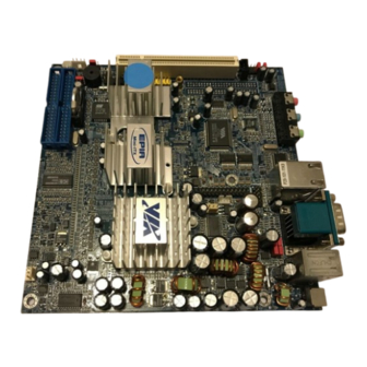
Page 11: Mainboard Layout
Chapter 1 Mainboard Layout Back Panel PS2_MS COM1 RJ45 DC-in PS2_KB VGA Out Line-Out Line-In Microphone... -
Page 12: Back Panel Ports
Specifications Back Panel Ports Port Description Page Audio Jacks Line-Out, Line-In, Microphone COM 1 Serial port DC-in Power Jack DC Power input PS2-KB PS2 keyboard port PS2-MS PS2 mouse port RJ45 10/100 NIC port USB 1-2 Universal Serial Bus ports 1 - 2 VGA Out VGA out port Slots... -
Page 13: Onboard Connectors And Jumpers
Chapter 1 Onboard Connectors and Jumpers Connecter/Jumper Description Page +12V_CONN +12V power connector 2-15 CLEAR_CMOS Jumper to reset CMOS settings to default 2-17 COM2 Second serial port connector 2-13 F_AUDIO Front audio connector 2-14 F_PANEL Case connectors 2-11 Fans CPU Fan, System Fan 2-14 C Header C header... -
Page 14: Chapter 2: Installation
Chapter Installation This chapter provides you with information about hardware setup procedures. While installing the mainboard, carefully hold the components and closely follow the installation procedures. Some components may be damaged if they are installed incorrectly. It is recommended to use a grounded wrist strap before handling computer components. - Page 15 Chapter 2 The VIA EPIA-TC Mini-ITX Mainboard includes an embedded VIA Eden Processor or VIA C3 E-Series Processor. The CPUFAN (CPU fan) and SYSFAN (system fan) run on +12V and maintain system cooling. When connecting the wire to the connectors, always be aware that the red wire is the Positive and should be connected to the +12V.
-
Page 16: The Via Eden Processor
Installation The VIA Eden Processor Providing ultra-low power consumption and advanced thermal dissipation properties, the VIA Eden Processor features a fanless design. The VIA Eden Processor requires only a heatsink as shown. Warning: This motherboard is not designed to support overclocking. Any attempt to operate beyond product specifications is not recommended. -
Page 17: Memory Module Installation
Chapter 2 Memory Module Installation The VIA EPIA-TC Mini-ITX Mainboard provides one SODIMM slot on the bottom-side of the board. It uses 200-pin DDR266 memory modules. Memory slot located on the bottom-side of the board. DDR SDRAM Module Installation Procedures 1. -
Page 18: Available Ddr Sdram Configurations
Installation Available DDR SDRAM Configurations Refer to the table below for available configurations on the mainboard Slot Memory Module Total Memory SODIMM 64MB, 128MB, 256MB, 512MB, 64 MB - 1 GB (Bank 0 & 1) Maximum System Memory Supported 64 MB - 1 GB... -
Page 19: Connecting The Power Supply
Chapter 2 Connecting the Power Supply The VIA EPIA-TC Mini-ITX Mainboard has an onboard DC-to-DC converter. It requires an AC adapter that has a 12V DC output. Always make sure that all components are installed correctly to ensure that no damage will be caused. -
Page 20: Back Panel Ports
Installation Back Panel Ports The back panel has the following ports: PS2_MS COM1 RJ45 DC-in PS2_KB VGA Out Line-Out Line-In Microphone Mouse Port: PS2_MS The mainboard provides a standard PS/2 mouse connector for attaching a PS/2 mouse. You can plug a PS/2 mouse directly into this connector. The connector location and pin assignments are as follows. -
Page 21: Usb Ports
Chapter 2 VGA Out A DB-15 pin female connector that connects to a VGA monitor. USB Ports The mainboard provides 2 USB 2.0/1.1 ports (plus 2 pin-headers for up to 4 additional USB 2.0/1.1 ports, see page 2-12). USB-compatible devices can be plugged directly into these ports. - Page 22 Installation Audio Jacks: Line-In, Line-Out, Microphone The Line-Out jack is for connecting to external speakers or headphones. The Line-In jack is for connecting to an Line-Out Line-In Microphone external audio device such as a CD player, tape player, etc... The Mic jack is for connecting to a microphone. If the mainboard is equipped with the VT1616 audio chip, then the board also capable of six-channel audio.
-
Page 23: Connectors
Chapter 2 Connectors Hard Disk Connectors: IDE1 & IDE2 The mainboard has a 32-bit Enhanced PCI IDE and Ultra DMA 66/100/133 controller that provides PIO mode 0~4, Bus Master, and Ultra DMA 66/100/ 133 functions. You can connect up to four hard disk drives, CD-ROM, LS- 120 or other IDE devices. -
Page 24: Hdd Led
Installation Case Connectors: F_PANEL The F_PANEL connector block allows you to connect to the power switch, reset switch, power LED, HDD LED, SLED and the Speaker on the case. Signal Signal PWR LED+ HDD LED+ PWR LED+ HDD LED- PWR LED- PW_BN+ SPEAKER+ PW_BN-... - Page 25 Chapter 2 Consumer Infrared Module / PS2 Header: KBMS When the header is not in use, please short pin 3&5, pin 4&6, pin 7&9, and pin 8&10. Signal Signal KB_CLK KB_DATA EXT_KBCLK 6 EXT_KBDATA MS_CLK MS_DATA CIR / EXT. KBMS EXT_MSCLK 10 EXT_MSDATA USB 3/4...
- Page 26 Installation Wake-on LAN: WOL This connector allows you to connect a network card with the Wake-On LAN function. The connector will power up the system when a signal is received through the network card. Please note that the function of ACPI WOL may be disabled when users unplug the power cord or turn off the power button manually.
- Page 27 Chapter 2 Front Audio Panel: F_AUDIO This connector allows you to connect a front audio panel to the mainboard. Only the line-out and microphone functions are available for use on the front panel. To connect the front audio cable, first remove the two red plastic jumpers.
- Page 28 Installation LVDS Connector (Optional) This connector is for devices requiring access to the signals listed in the table below. The LVDS connector may not be available on your mainboard. This is an option that is added during the manufacturing process. If you would like a mainboard with the LVDS connector, please contact your vendor or sales contact for more information.
- Page 29 Chapter 2 LPT Pin Header: LPT The mainboard provides a pin header to attach a parallel port. Signal Signal STROBE AUTO FEED# DATA0 ERR# DATA1 INIT# DATA2 SLIN# DATA3 DATA4 DATA5 DATA6 DATA7 ACK# BUSY SELECT SPDIF SPDIF Digital Audio Connector: SPDIF This connector is for connecting the SPDIF bracket.
-
Page 30: Jumpers
Installation Jumpers The mainboard provides jumpers for setting the mainboard’s functions. This section will explain how to change settings for your mainboard’s functions through the use of the jumpers. Clear CMOS: CLEAR_CMOS The onboard CMOS RAM stores system configuration data and has an onboard battery power supply. -
Page 31: Slots
Chapter 2 Slots Peripheral Component Interconnect: PCI The PCI slot allows you to insert PCI expansion card. When adding or removing expansion cards, make sure that you unplug the power supply first. Meanwhile, read the documentation for the expansion card to make any necessary hardware or software settings for the expansion card, such as jumpers, switches or BIOS configuration. -
Page 32: Chapter 3: Bios Setup
Chapter BIOS Setup This chapter gives you detailed explaination of each BIOS setup functions. This chapter includes the following sections: Entering Setup Control Keys Gettings Help The Main Menu Standard CMOS Features Advanced BIOS Features Advanced Chipset Features 3-11 Integrated Peripherals 3-13 Power Management Setup 3-17... -
Page 33: Entering Setup
Chapter 3 Entering Setup Power on the computer and press Delete straight away to enter the BIOS setup menu. If you missed the BIOS setup entry point, you may restart the system and try again. Control Keys Keys Description Up Arrow Move to the previous item Down Arrow Move to the next item... -
Page 34: Gettings Help
BIOS Setup Getting Help Main Menu The main menu displays all BIOS setup categories. Use the control keys Up/Down Arrow Keys to select any item/sub-menu. Description of the selected/highlighted category is displayed at the bottom of the screen. Sub-Menu If you find a right pointer symbol (as shown in IDE Primary Master the right view) appears on the left of certain IDE Primary Slave... -
Page 35: The Main Menu
Chapter 3 The Main Menu The Main Menu contains twelve setup functions and two exit choices. Use arrow keys to select the items and press Enter to accept or enter the sub- menu. Standard CMOS Features Use this menu to set basic system configurations. Advanced BIOS Features Use this menu to set the advanced features available on your system. -
Page 36: Set Supervisor Password
BIOS Setup Frequency/Voltage Control Use this menu to set the system frequency and voltage control. Load Fail-Safe Defaults Use this menu option to load the BIOS default settings for minimal and stable system operations. Load Optimized Defaults Use this menu option to load BIOS default settings for optimal and high performance system operations. -
Page 37: Standard Cmos Features
Chapter 3 Standard CMOS Features Date The date format is <Day><Month><Date><Year>. Day - day of the week, for example Friday. Read-only. Month - the month from Jan to Dec. Date - the date from 1 to 31. Year - the year, range from 1999 to 2098. Time The time format is <Hour><Minute><Second>. - Page 38 BIOS Setup IDE Primary Master/Slave, Secondary Master/Slave Press Enter to enter the sub-menu and the following screen appears: The specifications of your drive must match with the drive table. The hard disk will not work properly if you enter improper information for this category.
-
Page 39: Advanced Bios Features
Chapter 3 Advanced BIOS Features Virus Warning Set the Virus Warning feature for IDE Hard Disk boot sector protection. If the function is enabled, any attempt to write data into this area will cause a beep and warning message display on screen. Settings: Disabled Enabled CPU L2 Cache ECC Checking... -
Page 40: Boot Other Device
BIOS Setup First/Second/Third Boot Device Set the boot device sequence as BIOS attempts to load the disk operating system. The settings are: LS120 The system will boot from LS-120 drive. HDD-0 The system will boot from first HDD. SCSI The system will boot from SCSI. CD-ROM The system will boot from CD-ROM. -
Page 41: Security Option
Chapter 3 Typematic Rate (Chars/Sec) When Typematic Rate Setting is enabled, this item allows you to set the rate (characters/second) at which the keys are accelerated. Settings: 6, 8, 10, 12, 15, 20, 24 Typematic Delay (Msec) When Typematic Rate Setting is enabled, this item allows you to select the delay between when the key was first pressed and when the acceleration begins. -
Page 42: Advanced Chipset Features
BIOS Setup Advanced Chipset Features The Advanced Chipset Features menu is used for optimizing the chipset functions. WARNING: Do not change these settings unless you are familiar with the chipset. AGP Aperture Size This setting controls how much memory space can be allocated to AGP for video purposes. -
Page 43: Agp Fast Write
Chapter 3 AGP Fast Write When , the speed of the memory write operations will increase. Enabled Settings: Enabled Disabled CPU to PCI POST Write When , CPU can write up to four words of data to the PCI write Enabled buffer before CPU must wait for PCI bus cycle to finish. -
Page 44: Integrated Peripherals
BIOS Setup Integrated Peripherals Onboard IDE Channel 1/2 The integrated peripheral controller contains an IDE interface with support for two IDE channels. Choose to activate each channel separately. Enabled Settings: Enabled Disabled IDE Prefetch Mode This allows your hard disk controller to use the fast block mode to transfer data to and from the hard disk drive. -
Page 45: Ac97 Audio
Chapter 3 AC97 Audio allows the mainboard to detect whether an audio device is used. If the Auto device is detected, the onboard VIA AC’97 (Audio Codec’97) controller will be enabled; if not, it is disabled. Disable the controller if you want to use other controller cards to connect to an audio device. -
Page 46: Superio Device
BIOS Setup SuperIO Device Press Enter to enter the sub-menu and the following screen appears: Onboard Serial Port 1/2 Set the base I/O port address and IRQ for the onboard serial port A/serial port B. Selecting allows BIOS to automatically determine the Auto correct base I/O port address. - Page 47 Chapter 3 EPP Mode Select EPP (Enhanced Parallel Port) comes in two modes: 1.9 and 1.7. EPP 1.9 is the newer version of the protocol and is backwards compatible with most EPP devices. If your EPP device does not work with the EPP 1.9 setting, try changing the setting to EPP 1.7.
-
Page 48: Power Management Setup
BIOS Setup Power Management Setup The Power Management Setup menu configures the system to most effectively save energy while operating in a manner consistent with your own style of computer use. ACPI Suspend Type Set the power saving mode for ACPI function. Settings are: S1(POS) S1/Power On Suspend (POS) is a low power state. -
Page 49: Power Management Timer
Chapter 3 Power Management Timer Set the idle time before system enters power saving mode. ACPI OS such as Windows XP will override this option. Settings: Disabled 1/2/4/6/8/10/20/ (minutes) and (hour) 30/40 Video Off Option Select whether or not to turn off the screen when system enters power saving mode, ACPI OS such as Windows XP will override this option. -
Page 50: Peripheral Activities
BIOS Setup Peripheral Activities Press Enter to enter the sub-menu and the following screen appears: VGA Event Decide whether or not the power management unit should monitor VGA activities. Settings: LPT & COM Event Decide whether or not the power management unit should monitor parallel port (LPT) and serial port (COM) activities. - Page 51 Chapter 3 PS2MS Wakeup from S3/S4/S5 This setting can be used to wakeup the system from power saving mode through mouse. Settings: Disabled Enabled PS2KB Wakeup from S3/S4/S5 Select which Hot-Key to wake-up the system from power saving mode. Settings: Disabled, Ctrl+F1, Ctrl+F2, Ctrl+F3, Ctrl+F4, Ctrl+F5, Ctrl+F6, Ctrl+F7, Ctrl+F8, Ctrl+F9, Ctrl+F10, Ctrl+F11, Ctrl+F12, Power, Wake Any Key...
-
Page 52: Irqs Activities
BIOS Setup IRQs Activities Press Enter to enter the sub-menu and the following screen appears: Primary INTR Selecting will cause the system to wake up from power saving modes if activity is detected from any enabled IRQ channels. Settings: Off, On IRQ3~IRQ15 Enables or disables the monitoring of the specified IRQ line. -
Page 53: Pnp/Pci Configurations
Chapter 3 PNP/PCI Configurations This section describes the BIOS configuration of the PCI bus system. This section covers some very technical items and it is strongly recommended that only experienced users should make any changes to the default settings. PNP OS Installed When set to , BIOS will only initialize the PnP cards used for booting (VGA, IDE, SCSI). - Page 54 BIOS Setup Assign IRQ For VGA/USB Assign IRQ for VGA and USB devices. Settings: Disabled Enabled 3-23...
-
Page 55: Irq Resources
Chapter 3 IRQ Resources The items are adjustable only when is set to Resources Controlled By Manual Press Enter and you will enter the sub-menu of the items. IRQ Resources list IRQ 4/5/7/9/12 for users to set each IRQ to a type depending on the type of device using the IRQ. -
Page 56: Pc Health Status
BIOS Setup PC Health Status This section shows the status of your CPU, fan, warning for overall system status. The PC Health Status displays the current status of all of the monitored hardware devices/components such as CPU voltages, temperatures and fan speeds. -
Page 57: Frequency / Voltage Control
Chapter 3 Frequency / Voltage Control DRAM Clock The chipset supports synchronous and asynchronous mode between host clock and DRAM clock frequency. Settings: 100 MHz, 133 MHz, By SPD DRAM Timing The value in this field depends on the memory modules installed in your system. -
Page 58: Bank Interleave
BIOS Setup Bank Interleave Set the interleave mode of the SDRAM interface. Interleaving allows banks of SDRAM to alternate their refresh and access cycles. One bank will undergo its refresh cycle while another is being accessed. This improves performance of the SDRAM by masking the refresh time of each bank. This field is only available when DRAM Timing is set to Manual. -
Page 59: Dram Voltage
Chapter 3 DRAM Voltage This field sets the voltage for the memory module. Settings: 2.8V, 2.7V, 2.6V, Default CPU Clock This field sets the CPU clock speed. Spread Spectrum When the mainboard’s clock generator pulses, the extreme values (spikes) of the pulses creates EMI (Electromagnetic Interference). -
Page 60: Load Fail-Safe Defaults
BIOS Setup Load Fail-Safe Defaults This option on the main menu allows users to restore all the BIOS settings to the default Fail Safe values. These values are set by the mainboard manufacturer to provide a minimal and stable system. When you select Load-Fail Safe Defaults, a message as below appears: Entering loads the default BIOS values that provide a minimal and stable... -
Page 61: Load Optimized Defaults
Chapter 3 Load Optimized Defaults This option on the main menu allows users to restore all the BIOS settings to the default Optimized values. The Optimized Defaults are the default values also set by the mainboard manufacturer for both optimized and stable performance of the mainboard. -
Page 62: Set Supervisor / User Password
BIOS Setup Set Supervisor / User Password When you select this function, a message as below will appear on the screen: Type the password, up to eight characters in length, and press Enter. The password typed now will clear any previously set password from CMOS memory. - Page 63 Chapter 3 Additionally, when a password is enabled, you can also have BIOS to request a password each time the system is booted. This would prevent unauthorized use of your computer. The setting to determine when the password prompt is required is the Security Option of the Advanced BIOS Features menu.
-
Page 64: Save & Exit Setup
BIOS Setup Save & Exit Setup When you want to quit the Setup menu, you can select this option to save the changes and quit. A message as below will appear on the screen: Entering will allow you to quit the Setup Utility and save the user setup changes to RTC CMOS. -
Page 65: Exit Without Saving
Chapter 3 Exit Without Saving When you want to quit the Setup menu, you can select this option to abandon the changes. A message as below will appear on the screen: Entering will allow you to quit the Setup Utility without saving any changes to RTC CMOS. -
Page 66: Chapter 4: Driver Installation
Chapter Driver Installation This chapter gives you brief descriptions of each mainboard drivers and applications. You must install VIA chipset drivers first before installing other drivers such as audio or VGA drivers. The applications will only function correctly if the necessary drivers are already installed. -
Page 67: Driver Utilities
Chapter 4 Driver Utilities Getting Started The mainboard includes a Driver Utilities CD which contains driver utilities and software to enhance the performance of the mainboard. Please check that you have this CD in your retail box. If the CD is missing in your retail box, please contact your local dealer for the CD. -
Page 68: Cd Content
Driver Installation CD Content The driver utilities and software in this CD are: • VIA 4in1 Drivers: Contains VIA ATAPI Vendor Support Driver (enables the performance enhancing bus mastering functions on ATA- capable Hard Disk Drives and ensures IDE device compatibility), AGP VxD Driver (provides service routines to your VGA driver and interface directly to hardware, providing fast graphical access), IRQ Routing Miniport Driver (sets the system’s PCI IRQ routing sequence) - Page 69 Appendix Smart 5.1 This chapter gives you brief description of how Smart 5.1 is enabled if your board is equipped with the VT1616 six-channel AC’97 codec. This chapter includes the following sections: Intelligent 6-Channel Audio...
-
Page 70: Intelligent 6-Channel Audio
Appendix A Intelligent 6-Channel Audio Enabling Smart 5.1 Intelligent 6 Channel Audio Smart5.1 allows the user to output 6 channel audio directly from the audio jacks on the mainboard, using the traditional line-in and microphone jacks as output jacks. For it to work properly, both the OS and the software applica- tion used need to support 6 channel audio. - Page 71 Smart 5.1 2. The panel of [Sounds and Audio Devices Properties] appears and select [Audio] tab. Then press [Advanced] as shown in the picture. 3. Choose [5.1 surround sound speakers] to support the 6 channel function.
- Page 72 Appendix A Example B 1. Double click [Sounds and Audio Devices] icon in Control Panel and then select [Audio] tab on the panel as shown below. Press [Volume] button in the [Sound playback] column. 2. [Front Speaker] panel appears and then select [Options] menu to check the item [Advanced Controls].
- Page 73 Smart 5.1 3. Then [Front Speaker] panel displays [Advanced] button and press it. 4. Check the item [Smart5.1 Enable] in the panel below.
- Page 74 Appendix A After completing the previous settings, you just have to connect your speak- ers to the 3 Jack Connector like shown below. Now your Smart 5.1 capabili- ties are enabled. PS2_MS COM1 RJ45 Cardbus (optional) CF (optional) DC-in PS2_KB VGA Out Line-Out Line-In...
- Page 75 Smart 5.1 2. The panel of Audio Effect appears and click on the lower right corner button as shown in the picture below. 3. The [Setup] panel appears and select [Audio] tab. Then choose the item [6 Channel (5.1 Home Theater)] in the column of [Audio Speaker Con- figuration] .
- Page 76 Appendix A Power-DVD XP v4.0 1. Open the application and click on the [Configuration] icon shown as the picture below. 2. The panel of Configuration appears and select [Audio] tab. Then choose [6 Speaker] in the column of [Audio Output] and click [Ok]. Through the system operation and software settings, users can take advan- tage of Smart 5.1 6-channel output with ease!
-
Page 77: Appendix B: Add-On Modules
Appendix Add-on Modules This chapter gives you brief description of the optional add-on modules that are available for this board. This chapter includes the following sections: CCM-01 LVDS-04 RGB-01 DVI-01 Warning: A special BIOS maybe be required when any of the accessories listed in this appendix are used with the mainboard. - Page 78 Appendix B CCM-01 The CCM-01 cardbus module is equipped with a cardbus slot and a compact flash slot. This module is an optional accessory for this board. The CF slot supports both Type I and Type II. The Cardbus slot supports Type I and Type II.
-
Page 79: Ccm-01
Cardbus Module Placement of CCM-01 To install the CCM-01 module, mount it on the connector shown below. Cardbus Module Connector After the module has been connected, its placement should be like what is shown below. -
Page 80: Lvds-04
Appendix B LVDS-04 The LVDS-04 module connects to the LVDS connector shown below. LVDS The LVDS-04 module is equipped with the VT1631 transmitter. It provides a way to connect to LCD panel displays. It supports 18/24-bit LCD panels. The native resolution is 1024 x 768. - Page 81 Cardbus Module RGB-01 The RGB-01 module connects to the LVDS connector shown below. LVDS The RGB-01 module provides support for TTL panel displays. It supports up to 18-bit panels.
- Page 82 Appendix B DVI-01 The DVI-01 module connects to the LVDS connector shown below. LVDS The DVI-01 module is equipped with a VT1632 transmitter. It provides sup- port for digital video interfaces.
-
Page 83: Appendix C: Onboard Power Specifications
Power Consumption (Board Only) Power Consumption (With IDE) NOTE: This section is intended to be a brief overview. For detailed information regarding the power specifications, please refer to the EPIA-TC operating guide. The operating guide can be downloaded at http://www.viaembedded.com. -
Page 84: Dc-To-Dc Specification
Appendix C DC-to-DC Specification Units Input Voltage 12.6V 11.4V VOLTAGE Output Voltage 3.3V 3.465V 3.135V 5.25V 4.75V 13.2V 10.8V Watt (MAX) Input Current Output Current 3.3V 16.5W 1.5A... -
Page 85: Power Consumption (Board Only
Onboard Power Specifications Power Consumption (Board Only) Power consumers: • EPIA-TC with C3 Nehemiah 1.0 GHz CPU • Memory: Transcend W942508CH-75 256MB DDR266 SODIMM CL2.5 Idle State, +12V-Input, Total Watts: 14.899W Measured Measured Watts Available Voltage Amp. Amp. Main Board +3.3V 3.295... -
Page 86: Power Consumption (With Ide
Appendix C Power Consumption (With IDE) Power consumers: • EPIA-TC with C3 Nehemiah 1.0 GHz CPU • Memory: Transcend W942508CH-75 256MB DDR266 SODIMM CL2.5 • HDD: Maxtor D740X-6L 40GB ATA/133 • DVD ROM: ASUS DVD-E616/ASUS/16X/G Idle State, +12V-Input, Total Watts: 23.011W...
Need help?
Do you have a question about the EPIA-TC and is the answer not in the manual?
Questions and answers