
Related Manuals for York YWHJZH0012BAMKAFX


Summary of Contents for York YWHJZH0012BAMKAFX
- Page 1 USER’S MANUAL Mini-Split Air Conditioner YWHJZH009/12/18/24BAMKAFX Read this manual before installation and operation Make sure that it is well kept for later reference UYHJZHAMQ-120305...
-
Page 2: Table Of Contents
CONTENTS Operation and Maintenance ■ ..............Safety Precautions ..............■ Name of Parts ........■ Operation of wireless remote controller ............■ Emergency Operation ■ .............. Care and Cleaning ■ Troubleshooting ..............■ ..............Operation Tips Installation Service ■ ............Notices for Installation ■... - Page 3 ★ ★ ★ ★ ★ ★ ★ ★ ★...
-
Page 4: Safety Precautions
Safety Precautions Select the most appropriate For safety, be sure to turn ★ ★ ★ Always ensure effective off the circuit beaker before temperature. earthing. performing any maintenance or cleaning or when the product is not used for an extended period of time. Keep room about ℃... - Page 5 Safety Precautions ★ ★ To change the airflow direction, adjust the vertical Do not cut off or damage the power cords or control cords. If they are damaged, please and horizontal air flow direction by using the contact the dealer or qualified service remote controller.
-
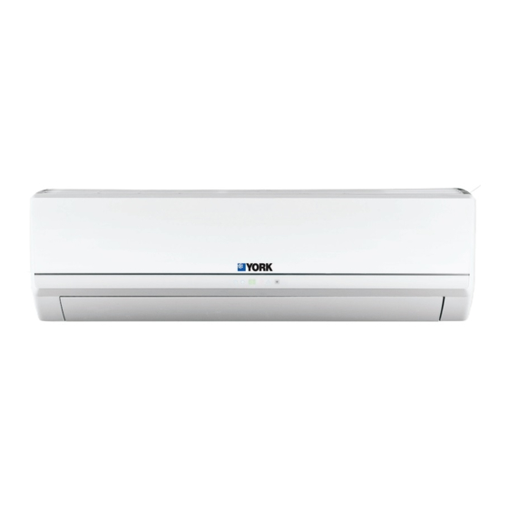
Page 6: Name Of Parts
Name of Parts Indoor unit Air in ⑶ ⑴ ⑸ ⑺ ⑷ ⑹ Air out The icons displayed: :Cool ⑵ :Dry ⑴ Power cord :Heat Power ⑵ : Remote controller :Set temp. ⑶ Front panel ⑷ Filter ⑸ Horizontal louver Outdoor unit Wall pipe ⑹... -
Page 7: Operation Of Wireless Remote Controller
Operation of wireless remote controller Name and function of wireless remote controller Note: Besure that there are no obstructions between receiver and remote controoler; Don't drop or throw the remote control; Don't let any liquid in the remote control and put the remote control directly under the sunlight or any place where is very hot. - Page 8 Operation of wireless remote controller Name and function of wireless remote controller Note: Besure that there are no obstructions between receiver and remote controoler; Don't drop or throw the remote control; Don't let any liquid in the remote control and put the remote control directly under the sunlight or any place where is very hot.
-
Page 9: Remote Controller
Operation of wireless remote controller Name and function of wireless remote controller This wireless remote control is universal, and it could be used for many units, some buttons of this control which are not available to this unit will not be described below. TIMER ON TIMER ON BUTTON Timer On sett ing : Sign al “ON”... - Page 10 Operation of wireless remote controller Name and function of wireless remote controller Press this button, can select Sleep 1 ( ), Sleep 2 ( ● Sleep 3 ( ) and cancel the Sleep, circulate between these, after electrified, Sleep Cancel is defaulted. Sleep 1 is Sleep mode 1, in Cool, Dehumidify modes: sleep status ●...
- Page 11 Operation of wireless remote controller Name and function of wireless remote controller (3) Under the initial presetting temperature 21℃~27℃, after Sleep function started up, the temperature will decrease 1℃ in every hour, after 2 ℃ decreased, this temperature will be maintained. (4) Under the initial presetting temperature 28℃~30℃, after Sleep function started up, the temperature will decrease 1℃...
- Page 12 Operation of wireless remote controller Guide for operation- general operation 1. After powered on, press ON/OFF button, the unit will start to run. (Note: When it is powered on, the guide louver of main unit will close automatically.) 2. Press MODE button, select desired running mode. 3.
- Page 13 Operation of wireless remote controller ★ About lock Press buttons simultaneously to lock or unlock the keyboard. If the remote controller is locked, the icon will be displayed on it, in which case, press any button, the mark will flicker for three times. If the keyboard is unlocked, the mark will disappear. ★...
-
Page 14: Changing Batteries And Notices
Operation of wireless remote controller Changing batteries and notices 1.Slightly to press the place with , along the arrowhead direction to push the back cover of wireless remote controller. (As show in Fig 1. ) 2.Take out the old batteries. 3.Insert two new AAA1.5V dry batteries, and pay attention to the polarity. -
Page 15: Emergency Operation
Emergency Operation Emergency Operation When the remote controller is lost or damaged, please use the manual switch on the main unit. In that case, the unit will operate in AUTO mode and the temperature setting or fan speed can not be changed. The manual switch can be operated as below: Manual switch Turn on the unit: Press AUTO/STOP button to... -
Page 16: Care And Cleaning
Care and Cleaning Caution ● Disconnect the power supply before cleaning and maintenance. ● Do not splash water on the units for cleaning, as electric shocks may occur. ● Wipe the units with a dry soft cloth, or a cloth slightly moistened with water or cleaner (not with volatile liquid such as thinner or gasoline). -
Page 17: Care And Cleaning
Care and Cleaning Check before Use ① Be sure that nothing obstructs the air outlet and inlet. ② Check if the batteries of remote controller are replaced. Check if the installation stand of the outdoor unit is damaged. ③ If damaged, consult the technicians. Maintenance after Use ①... -
Page 18: Troubleshooting
Troubleshooting CAUTION The air conditioner is not user serviceable.Incorrect repair may cause electric shock or fire so please contact an authorized service center for professional repair. Following checks prior to contact may save your time and money. Phenomenon Troubleshooting The unit does not operate: The unit does not operate if it is turned on ●... - Page 19 Troubleshooting Phenomenon Troubleshooting Is the power cut off? ● The unit can not be started up: Is the power plug loose? ( if applicable ) ● Is the circuit protection device tripped off? ● Is voltage higher or lower? ● (Tested by professionals) Breaking off Is the TIMER correctly used?
- Page 20 Troubleshooting Phenomenon Troubleshooting Indoor unit can not blow air: In HEAT mode, when the temperature of indoor ● heat exchanger is very low, air flow is stopped in order to prevent cold air. (Within 2 minutes) In HEAT mode, when the outdoor temperature ●...
-
Page 21: Operation Tips
Operation Tips Cooling Operation Principle: Air conditioners absorb heat in the room and transmit it to the outdoor unit, so that the room temperature is decreased. The cooling capacity will increase or decrease according to outdoor ambient temperature. Antifreezing Function: If the unit is operating in COOL mode and in low ambient temperature, frost may be formed on the heat exchanger. -
Page 22: Operation Tips
Operation Tips Operating Temperature Range Indoor side DB/WB( Outdoor side DB/WB( 32/23 48/—— Maximum cooling 24/18 Maximum heating 27/--- The operating temperature range (outdoor temperature) for cooling only unit is 10℃~ 48℃; for heat pump unit is -20℃ ~48℃. Operating Temperature Range(Optional) Indoor side DB/WB( Outdoor side DB/WB( Maximum cooling... -
Page 23: Notices For Installation
Notices for Installation Caution The unit must only be installed by authorized service center according to local or government regulations and in compliance with this manual. Before installation, please contact with local authorized maintenance center. If the unit is not installed by the authorized service center, the malfunction may not be solved due to discommodious contacts. - Page 24 Notices for Installation Installation Site of Indoor Unit The air inlet and outlet should be away from the obstructions. Ensure the air can be blown through the whole room. Select a site where the condensing water can be easily drained out, and where it is easily connected for outdoor unit.
- Page 25 Notices for Installation Air-conditioner (Btu) Air switch capacity 09 12K 18 24K Note: Make sure the live wire, neutral wire and earth wire in the family power socket are properly ● connected. There should be reliable circuit in the diagram. Inadequate or incorrect electrical connections may cause electric shock or fire.
-
Page 26: Installation Drawing
Installation Drawing Installation Drawing Space to the ceiling 15cm Above Space to the wall 15cm Above 15cm Above Space to the wall 300cm Above Above Air outlet side Space to the floor The dimensions of the space necessary for proper ●... -
Page 27: Installation Of Indoor Unit
Installation of Indoor Unit Installation of Mounting Plate 1. Mounting plate should be installed horizontally. As the water tray's outlet for the indoor unit is two-way type, during installation, the indoor unit should slightly slant to water tray's outlet for smooth drainage of condenser water. -
Page 28: Installation Of Indoor Unit
Installation of Indoor Unit Connecting Indoor and Outdoor Electric Wires 1. Open the front panel. 2. Remove the wiring cover connect and fix power connection cord to the terminal board as shown in Fig 6. 3. Make the power connection cord pass through the hole at the back of indoor unit. 4. -
Page 29: Installation Of Connection Pipe
Installation of Indoor Unit Installation of Indoor Unit External connection Gas side pipe electric wire The piping can be output from right, right rear, left ● Liquid side piping or left rear. When routing the piping and wiring from the left Tailing 2 Gas side piping Tailing 1... -
Page 30: Installation Of Outdoor Unit
Installation of Outdoor Unit Electric Wiring Remove the handle on the right side plate of outdoor unit. Take off wire cord anchorage. Connect and fix power connection cord to the terminal board.Wiring should fit that of indoor unit. Handle Fix the power connection cord with wire clamps and then connect the corresponding connector. -
Page 31: Check After Installation And Operation Test
Check after Installation and Operation Test Check after Installation Items to be checked Possible malfunction Has the unit been fixed firmly? The unit may drop, shake or emit noise. It may cause insuf ficient cooling (heating) Have you done the refrigerant leakage test? It may cause condensation. -
Page 32: Installation And Maintenance Of Healthy Filter
Installation and Maintenance of Healthy Filter Installation of Healthy Filter Lift up the front panel from the two ends of it, as shown by the arrow direction, and (as shown in Fig.a) then remove the air filter. Fig. a Fig. b Attach the healthy filter onto the air filter, Air filter (as shown in Fig.b). -
Page 33: Configuration Of Connection Pipe And Additional Volume Of Refrigerant
Configuration of connection pipe and additional volume of refrigerant 1. Standard length of connection pipe 5m 7.5m 8m 2. Min length of connection pipe For the unit with standard connection pipe of 5m, there is no limitation for the min length of connection pipe. For the unit with standard connection pipe of 7.5m and 8m, the min length of connection pipe is 3m. - Page 34 Configuration of connection pipe and additional volume of refrigerant Sheet 2. Additional refrigerant charging amount for R22 R407C R410A and R134a Diameter of connection pipe mm Indoor unit throttle Outdoor unit throttle Liquid pipe Gas pipe Cooling only, Cooling only Cooling and cooling and heating (g / m)
- Page 35 www.johnsoncontrols.com 2012 Johnson Controls, Inc. Doc. No.:UYHJZHAMQ-120305...
Need help?
Do you have a question about the YWHJZH0012BAMKAFX and is the answer not in the manual?
Questions and answers