
Subscribe to Our Youtube Channel
Related Manuals for York YUKC 07-18


Summary of Contents for York YUKC 07-18
- Page 1 Installation & Owner’s Manual MINISPLIT MODELS YUHC 18-60 AIR BLOWER YUKC 07-18 EN 035M00065-000 J368-EN.indd 1 2/1/07 9:40:52 AM...
-
Page 2: Table Of Contents
CONTENTS Safety Precautions ...........3 Part Names ..............4 Technical Specifications ..........5 Outdoor Unit Dimensions ........9 Preparation Before Installation ......10 Installation ...............10 Condensate Drainage ..........14 Refrigerant Piping Connects ......... 15 Fan Speeds .............16 Wiring Diagrams .............17 Defrosting Operation ..........20 Please read this installation Service and Maintenance ........20 manual carefully before starting Operation Tips ............21... -
Page 3: Safety Precautions
REQUIRED TOOLS EXTENDED PARTS 1. Screw driver 9. Manifold gauge 1. Refrigerant Pipe : See Technical Specification 2. Hexagonal wrench 10. Gas leak detector 2. Pipe insulation material (Polyethylene foam 9 mm thick) 3. Torque wrench 11. Vacuum pump 3. Vinyl tape 4. -
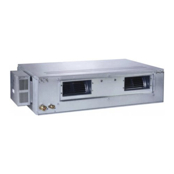
Page 4: Part Names
PART NAMES INDOOR UNIT Display Panel OUTDOOR UNIT ■ INDOOR & OUTDOOR UNIT ■ DISPLAY PANEL A. Indoor unit I. Infrared signal receiver B. Outdoor unit J. Emergency button C. Remote controller K. Running indicator D. Air-in L. Timer indicator E. -
Page 5: Technical Specifications
TECHNICAL SPECIFICATIONS Technical Specifications : Duct Type YUHC “R-410A” -50Hz YUKC Indoor Unit Models YUJC Outdoor Unit V/Ph/Hz 220-240/1/50 380/3/50 Power Supply Power Consumption 1,900/1,900 2,560/2,500 3,250/3,250 3,700/3,350 4,700/4,900 6,000/6,000 Running Current 8.8/8.8 12.2/11 5.5/5.5 6.5/5.8 8.2/8.6 9.8/9.8 Refrigerant Type R-410A Refrigerant Charge 2,050... - Page 6 Technical Specification: Ducted Dc Inverter “YUHC” R-410A, 50Hz. YUHC18DUBAAR-K YUHC24DUBAAR-K YUHC36DUBACR-K YUHC48DUBACR-K YUHC60DSBACR-K Model Indoor YUKC18DU-BAR-K YUKC24DU-BAR-K YUKC36DU-BCR-K YUKC48DU-BCR-K YUKC60DS-BCR-K Outdoor YUJC18DU-BAR YUJC24DU-BAR YUJC36DU-BCR YUJC48DU-BCR YUJC60DS-BCR Power supply V-Ph-Hz 220~240-1-50 220~240-1-50 380V~3~50Hz 380V~3~50Hz 380V~3~50Hz Capacity Btu/h 18,000 24,000 36,000 48,000 60,000 Cooling Input...
- Page 7 TECHNICAL SPECIFICATION: EVEREST MULTI INVERTER “YUKC-RRJC” 50Hz Indoor Unit Duct Type YUKC 07-18 Model YUKC 07AA-AAR YUKC 09AA-AAR YUKC 12AA-AAR YUKC 18AA-AAR Power supply Ph-V-Hz 1Ph, 220-240V~, 50Hz 1Ph, 220-240V~, 50Hz 1Ph, 220-240V~, 50Hz 1Ph, 220-240V~, 50Hz Cooling Capacity BTU/h 7,000 9,000 12,000...
-
Page 8: Operating Temperature
Outdoor Unit Multi Inverter RRJC 18-27 Model RRJC 18AA-AAA RRJC 27AA-AAA Indoor Units Combination Single Double Single Double Treble Power supply Ph-V-Hz 1Ph, 220-240V~, 50Hz 1Ph, 220-240V~, 50Hz Btu/h 7,000~12,000 18,000 7,000~12,000 16,000~24,000 27,000 Capacity 2,050~3,517 5,275 2,000~3,500 4,690~7,000 7,913 Cooling Input 1,000~1,300... -
Page 9: Outdoor Unit Dimensions
OUTDOOR UNIT DIMENSIONS YUJC 18 YUJC 24 301.5 141.5 560.1 YUJC 30-36 YUJC 48-60 336.4 181.4 RRJC 18-27 ENGLISH J368-EN.indd 9 2/1/07 9:40:59 AM... -
Page 10: Preparation Before Installation
DC Inverter R-410A MODEL REMARK R-410A 1,245 PREPARATION BEFORE INSTALLATION • Before doing any work, check the interior power supply cord and the main breaker capacity are sufficient and the installation area is sufficient and complies with the requirements. • Check that the power supply available agrees with name plate voltage. •... - Page 11 YUKC 18-48 The positioning of ceiling hole and indoor unit and hanging screw bolt: Air outlet Hanging Screw bolt N-Ø200 Main body : A 4-M10 Site configuration Distance between bolts: B J=MxK Ceiling hole: D Panel: E Install the main body: Main body: 800 Connecting point of refrigerant pipe...
- Page 12 YUKC 60 The positioning of ceiling hole and indoor unit and hanging screw bolt: Air outlet Hanging Screw bolt N-Ø200 Main body : A 4-M10 Site configuration Distance between bolts: B J=MxK Ceiling hole: D Panel: E Install the main body: Main body: 800 Distance between bolts: 565 Fixed screw...
-
Page 13: Outdoor Units
OUTDOOR UNITS CAUTIONS • Keep this unit away from direct radiation of the sun or other heaters. • If unavoidable, please cover it with a shelter. • In places near coast or with a high attitude where the wind is violent, please install the outdoor unit against the wall to ensure normal performance. -
Page 14: Condensate Drainage
MOVING AND INSTALLING • Since the gravity center of this unit is not at its physical center, so please be careful when lifting it with a sling. • Never hold the air-in of the outdoor unit to prevent it from deforming. Do not touch the fan with hands or other objects. -
Page 15: Refrigerant Piping Connects
REFRIGERANT PIPING CONNECTIONS ■ Fixing and Piping • Piping must be performed by qualified personnel Low pressure High pressure according to good refrigeration system practices. • Piping materials and insulation materials must be of Manifold refrigerant quality. • Select the pipe diameters according to the size of unit and cut the pipe to design length by using pipe cutter. -
Page 16: Fan Speeds
FAN SPEEDS For ducted installations, check air flow and static pressure Insufficient air flow can cause operating problems such against values shown in the following diagrams. as icing which may damage the compressor in the outdoor unit. High speed High speed Low speed Low speed 7 0 0... -
Page 17: Wiring Diagrams
WIRING DIAGRAMS ■ Wiring Prepare the power source for exclusive with the air conditioner. The supply voltage must comply with the rated voltage of the air conditioner. The plug socket shall be accessible after installation. Remark: All the wiring must be based on the wiring nameplate which is shown on the model. CAUTIONS •... - Page 18 YUKC 07 YUKC 09 YUKC 12 YUKC 18 RRJC 18 RRJC 27 A/F IPM(PFC) ENGLISH J368-EN.indd 18 2/1/07 9:41:26 AM...
- Page 19 DC Inverter R-410A INDOOR UNIT Y (E) Power supply 1-Phase 220-240V (3-core cable 3x1.0mm ) 3-core sheild cable Power supply 1-Phase 220-240V (3-core cable 3x2.5mm ) For 18,000-24,000 Btu/h OUTDOOR UNIT 3-core sheild cable Power supply 3-Phase 380-415V (5-core cable 5x2.5mm ) Power supply 1-Phase 220-240V...
-
Page 20: Defrosting Operation
DEFROSTING OPERATION (Available for heating only) 1. Condition to start defrosting: Units will switch to defrosting b. Unit has been running at high temperature protection mode when either of the following conditions is met. mode* for 90 minutes. (*High temperature protection mode: when coil temperature of indoor a. -
Page 21: Operation Tips
OPERATION TIPS The following events may occur during normal operation. 1. Protection of the air conditioner. Compressor protection • The compressor can not restart for 3 minutes after it stops. Anti-cold air (Cooling and heating models only) • The unit is designed not to blow cold air on HEAT mode, when the indoor heat exchanger is in one of the following three situations and the set temperature has not been reached. -
Page 22: Trouble Shooting Guide
TROUBLE SHOOTING GUIDE Problem Probable cause Remedy A. The air conditioner does not 1. Power failure. 1. Wait for power resume. run. 2. Fuse blown or circuit breaker 2. Replace the fuse or reset the open. breaker. 3. Voltage is too low. 3. -
Page 23: Declaration Of Conformity
Authorized Representative: CM Choi Shipping Manager YORK International (Northern Asia) Ltd. 15/F., Tower II, World Trade Square, 123 Hoi Bun Road, Kwun Tong, Kowloon, Hong Kong Telephone: (852) 2331 9286 Fax: (852) 2331 9840 Technical Service Division: Telephone: (852) 2331 9286 Fax: (852) 2304 0068...
Need help?
Do you have a question about the YUKC 07-18 and is the answer not in the manual?
Questions and answers