Table of Contents
Advertisement
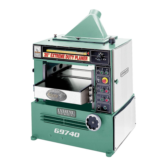
EXTREME-DUTY PLANERS
MODELS G9740/G9740Z/G9741/G9961/G9967/G9967Z
INSTRUCTION MANUAL
Model G9740 Shown
COPYRIGHT © SEPTEMBER, 2003 BY GRIZZLY INDUSTRIAL, INC. REVISED NOVERMBER, 2003.
WARNING: NO PORTION OF THIS MANUAL MAY BE REPRODUCED IN ANY SHAPE
OR FORM WITHOUT THE WRITTEN APPROVAL OF GRIZZLY INDUSTRIAL, INC.
#3978 PRINTED IN TAIWAN
Advertisement
Table of Contents

Subscribe to Our Youtube Channel
Related Manuals for Grizzly G9740


Summary of Contents for Grizzly G9740
- Page 1 MODELS G9740/G9740Z/G9741/G9961/G9967/G9967Z INSTRUCTION MANUAL Model G9740 Shown COPYRIGHT © SEPTEMBER, 2003 BY GRIZZLY INDUSTRIAL, INC. REVISED NOVERMBER, 2003. WARNING: NO PORTION OF THIS MANUAL MAY BE REPRODUCED IN ANY SHAPE OR FORM WITHOUT THE WRITTEN APPROVAL OF GRIZZLY INDUSTRIAL, INC.
- Page 2 Some dust created by power sanding, sawing, grind- ing, drilling, and other construction activities contains chemicals known to the State of California to cause cancer, birth defects or other reproductive harm. Some examples of these chemicals are: • Lead from lead-based paints. •...
-
Page 3: Table Of Contents
G9740/G9740Z Machine Data Sheet ... 33 G9967/G9967Z Machine Data Sheet ... 34 G9741/G9961 Machine Data Sheet ... 35 G9740/G9740Z/G9967/G9967Z Parts Diagrams and List ... 36 G9967/G9967Z Wiring Diagrams ... 61 G9740/G9740Z Wiring Diagrams ... 64 G9741/G9961 Wiring Diagrams ... 67... -
Page 4: Section 1: Safety
SECTION 1: SAFETY For Your Own Safety Read Instruction Manual Before Operating This Equipment The purpose of safety symbols is to attract your attention to possible hazardous conditions. This manual uses a series of symbols and signal words which are intended to convey the level of importance of the safety messages. - Page 5 Safety Instructions For Power Tools 9. USE PROPER EXTENSION CORD. Make sure your extension cord is in good condi- tion. Conductor size should be in accor- dance with the chart below. The amperage rating should be listed on the motor or tool nameplate.
-
Page 6: Additional Safety Instructions For Planers
10. DO NOT REMOVE MORE THAN 11. INSPECT YOUR STOCK BEFORE PLAN- 12. DO NOT ATTEMPT TO REMOVE JAMS 13. DO NOT PLANE WORKPIECES LESS 14. DO NOT OPERATE PLANER WITH DULL 15. ALWAYS ADEQUATE 16. IF AT ANY TIME YOU ARE EXPERIENC- No list of safety guidelines can be complete. -
Page 7: Section 2: General Information
However, owing to Grizzly’s policy of continuous improvement, changes may be made at any time with no obligation on the part of Grizzly. For your convenience, we always keep current Grizzly manuals available on our website at www.griz- zly.com. -
Page 8: Section 3: Circuit Requirements
Figure 1. Typical 6-50 plug and receptacle. G9740/G9740Z The Model G9740/G9740Z is prewired with a 7 HP 220V 3-phase motor, which may be rewired to 440V. Please use the following specs preparing your shop for the machine, and always have the wiring inspected by licensed electrician before operating your machine. -
Page 9: G9741/G9961
G9741/G9961 The Model G9740/G9740Z Planer is prewired with a 10 HP 3-phase motor, which may be rewired to 440V. Please use the following specs preparing your shop for the machine, and always have the wiring inspected by licensed electrician before operating your machine. -
Page 10: Rewire To 440V
Rewire to 440V The Model G9740/G9740Z/G9741/G9961 can be rewired from 220V to 440V. Before rewir- ing, purchase the Grizzly 440V conversion kit (#P97400120-11). Please Note—The Model G9967/G9967Z cannot be rewired to 440V. The 440V wiring conversion procedure requires rewiring the transformer, installing new overload... -
Page 11: Section 4: Machine Features
SECTION 4: MACHINE FEATURES About this Section Familiarize yourself with the planer controls before turning the machine on. Figures 18 and 19 point out these controls. Table Height Cutterhead Motor Power Indicator Light Figure 18. Control panel. Cutterhead Lock Table Roller Height Control Figure 19. -
Page 12: Section 5: Set Up
SECTION 5: SET UP About this Section The purpose of this section is to guide you through the required steps to get your machine out of its crate and into operating condition. This machine presents serious injury hazards to untrained users. Read through this entire man- ual to become familiar with the controls and... -
Page 13: Piece Inventory
Piece Inventory After all the parts have been removed from the carton, you should have: G9740/G9741/G9967 (4-Knife Cutterheads) Part • Planer Unit • Dust Hood • Combo Wrench 11x13 • Combo Wrench 12x14 • Combo Wrench 17x19 • Hex Wrench 5mm •... -
Page 14: Hardware Recognition Chart
Hardware Recognition Chart -12- Extreme Duty Planers... -
Page 15: Clean Up
Remove this protective coating with a sol- vent cleaner or citrus-based degreaser such as Grizzly’s G7895 Degreaser. To clean thoroughly, some parts may need to be removed. For opti- mum performance from your machine, make sure you clean all moving parts or sliding contact surfaces that are coated. -
Page 16: Section 6: Assembly
SECTION 6: ASSEMBLY Beginning Assembly Most of your Extreme Duty Planer has been assembled at the factory, but some parts must be assembled or installed after delivery. We have organized the assembly process into steps. Please follow along in the order presented in this section. -
Page 17: Table Rollers
Table Rollers The height of the table rollers will vary, depending on the type of material you intend to plane. When planing rough stock, you will need to set the roll- ers high to keep the lumber from dragging along the table. -
Page 18: Test Run
Run the planer for a short time to ensure that the moving parts are working properly with no exces- sive vibration. If any problem develops, correct it before attempting to use the machine. -
Page 19: Section 7: Operations
• Use the full width of the planer, Alternate between the left, the right and the middle when feeding lumber into the planer. Your knives will remain sharp much longer. -
Page 20: Wood Characteristics
Chatter marks can also be caused by running a narrow wood piece through the planer at either the right or left end of the cutterhead. Chatter, like uneven knife marks, will show in the form of a “washboard”... -
Page 21: Section 8: Maintenance
General Periodic maintenance on your 20" Extreme Duty Planer Planer ensures its optimum performance. Make a habit of inspecting your planer each time you use it. Check for the following conditions and repair or replace when necessary. -
Page 22: V-Belt
Transmission Box — Lubricate after every 12 hours of continuous use. See Figure 21 for location. Figure 21. Transmission box grease fitting. Table Lifting Gears — Once a week for heavy use; once a month for moderate use. See Figure 22 for locations. Figure 22. -
Page 23: Maintenance Log
Maintenance Log Maintenance Performed Date Approximate Hours Of Use Extreme Duty Planers -21-... -
Page 24: Section 9: Service Adjustments
This section is provided for your convenience— it is not a substitute for the Grizzly Service Department. If any adjustments arise that are not described in this manual, then feel free to call the Grizzly Service Department at (570) 546-9663. -
Page 25: Cutterhead Knives
Cutterhead Knives The Model G9740/G9741/G9967 features a 4- knife cutterhead. The knives are factory set to .071". Unless you are having problems related to the knives or are removing them for sharpen- ing/replacement, assume that your knives are adjusted correctly. To be safe, always test the planer with a scrap piece of wood before using expensive stock. -
Page 26: Carbide Cutters
Planer Pal available in the current ® Grizzly catalog. Using magnets, a pair of these devices will automatically hold the knife blades within .001" of each other, thereby allowing you to quickly and accurately lock the knife in place. - Page 27 Figure 10. Always rotate carbide cutters in the same direction to keep track of the dull or damaged edges. To install/adjust the carbide cutters: Disconnect the planer from the power source! Open the top cover door to gain access to the cutterhead, and open the left-hand service door to gain access to the cutterhead pulley, so you can safely rotate the cutterhead.
-
Page 28: Table
Rotacator ing adjustments to your planer. This tool is well worth the money, because it provides accuracy within .001". Check with the current Grizzly cata- log for details. As an alternative to using a Rotacator a block of scrap wood to aid in checking the table. - Page 29 Make sure the planer is disconnected from the power source! Models G9740Z and G9967Z skip this step. For Models G9740 and G9967, open the left side service door. Locate the cutterhead lock shown in Figure 11. Pull up and twist so the end of the lock will drop.
- Page 30 To adjust the table with the wood block: Make sure the planer is disconnected from the power source! Place the wood block on the side of the table where the tightest gap exists between the table and the cutterhead.
-
Page 31: Feed Rollers & Pressure Bar
Although not required, we recommend using a Rotacator for the following setup. Check with the ® current Grizzly catalog for details. To set the feed rollers and pressure bar with hardwood blocks: Make sure the machine is disconnected from power and the knives have been... - Page 32 Working from the back of the planer is easi- est because the anti-kickback pawls hang down in the front. Place a piece of newspa- per on each wood block so it is both under the cutterhead and accessible from the back of the planer.
-
Page 33: Feed Roller Tension
To adjust the pressure on the chip breaker segments: Make sure the planer is disconnected from the power source! Rotate the knurled adjustment rings shown in Figure 18 either left or right to increase or decrease the spring tension. -
Page 34: Section 10: Closure
However, due to Grizzly’s policy of continuous improvement, changes may be made at any time with no obligation on the part of Grizzly. Whenever possible, though, we send manual updates to all owners of a particular tool or machine. Should you receive one, add the new information to this manual and keep it for reference. -
Page 35: G9740/G9740Z Machine Data Sheet
Cuts Per Inch ...41.6 - 83.3 Construction: Table ... Precision-Ground Cast Iron Power Feed Rollers ...Steel, Segmented Infeed, Polished Outfeed Cutterhead (G9740) ...4 Knife, High Speed Steel, 20" x 1 Cutterhead (G9740Z) ... Spiral w/Indexable Carbide Inserts Motors: Cutterhead Motor ... 7 Amps ... -
Page 36: G9967/G9967Z Machine Data Sheet
Customer Service #: (570) 546-9663 • To Order Call: (800) 523-4777 • Fax #: (800) 438-5901 20" EXTREME DUTY PLANER Design Type ... Floor Model Overall Dimensions: Table Size ...24" x 35 Overall Depth ...36" Overall Width ... 42 Shipping Weight ... 1807 lbs Net Weight ... -
Page 37: G9741/G9961 Machine Data Sheet
Customer Service #: (570) 546-9663 • To Order Call: (800) 523-4777 • Fax #: (800) 438-5901 24" EXTREME DUTY PLANER Design Type ... Floor Model Overall Dimensions: Table Size ...28" x 35 Overall Depth ...36" Overall Width ... 46 Shipping Weight ... 1943 lbs Net Weight ... -
Page 38: G9740/G9740Z/G9967/G9967Z Parts Diagrams And List
G9740/G9740Z/G9967/G9967Z/G9741/G9961 -36- Extreme Duty Planers... - Page 39 G9740/G9740Z/G9967/G9967Z/G9741/G9961 Extreme Duty Planers -37-...
- Page 40 G9740/G9740Z/G9967/G9967Z/G9741/G9961 PART # DESCRIPTION P97400101 CABINET (20") P97410101 CABINET (24") P97400102 SPEED CHANGE NUT P97400103 HANDWHEEL P97400104 SLIP BOLT PW06 FLAT WASHER 1⁄4 PSB62 CAP SCREW 1⁄4-20 X 1 1⁄2 PLW04M LOCK WASHER 8MM PB07M HEX BOLT M8-1.25 X 25 P97400109 MOTOR MOUNT (20")
- Page 41 G9740/G9740Z/G9967/G9967Z/G9741/G9961 Extreme Duty Planers -39-...
- Page 42 G9740/G9740Z/G9967/G9967Z/G9741/G9961 PART # DESCRIPTION P97400301 RIGHT WALL PN09M HEX NUT M12-1.75 PN04 HEX NUT 5⁄8-11 P97400304 SPROCKET SHAFT P97400305 SPROCKET P6201 BALL BEARING 6201 PR29M INT RETAINING RING 32MM P97400308 SPECIAL WASHER 8MM PSB52M CAP SCREW M8-1.25 X 10 P97400310...
- Page 43 G9740/G9740Z/G9967/G9967Z/G9741/G9961 Extreme Duty Planers -41-...
- Page 44 G9740/G9740Z/G9967/G9967Z/G9741/G9961 PART # DESCRIPTION P97400401 TABLE (20") P97410401 TABLE (24") P97400402 TABLE ROLLER (20") P97410402 TABLE ROLLER (24") P97400403 ECCENTRIC SHAFT (20") P97410403 ECCENTRIC SHAFT (24") P6006 BALL BEARING 6006 P97400405 ECCENTRIC PULL ROD P97400406 SHORT ROLLER ADJ BAR P97400407...
- Page 45 G9740/G9740Z/G9967/G9967Z/G9741/G9961 Extreme Duty Planers -43-...
- Page 46 G9740/G9740Z/G9967/G9967Z/G9741/G9961 -44- Extreme Duty Planers...
- Page 47 G9740/G9740Z/G9967/G9967Z/G9741/G9961 Extreme Duty Planers -45-...
- Page 48 G9740/G9740Z/G9967/G9967Z/G9741/G9961 PART # DESCRIPTION P97400501 OUTFEED ROLLER (20") P97410501 OUTFEED ROLLER (24") P97400502 LEFT BEARING BLOCK (RT) P97400503 FIXED BEARING NUT P97400504 LEFT CASE COVER P6205 BALL BEARING 6205 P97400506 RIGHT BEARING BLOCK (LT) P97400507 RIGHT CASE COVER P97400508 SPROCKET WASHER...
- Page 49 G9740/G9740Z/G9967/G9967Z/G9741/G9961 Extreme Duty Planers -47-...
- Page 50 G9740/G9740Z/G9967/G9967Z/G9741/G9961 -48- Extreme Duty Planers...
- Page 51 G9740/G9740Z/G9967/G9967Z/G9741/G9961 1001 1011 1012 Extreme Duty Planers 1010 1009 1008 1007 1006 1005 1003 1004 1002 1004 -49-...
- Page 52 G9740/G9740Z/G9967/G9967Z/G9741/G9961 PART # DESCRIPTION P97400801 LEFT WALL THIN SHORT P97400802 RIGHT WALL THICK SHORT P97400803 SWITCH PLATE PS65M PHLP HD SCR M6-1 X 10 P97400805 PUSH-BUTTON SWITCH T1 P97400806 SWITCH RED P97400807 PUSH-BUTTON SWITCH T2 P97400808 ELEVATION LOCK STUD P97400809...
- Page 53 G9740/G9740Z/G9967/G9967Z/G9741/G9961 1113 1113 1108 1104 1103 1106 1101 1107 1101-2 1101-1 1101-3 1111 1101-5 1110 1109 1101-4 1105 1112 1102 Extreme Duty Planers -51-...
- Page 54 G9740/G9740Z/G9967/G9967Z/G9741/G9961 1207 1204 1205 1204 1201-2 1201-1 1202 1201-3 1201-5 1206 1201-4 1210 1201 1208 1203 1209 -52- Extreme Duty Planers...
- Page 55 P99671101 G9967/Z MOTOR 5HP, 1Ø 1101 P97411101 G9741/61 MOTOR 10HP, 3Ø 1101-1 P97401101-1 G9740/Z MOTOR COVER 1101-1 P99671101-1 G9967/Z MOTOR COVER 1101-1 P97411101-1 G9741/61 MOTOR COVER 1101-2 P97401101-2 G9740/Z MOTOR FAN 1101-2 P99671101-2 G9967/Z MOTOR FAN 1101-2 P97411101-2 G9741/61 MOTOR FAN...
- Page 56 G9740/G9740Z/G9967/G9967Z/G9741/G9961 -54- Extreme Duty Planers...
- Page 57 G9740/G9740Z/G9967/G9967Z/G9741/G9961 Extreme Duty Planers -55-...
- Page 58 G9740/G9740Z/G9967/G9967Z/G9741/G9961 1301 P97401301 TRANSMISSION BOX 1302 P97401302 TRANSMISSION BOX GEAR 1303 P97401303 TRANSMISSION BOX CAP 1304 P97401304 TRANSMISSION SHAFT 1305 P97401305 GEAR SHAFT 1306 P97401306 BEARING SPACER 1307 P6204 BALL BEARING 6204 1308 P97401308 TRANSMISSION SPROCKET 1309 P97401309 TRANNY PULLEY 8” (3Ø)
- Page 59 G9740/G9740Z/G9967/G9967Z/G9741/G9961 1502 1507 1509 1508 1507 1508 1510 1510 1506 1505 1505 1511 1506 1512 1503 1504 Extreme Duty Planers -57-...
- Page 60 G9740/G9967/G9741 4-Knife Cutterhead -58- Extreme Duty Planers...
- Page 61 G9740Z/G9967Z/G9961 Spiral Cutterhead Extreme Duty Planers -59-...
- Page 62 G9740/G9740Z/G9967/G9967Z/G9741/G9961 PART # DESCRIPTION 1501 P97401501 DISCHARGE COVER (20") 1501 P97411501 DISCHARGE COVER (24") 1502 P97401502 DUST PORT (20") 1502 P97411502 DUST PORT (24") 1503 P97401503 RUBBER SEAL (20") 1503 P97411503 RUBBER SEAL (24") 1504 PS26M PHLP HD SCR M6-1 X 20 1505 PW06 FLAT WASHER 1⁄4...
-
Page 63: G9967/G9967Z Wiring Diagrams
220V 220V 800uf 250V 30uf 350V Extreme Duty Planers 220 Volt Single Phase TABLE MOTOR FEED ROLLER MOTOR MOTOR LEADS CUTTER HEAD MOTOR Motors Voltage Diagram Disconnect machine from power before performing any electrical service. Failure to do this will result in a shock hazard leading to injury or death. - Page 64 -62- 10 12 13 14 20 M3 M3 M3 M2 M2 TABLE LIMIT SWITCH M2 M1 M1 Switch Plate Diagram 220 Volt Single Phase Disconnect machine from power before performing any electrical service. Failure to do this will result in a shock hazard leading to injury or death.
- Page 65 Transformer 3 Amp Fuses POWER SWITCH PANEL Extreme Duty Planers Main Hook Up Panel 220 Volt Single Phase U3 V3 W3 9 RHN -18 set relay at full load motor current FN 0820 test man auto 10 12 13 14 20 M3 M3 M3 M2 M2 M2 TABLE LIMIT SWITCHES Disconnect power from machine...
-
Page 66: G9740/G9740Z Wiring Diagrams
220V 220V 220V -64- Voltage Conversion 220 Volt 3-Phase 440V 440V 440V Disconnect power from machine before performing any electrical service. Failure to do this will result in a shock hazard leading to injury or death. Motors TABLE MOTOR FEED ROLLER MOTOR CUTTER... - Page 67 Extreme Duty Planers 10 12 13 14 20 M3 M3 M3 M2 M2 TABLE LIMIT SWITCH M2 M1 M1 Switch Plate Diagram 220 Volt 3-Phase Disconnect machine from power before performing any electrical service. Failure to do this will result in a shock hazard leading to injury or death.
- Page 68 Transformer 3 Amp Fuses POWER -66- RHN -18 set relay at full load motor current FN 0820 test man auto 10 12 13 14 20 U3 V3 W3 U2 V2 W2 U1 V1 W1 SWITCH PANEL TABLE LIMIT SWITCHES Disconnect machine from power performing any electrical service.
-
Page 69: G9741/G9961 Wiring Diagrams
G9741/G9961 Motors Voltage Conversion 220V to 440V, 3-Phase Extreme Duty Planers -67-... - Page 70 G9741/G9961 -68- Extreme Duty Planers...
- Page 71 Transformer 3 Amp Fuses POWER SWITCH PANEL Extreme Duty Planers RHN -18 set relay at full load motor current FN 0820 test man auto 10 12 13 14 20 U3 V3 W3 U2 V2 W2 TABLE LIMIT SWITCHES Disconnect machine from power before performing any electrical service.
-
Page 72: Warranty And Returns
Warranty and Returns Grizzly Industrial, Inc. warrants every product it sells for a period of 1 year to the original purchaser from the date of purchase. This warranty does not apply to defects due directly or indirectly to misuse, abuse, negligence, accidents, repairs or alterations or lack of maintenance. -
Page 73: Warranty Card
Do you think your purchase represents good value? ___Yes Would you recommend Grizzly Industrial to a friend? ___Yes Would you allow us to use your name as a reference for Grizzly customers in your area? Note: We never use names more than three times. ___Yes Comments:_______________________________________________... - Page 74 FOLD ALONG DOTTED LINE FOLD ALONG DOTTED LINE Send a Grizzly Catalog to a friend: Name_______________________________ Street_______________________________ City______________State______Zip______ GRIZZLY INDUSTRIAL, INC. P.O. BOX 2069 BELLINGHAM, WA 98227-2069 TAPE ALONG EDGES--PLEASE DO NOT STAPLE Place Stamp Here...
- Page 76 Buy Direct and Save with Grizzly Visit Our Website Today And Discover Why • • • – Trusted, Proven and a Great Value! ® Grizzly Is The Industry Leader! ® SECURE ORDERING ORDERS SHIPPED WITHIN 24 HOURS E-MAIL RESPONSE WITHIN ONE HOUR...
Need help?
Do you have a question about the G9740 and is the answer not in the manual?
Questions and answers